Page 41 of 232

The essentials
●
Only u
se wheel bolts which correspond to
the wheel rims in question.
● Never use different wheel bolts.
● The bolts and threads should be clean, free
of oil
and grease and easy to thread.
● To loosen and tighten the wheel bolts, al-
way
s use the wheel brace supplied with the
vehicle.
● Loosen the wheel bolts only about one turn
before r
aising the vehicle with the jack.
● Never grease or lubricate wheel bolts or the
wheel hub thre
ads. Although they have been
tightened to the prescribed torque, they
could come loose while driving.
● Never loosen the bolted joints of wheel
rims with bo
lted ring trims.
● If the wheel bolts are not tightened to the
correct
torque, they may come loose while
driving, and the bolts and rims may come
out. If the tightening torque is too high, the
wheel bolts and threads can be damaged. Raising the vehicle with the jack
Fig. 55
Jack position points. Fig. 56
Jack mounted on the left rear part of
the v
ehic
le The jack may be applied only at the jacking
points
sho
wn (m
arks on chassis) ››› Fig. 55.
Always the relevant jacking point for the
wheel to be changed ››› .
R ai
se the
vehicle using only the designated
jacking points. » 39
Page 42 of 232

The essentials
WARNING
If the vehicle is not correctly raised, it could
fa l
l off the jack causing serious injury. Please
observe the following rules to minimise the
risk of injury:
● You should only use a jack approved by
SEAT f
or your vehicle. Other jacks, even those
approved for other SEAT models, might slip
out of place.
● The ground should be firm and flat. If the
ground i
s sloped or soft then the vehicle
could slip and fall off the jack. If necessary,
support the jack on a wide solid base.
● If the ground is slippery, such as tiles,
plac
e a non-slip surface (a floor mat, for in-
stance) beneath the jack to avoid slipping.
● Only fit the jack at the prescribed jacking
points. The c
law of the jack should grip the
reinforcement nerve on the underbody
››› Fig. 56.
● You should never place a body limb such as
an arm or leg u
nder a raised vehicle that is
solely supported by the jack.
● If you have to work underneath the vehicle,
you mus
t use suitable stands additionally to
support the vehicle, there is a risk of acci-
dent!.
● Never raise the vehicle if it is tilting to one
side or the engine i
s running.
● Never start the engine when the vehicle is
raised.
The vehicle may come loose from the
jack due to the engine vibrations. Removing and fitting a wheel
Fig. 57
Changing a wheel: loosen wheel bolts
w ith the soc
k
et at the end of the wheel brace Change the wheel after loosening the wheel
bo
lts
and r
aising the vehicle with the jack.
Removing the wheel
● Slacken the wheel bolts ›››
page 38.
● Raise the vehicle ›››
page 39.
● Using the hexagonal socket in the wheel
brace ›
›› Fig. 57, unscrew the slackened
wheel bolts and place them on a clean sur-
face.
● Take off the wheel.
How to u
se the spare wheel or temporary
spare wheel
Check the direction of rotation of the tyre
››› page 208, Tyre code. ●
Place the s
pare wheel or temporary spare
wheel into position.
● Replace the wheel bolts and tighten slight
-
ly using the hexagonal socket on the end of
the wheel brace.
● To tighten the anti-theft locking wheel bolts
use the corr
esponding adaptor.
● Lower the car with the jack.
● Tighten all of the wheel bolts clockwise
›››
. Tighten the bolts in diagonal pairs (not
in a c ir
c
le).
● Put the caps, trim or full hubcap back on
›››
page 37. WARNING
If the wheel bolts are not treated suitably or
not tight ened t
o the correct torque then this
could lead to loss of vehicle control and to a
serious accident.
● All the wheel bolts and hub threads should
be cle
an and free of oil and grease. The wheel
bolts should be easily tightened to the cor-
rect torque.
● The hexagonal socket in the wheel brace
should be u
sed for turning wheel bolts only.
Do not use it to loosen or tighten the wheel
bolts. 40
Page 43 of 232

The essentials
Tyres with compulsory direction of ro-
t ation A directional tread pattern can be identified
by
the arr
ows on the sidewall that point in
the direction of rotation. Always observe the
direction of rotation indicated when fitting
the wheel to guarantee optimum properties
of this type of tyres with regard to grip,
noises, wear and aquaplaning.
If it is absolutely necessary to fit the spare
tyre* against the direction of rotation, drive
with care as this means the tyre does not of-
fer optimum driving properties. This is of par-
ticular importance when the road surface is
wet.
To return to directional tread tires, replace
the punctured tyre as soon as possible and
restore the obligatory direction of rotation of
all tyres.
After the wheel change ●
Clean the vehicle tools, if necessary and
p ut
them a
way in the luggage compartment
foam holder ›››
page 70.
● Store the spare wheel, the temporary spare
wheel or the ch
anged wheel securely in the
luggage compartment. ●
Have the tightenin
g torque of the wheel
bolts checked as soon as possible with a tor-
que wrench ››› page 38.
● Have the flat tyre replaced as quickly as
poss
ible.
Snow chains Use When using snow chains, applicable local
l
e
gi
slation and maximum permitted speed
limits must be observed.
In winter weather, snow chains not only help
to improve grip but also improve the braking
capacity.
The fitting of chains is permitted only on
front wheels and with the following combi-
nations of wheel trims and tyres :
Tyre sizeWheel rim
165/70 R145 J x 14 offset of 35175/65 R14 SEAT recommends you ask a technical serv-
ic
e f
or f
urther information on wheel, tyre and
chain sizes.
Wherever possible use fine-link chains meas-
uring less than 15 mm including the lock. Remove wheel hub covers and trim rings be-
fore fittin
g snow chains ››› . The wheel bolts
shou l
d be c
overed with caps for safety rea-
sons. These are available from technical serv-
ices.
Temporary spare wheel
For technical reasons, snow chains must not
be used on the compact temporary spare
wheel ›››
page 207.
If it is necessary to fit chains with the tempo-
rary spare wheel in use, install the wheel on
the rear axle in the event of a fault in a front
wheel. Then, fit the rear wheel that is free, in-
stead of the damaged front wheel. In this sit-
uation, observe the rotating direction of the
wheels. SEAT recommends attaching the
snow chains before fitting the wheel. WARNING
The use of unsuitable or incorrectly fitted
ch ain
s could lead to serious accidents and
damage.
● Always the appropriate snow chains.
● Observe the fitting instructions provided by
the snow c
hain manufacturer.
● Never exceed the maximum permitted
speeds
when driving with snow chains. » 41
Page 44 of 232

The essentials
CAUTION
● Remo v
e the snow chains to drive on roads
without snow. Otherwise they will impair
vehicle handling, damage the tyres and wear
out very quickly.
● Wheel rims may be damaged or scratched if
the chain
s come into direct contact with
them. SEAT recommends the use of covered
snow chains. Note
Snow chains are available in different sizes
acc or
ding to the vehicle type. Emergency towing of the vehi-
c
l
e
T
owing Fig. 58
Right side of the front bumper: tow-
line anc hor
ag
e screwed in. Towline anchorages
Att
ac
h the b
ar or rope to the towline ancho-
rages.
It is located with the vehicle's tools
››› page 70.
Screw the front towline anchorage into the
screw connection ››› Fig. 58 and tighten it
with the wheel brace.
Tow rope or tow bar
When towing, the tow bar is the safest and
vehicle friendly way. You should only use a
tow rope if you do not have a tow bar. A tow rope should be slightly elastic to avoid
damag
e to both vehicles. It is advisable to
use a tow rope made of synthetic fibre or sim-
ilarly elastic material.
● Only secure the tow rope or tow bar to the
towline anc
horage or specially designed fit-
ting.
Notes for the driver of the towed vehicle
● Keep the ignition running to prevent the
steerin
g wheel from locking and also to allow
the use of the turn signals, horn, windscreen
wipers and washers.
● As the power assisted steering does not
work if
the engine is not running, you will
need more strength to steer than normally.
● The brake must be depressed much harder
as the br
ake servo does not operate. Avoid
hitting the towing vehicle.
● Note the instructions and information con-
tained in the Ins
truction Manual for the vehi-
cle to be towed.
Notes for the driver of the towing vehicle
● Accelerate gently and carefully. Avoid sud-
den manoeuvr
es.
● Brake well in advance than usual and brake
gently.
● Not
e the instructions and information con-
tained in the In s
truction Manual for the vehi-
cle to be towed. 42
Page 45 of 232

The essentials
Driving style
T o
w
ing requires some experience, especially
when using a tow rope. Both drivers should
realise how difficult it is to tow a vehicle. In-
experienced drivers should not attempt to
tow.
Do not pull too hard with the towing vehicle
and take care to avoid jerking the tow rope.
When towing on an unpaved road, there is al-
ways a risk of overloading and damaging the
anchorage points.
Switch on the ignition so that the turn sig-
nals, windscreen wipers and windscreen
washer can work. Ensure that the steering
wheel is unlocked and moves freely.
Place the gear lever in neutral on vehicles
with a manual gearbox. With an automatic
gearbox, place the lever in N.
To brake, press the brake pedal firmly. The
brake servo does not work when the engine
is switched off.
The power steering only works when the igni-
tion is switched on and the vehicle is moving,
provided that the battery is sufficiently charg-
ed. Otherwise, it will need more force.
Ensure that the tow rope remains taut at all
times. ››› in Instructions for tow-starting on
page 76
››› page 75 Tow-starting
In general, the vehicle should not be started
by
t
owing. Jump-starting is much more pref-
erable ››› page 43.
For technical reasons, the following vehicles
can not be tow started:
● Vehicles with an automatic gearbox.
● If the vehicle battery is flat, it is possible
that the en
gine control unit does not operate
correctly.
However, if your vehicle must absolutely be
tow-started (manual gearbox):
● Put it into second or third gear.
● Keep the clutch pressed down.
● Switch on the ignition and the hazard warn-
ing lights.
● Rel
ease the clutch when both vehicles are
movin
g.
● As soon as the engine starts, press the
clutc
h and move the gear lever into neutral.
This helps to prevent a collision with the tow-
ing vehicle. How to jump start
Jump lea
ds If the engine fails to start because of a dis-
ch
ar
ged battery, the battery of another vehi-
cle can be used to start the engine. Before
starting, check the magic eye on the battery
››› page 196.
For starting assistance, jump lead cables con-
forming to the standard DIN 72553 are re-
quired (see the cable manufacturer instruc-
tions). The cable section in vehicles with pet-
rol engine must be at least 25 mm 2
. WARNING
Incorrect use of jump leads and incorrectly
jump st ar
ting could cause the battery to ex-
plode resulting in serious injury. Please ob-
serve the following rules to minimise the risk
of a battery explosion:
● The battery providing current must have
the same v
oltage (12V) and approximately
the same capacity (see markings on battery)
as the flat battery.
● Never charge a frozen or recently thawed
batter
y. A flat battery can also freeze at tem-
peratures close to 0°C (+32°F).
● If a battery is frozen and/or has been frozen
then it mus
t be replaced.
● A highly explosive mixture of gases is re-
lea
sed when the battery is being charged. Al-
ways keep lit cigarettes, flames, sparks and » 43
Page 46 of 232

The essentials
fire far from the battery. Never use a mobile
tel
ephone when c
onnecting and removing the
jump leads.
● Charge the battery only in well ventilated
area
s given that when the battery is charged
by outside assistance, it creates a mix of
highly explosive gases.
● Jump leads should never enter into contact
with mov
ing parts in the engine compart-
ment.
● Never switch the positive and negative
pole
s or connect the jump leads incorrectly.
● Note the instruction manual provided by
the manufact
urer of the jump leads. CAUTION
To avoid considerable damage to the vehicle
electric a
l system, note the following careful-
ly:
● If the jump leads are incorrectly connected,
this c
ould result in a short circuit.
● The vehicles must not touch each other,
otherwi
se electricity could flow as soon as
the positive terminals are connected. How to jump start: description
Fig. 59
Diagram of connections for vehicles
w ithout
Start Stop system Fig. 60
Diagram of connections for vehicles
w ith
St
art Stop system Jump lead terminal connections
Swit
c
h off the ignition of both vehicles
››› .
1. Connect one end of the
re
d
jump lead to
the positive + terminal of the vehicle
w ith the fl
at
battery A
› ››
Fig. 59
.
C
onnect the other end of the red jump
lead to the positive terminal + in the
v ehic
l
e providing assistance B .
F or
vehicles without Start-Stop system:
connect one end of the black jump lead
to the negative terminal – of the vehi-
c l
e pr
oviding the current B
› ››
Fig. 59
.
F
or vehicles with Start-Stop system: con-
nect one end of the black jump lead X to a suitable ground terminal, to a solid
piec
e of
met
al in the engine block, or to
the engine block itself ››› Fig. 60.
Connect the other end of the black jump
lead X to a solid metal component bol-
t ed t
o the en
gine block or to the engine
block itself of the vehicle with the flat
battery. Do not connect it to a point near
the battery A .
P o
s
ition the leads in such a way that
they cannot come into contact with any
moving parts in the engine compart-
ment.
Starting Start the engine of the vehicle with the
boosting battery and let it run at idling
speed.
2.
3.
4a.
4b.
5.
6.
7.
44
Page 47 of 232

The essentials
Start the engine of the vehicle with the
fl at
b
attery and wait for 2 or 3 minutes
until the engine is running.
Removing the jump leads Before you remove the jump leads,
switch off the dipped beam headlights if
they are switched on.
Turn on the heater blower and heated
rear window in the vehicle with the flat
battery. This helps minimise voltage
peaks which are generated when the
leads are disconnected.
When the engine is running, disconnect
the leads in reverse order to the details
given above.
Make sure the battery clamps have sufficient
metal-to-metal contact with the battery termi-
nals.
If the engine fails to start after about 10 sec-
onds, switch off the starter and try again after
about 1 minute. WARNING
● Ple a
se note the safety warnings referring to
working in the engine compartment
››› page 187.
● The battery providing assistance must have
the same v
oltage as the flat battery (12V) and
approximately the same capacity (see imprint 8.
9.
10.
11.
on battery). Failure to comply could result in
an exp
lo
sion.
● Never use jump leads when one of the bat-
teries
is frozen. Danger of explosion! Even af-
ter the battery has thawed, battery acid could
leak and cause chemical burns. If a battery
freezes, it should be replaced.
● Keep sparks, flames and lighted cigarettes
awa
y from batteries, danger of explosion.
Failure to comply could result in an explo-
sion.
● Observe the instructions provided by the
manufact
urer of the jump leads.
● Do not connect the negative cable from the
other vehic
le directly to the negative terminal
of the flat battery. The gas emitted from the
battery could be ignited by sparks. Danger of
explosion.
● Never attach the negative cable to fuel sys-
tem component
s or the brake lines in the oth-
er vehicle.
● The non-insulated parts of the battery
clamp
s must not be allowed to touch. The
jump lead attached to the positive battery
terminal must not touch metal parts of the ve-
hicle, this can cause a short circuit.
● Position the leads in such a way that they
cannot c
ome into contact with any moving
parts in the engine compartment.
● Do not lean on the batteries. This could re-
sult
in chemical burns. Note
The vehicles must not touch each other, oth-
erw i
se electricity could flow as soon as the
positive terminals are connected. Changing the wiper blades
Wind s
creen wipers service position Fig. 61
Wipers in service position. The wiper arms can be raised when the wip-
er
s
ar
e in service position ›››
Fig. 61.
● Close the bonnet ›››
page 187.
● Switch the ignition on and off.
● Press the windscreen wiper lever down-
ward
s briefly ›››
Fig. 32 4 .
» 45
Page 48 of 232

The essentials
Before driving, always lower the wiper arms.
When the ignition i s
sw
itched on, the wind-
screen wiper arms return to their initial posi-
tion upon activating the windscreen wiper
lever.
››› page 75 Changing the front wiper blades
Fig. 62
Changing the front wiper blades Fig. 63
Changing the rear wiper blade Lifting and unfolding the wiper arms
The w
iper arm m
a
y only be lifted at the point
where it is fastened to the blade.
The wiper should be in service position be-
fore unfolding it ›››
page 108.
Cleaning windscreen wiper blades ● Lifting and unfolding the wiper arms.
● Use a soft cloth to remove dust and dirt
from the wind
screen wiper blades.
● If the blades are very dirty, a sponge or
damp cloth m
ay be used ››› in Changing
the w ind
s
creen and rear window wiper
blades on page 75.
Changing the windscreen wiper blades
● Lifting and unfolding the wiper arms. ●
Hold do
wn the release button ››› Fig. 62 1 while gently pulling the blade in the direction
of
the arr
o
w.
● Fit a new wiper blade of the same len
gth
and design on to the wiper arm and hook it
into place.
● Rest the wiper arms back onto the wind-
scr
een.
Changing the rear wiper blade
● Lift the windscreen wiper arm and fold it at
an angle of
approximately 60° ››› Fig. 63.
● Press and hold the release button 1 .
● Fold the wiper blade towards the wind-
s c
r
een wiper arm ››› Fig. 63 (arrow A ) while
p u
l
ling in the direction of arrow B . This may
r equir
e some s
trength.
● Insert a new blade of the same len
gth and
type in the windscreen wiper arm in the op-
posite direction to the arrow B and hook in-
t o p
l
ace. This feature is operational when the
knob is in position (arrow A ).
● Return the windscreen wiper arm to the
w ind
s
creen. Do not let it simply drop down!
››› in Changing the windscreen and
rear window wiper blades on page 75
››› page 75 46
 1
1 2
2 3
3 4
4 5
5 6
6 7
7 8
8 9
9 10
10 11
11 12
12 13
13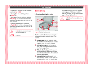 14
14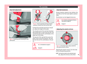 15
15 16
16 17
17 18
18 19
19 20
20 21
21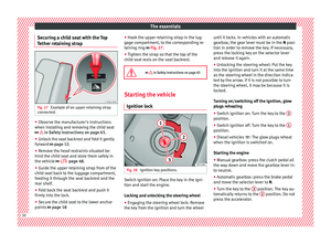 22
22 23
23 24
24 25
25 26
26 27
27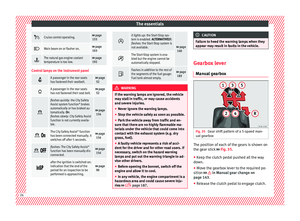 28
28 29
29 30
30 31
31 32
32 33
33 34
34 35
35 36
36 37
37 38
38 39
39 40
40 41
41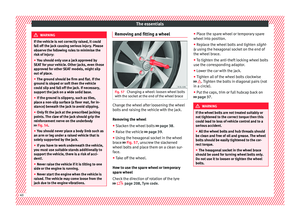 42
42 43
43 44
44 45
45 46
46 47
47 48
48 49
49 50
50 51
51 52
52 53
53 54
54 55
55 56
56 57
57 58
58 59
59 60
60 61
61 62
62 63
63 64
64 65
65 66
66 67
67 68
68 69
69 70
70 71
71 72
72 73
73 74
74 75
75 76
76 77
77 78
78 79
79 80
80 81
81 82
82 83
83 84
84 85
85 86
86 87
87 88
88 89
89 90
90 91
91 92
92 93
93 94
94 95
95 96
96 97
97 98
98 99
99 100
100 101
101 102
102 103
103 104
104 105
105 106
106 107
107 108
108 109
109 110
110 111
111 112
112 113
113 114
114 115
115 116
116 117
117 118
118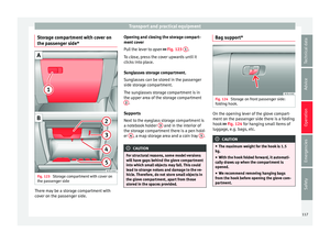 119
119 120
120 121
121 122
122 123
123 124
124 125
125 126
126 127
127 128
128 129
129 130
130 131
131 132
132 133
133 134
134 135
135 136
136 137
137 138
138 139
139 140
140 141
141 142
142 143
143 144
144 145
145 146
146 147
147 148
148 149
149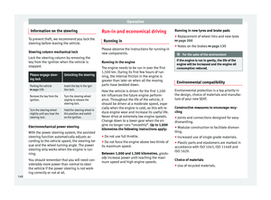 150
150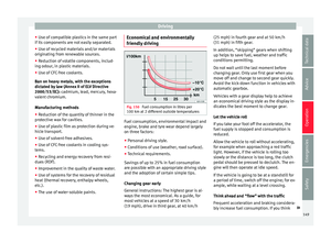 151
151 152
152 153
153 154
154 155
155 156
156 157
157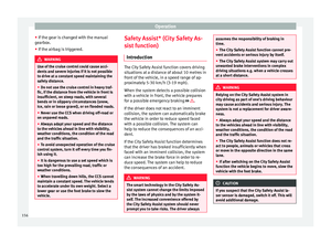 158
158 159
159 160
160 161
161 162
162 163
163 164
164 165
165 166
166 167
167 168
168 169
169 170
170 171
171 172
172 173
173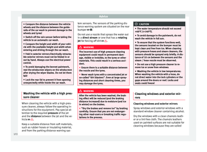 174
174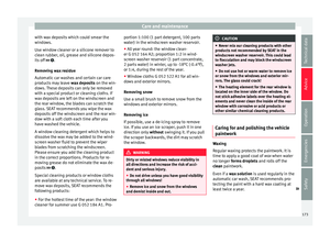 175
175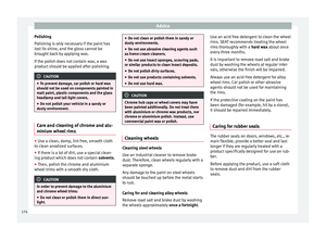 176
176 177
177 178
178 179
179 180
180 181
181 182
182 183
183 184
184 185
185 186
186 187
187 188
188 189
189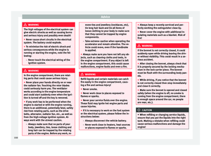 190
190 191
191 192
192 193
193 194
194 195
195 196
196 197
197 198
198 199
199 200
200 201
201 202
202 203
203 204
204 205
205 206
206 207
207 208
208 209
209 210
210 211
211 212
212 213
213 214
214 215
215 216
216 217
217 218
218 219
219 220
220 221
221 222
222 223
223 224
224 225
225 226
226 227
227 228
228 229
229 230
230 231
231