Page 89 of 232

General instrument panel
Operation
Gener a
l
instrument panel
Instrument panel Key to
Fig. 94:
Door rel e
ase lever . . . . . . . . . . . . . . . . 98
Turn switch for adjusting the exteri-
or mirrors . . . . . . . . . . . . . . . . . . . . . . . . 110
– Exterior mirr or a
djustment
– Heated exterior mirrors
Air outlets . . . . . . . . . . . . . . . . . . . . . . . . 129
Lever for . . . . . . . . . . . . . . . . . . . . . . . . . 103
– Turn sign
als and main beam
headlights
– Cruise control system (CCS) –
– – /+ – /- . . . . . . .155
Steering wheel with horn and – Driver airb ag . . . . . . . . . . . . . . . . . . . 14
Da
sh panel . . . . . . . . . . . . . . . . . . . . . . . 88, 25
Windscreen wiper/ windscreen
wash l
ever . . . . . . . . . . . . . . . . . . . . . . . 108
– Wind s
creen wipers
– Rear window wiper
1 2
3
4
5
6
7 –
Lev
er w
ith buttons for controlling
the SEAT information system –
/ . . . . . . . . . . . . . . . . . . . . . . . . . 23
Controls for:
– Start
-Stop system button . . .160
– Rear w
indow heating button . .129
– Left
seat heating controls . . . . . 113
Switches for: – Heating and
ventilation system .129
– Manual air c
onditioning . . . . . . . . . 129
– Clim atr
onic . . . . . . . . . . . . . . . . . . . . . 129
Radio (factory fitted) ›››
Booklet Ra-
dio
Controls for:
– Hazard warning lights switch
. . . . . . . . . . . . . . . . . . . . . . . . . . . . . . 70
– Pa s
senger front airbag off warn-
ing lamp . .58
– Right seat
heating controls
or rear window heating button
(alternative position) . . . . . . . . . . .113, 129
Storage compartment with drink
hol der in the c
entre console . . . . . . .119
Handle of the storage compartment
or stor
age compartment open 1)
. . . 115
8 9
10
11
12
13 In the side of the dash panel: Key
sw
it
c
h for switching off the front
passenger airbag 1)
. . . . . . . . . . . . . . . 58
Position of passenger front airbag
on the dash p
anel . . . . . . . . . . . . . . . . 58
Ashtray* . . . . . . . . . . . . . . . . . . . . . . . . . 120
12 volt socket or cigarette light-
er* . . . . . . . . . . . . . . . . . . . . . . . . . . . . . . . 120, 120
Lever for:
– Manual g
earbox . . . . . . . . . . . . . . . . 143
– Autom atic
gearbox . . . . . . . . . . . . . 144
Handbrake . . . . . . . . . . . . . . . . . . . . . . . 135
Button for:
– City
Safety Assist function
. . . . . . . . . . . . . . . . . . . . . . . . . . . 156
Ignition lock . . . . . . . . . . . . . . . . . . . . . . 133
Pedals . . . . . . . . . . . . . . . . . . . . . . . . . . . 142
Storage compartment . . . . . . . . . . . . .115
Steering column adjustment lev-
er . . . . . . . . . . . . . . . . . . . . . . . . . . . . . . . . 48
Open bonnet lever . . . . . . . . . . . . . . . . 187
Headlight range control . . . . . . . . 103
Light switch . . . . . . . . . . . . . . . . . . . 103
Central locking button . . . . . .94
Buttons for operating the front elec-
tric windo
ws . . . . . . . . . . . . . . . . . . . 101 14
15
16
17
18
19
20
21
22
23
24
25
26
27
28
29
1)
According to version
87
Technical data
Advice
Operation
Emergencies
Safety
Page 90 of 232
 and variant 2 (B). Details of the instruments
››
›
Fig. 95:
Speedometer. Depending on")
Operation
Instruments V iew of
in
strument panelFig. 95
Instrument panel, on dash panel: variant 1 (A) and variant 2 (B). Details of the instruments
››
›
Fig. 95:
Speedometer. Depending on the
vehicle in km/h or in mph.
Displays on the screen . . . . . . . . . . . . 89
Reset knob for trip rec
order (trip).
– Press the button 0.0/SET bri
efly to
sw it
ch the trip odometer and od-
ometer.
1 2
3 –
Pr e
s
s the 0.0/SET for
5 seconds
t
o
r
eset the odometer to zero and,
where necessary, other indicators
on the multifunction display. . . . .23
Fuel reserve display . . . . . . . . . . . . . . . 183
Rev counter (with the engine ru
n-
ning, in thousands of revolutions
per minute).
The beginning of the red zone of
the rev counter indicates the maxi-
4 5 mum speed in any gear after run-
nin
g
-in and w
ith the engine hot.
However, it is advisable to change
up a gear or move the selector lever
to D (or lift your foot off the acceler-
ator) before the needle reaches the
red zone ››› .
C loc
k
set button .
– If necessary, change the time dis-
play by pressing the top and
6
88
Page 91 of 232

General instrument panel
bottom buttons of the rocker
sw it
c
h ›››
Fig. 33
B .
– Pr e
s
s the button to change the
hour, so that it is flashing.
– To continue setting the time,
press button 0.0/SET . Hold button
do wn t
o s
croll through the num-
bers quickly.
– Press the button again to
change the minutes, so that it
flashes.
– To continue setting the time,
press button 0.0/SET . Hold button
do wn t
o s
croll through the num-
bers quickly.
– Press the button again to end
the clock setting. CAUTION
● When the engine i s
cold, avoid high revs
and heavy acceleration and do not make the
engine work hard.
● To prevent damage to the engine, the rev
count
er needle should only remain in the red
zone for a short period of time. For the sake of the environment
Changing up a gear in time reduces fuel con-
sumption and noi se. Indications on the display
A variety of information can be viewed on the
ins
trument
panel display ››› Fig. 95 2 , de-
pending on the v
ehicle equipment:
● Warning and information messages.
● Odometer.
● Time.
● Outside temperature.
● Selector lever positions ›››
page 142.
● Recommended gear (manual gearbox)
›› ›
page 142.
● Multifunction display (MFI) ›››
page 23
● Service interval display ›››
page 90 .
● Start-Stop system status display
›››
page 160.
● Fuel gauge ›››
page 183.
● Seat belt status display for rear seats
›››
page 52.
Warning and information messages
The system runs a check on certain compo-
nents and functions when the ignition is
switched on and while the vehicle is moving.
Faults in the operation are displayed on the
screen using red and yellow symbols on the
instrument panel display ( ›››
page 25)
and, in some cases, with audible warnings.
The display may vary according to the type of
instrument panel fitted.
Priority 1 warning (red symbols)
Symbol flashing or lit; partly combined with audible
warnings.
Stop the vehicle! It is dangerous ››› !
Check the function that is faulty and repair it. If necessa-
ry, request assistance from specialised personnel.
Priority 2 warning (yellow symbols)
Symbol flashing or lit; partly combined with audible
warnings.
A faulty function, or fluids which are below the correct
levels may cause damage to the vehicle! ›››
Check the faulty function as soon as possible. If neces-
sary, request assistance from specialised personnel. Odometer
The odomet
er
r
egisters the total distance
travelled by the car.
The odometer (trip ) shows the distance
travelled since the last odometer reset. The
last figure indicates 100 m.
Outside temperature indicator!
When the outside temperature is below +4°C
(+39°F), the “ice crystal” symbol (warning of
risk of freezing) is also displayed next to the
temperature. At first this symbol flashes and
then it remains lit until the outside tempera-
ture rises above +6°C (+43°F) ››› .
When the v
ehic
le is stationary or travelling at
very low speeds, the temperature displayed
may be slightly higher than the actual »
89
Technical data
Advice
Operation
Emergencies
Safety
Page 92 of 232
.
Selector lever position
The range of engaged g")
Operation
outside temperature as a result of heat com-
in g fr
om the en
gine.
The temperatures measured range from
-40°C to +50°C (-40°F to +122°F).
Selector lever position
The range of engaged gears of the selector
lever is shown on the side of the lever, and
on the instrument panel display. In positions
D and M, and with the Tiptronic, the corre-
sponding gear is also indicated on the dis-
play.
Recommended gear* (manual gearbox)
The recommended gear to save fuel can be
displayed on the instrument panel display
while you are driving ››› page 142.
Seat belt status display for the rear seats*
The seat belt status display on the instru-
ment panel display informs the driver, when
the ignition is switched on, whether any pas-
sengers in the rear seats have fastened their
seat belts ››› page 52.
Start-Stop system status display
The instrument panel display shows informa-
tion on the current status ››› page 160. WARNING
If the warning lamps are ignored, the vehicle
ma y
stall in traffic, or may cause accidents
and severe injuries.
● Never ignore the warning lamps.
● Stop the vehicle safely as soon as possible.
● A faulty vehicle represents a risk of acci-
dent for the driv
er and for other road users. If
necessary, switch on the hazard warning
lamps and put out the warning triangle to ad-
vise other drivers.
● Park the vehicle away from traffic and en-
sure th
at no highly flammable materials are
under the vehicle that could come into con-
tact with the exhaust system (e.g. dry grass,
fuel). WARNING
Even though outside temperatures are above
freez in
g, some roads and bridges may be icy.
● At outside temperatures above +4°C
(+39°F), even when the “ice c
rystal” symbol
is not visible, there may still be patches of ice
on the road.
● Do not rely on the outside temperature in-
dicator! CAUTION
Failure to heed the warning lamps when they
appe ar m
ay result in faults in the vehicle. Note
● Differ ent
versions of the instrument panel
are available and therefore the versions and
instructions on the display may vary.
● When several warnings are active at the
same time, the symbol
s are shown succes-
sively for a few seconds and will stay on until
the fault is rectified. Service interval display
The inspection message appears on the in-
s
trument
p
anel display ›››
Fig. 95 2 .
S EA
T di
stinguishes between services with en-
gine oil change (Oil Change Service) and
services without engine oil change (Inspec-
tion Service). The service interval display only
gives information for service dates which in-
volve an engine oil change. The dates of the
remaining services (e.g. the next Inspection
Service or change of brake fluid) are listed on
the label attached to the door strut, or in the
Maintenance Programme.
The set service intervals have been specified
with the service dependent on time/distance
travelled.
Inspection reminder
If the inspection period is due to expire
shortly, Inspection reminder appears when
starting the ignition abbreviated to
and a
90
Page 93 of 232
General instrument panel
warning in km . The number of
k ilometres
shown is the maximum number that may be
driven until the next service.
Service due
After the service date, an audible warning is
given when the ignition is switched on and
the abbreviation displayed on the screen
flashes for a few seconds. Note
The service message disappears after a few
second s, when the en
gine is started or when
OK is pressed on the windscreen wiper lever.
Note
In vehicles whose batteries have been dis-
connect ed f
or a long period of time, it will not
be possible to calculate the next service date.
Therefore the service interval display may not
be correct. In this case, bear in mind the max-
imum service intervals permitted in the
››› Booklet Maintenance Programme. 91
Technical data
Advice
Operation
Emergencies
Safety
Page 94 of 232

Operation
Opening and closing V ehic
l
e key set
Remote control vehicle key* Fig. 96
Remote control key Remote control key
W
ith the
v
ehicle key the vehicle may be
locked or unlocked remotely ››› page 94.
The vehicle key includes an emitter and bat-
tery. The receiver is in the interior of the vehi-
cle. The range of the vehicle key with remote
control and new battery is several metres
around the vehicle.
If it is not possible to open or close the vehi-
cle using the remote control key, this should
be re-synchronised ››› page 94 or the bat-
tery changed ››› page 93. Different keys belonging to the vehicle may
be used.
Fo
lding the key shaft in and out
When the button is pressed ››› Fig. 96 A , the
k ey
sh
aft is released and unfolds.
To fold it press the button and fold the key
shaft in until it locks in place.
Spare key
To obtain a spare key and other vehicle keys,
the vehicle chassis number is required.
Each new key must contain a microchip and
be coded with the data from the vehicle elec-
tronic immobiliser. A vehicle key will not work
if it does not contain a microchip or the mi-
crochip has not been encoded. This is also
true for keys cut for the vehicle.
The vehicle keys or new spare keys can be
obtained from a SEAT dealership, a Special-
ised workshop or approved key service quali-
fied to create this kind of key.
New keys or spare keys must be synchron-
ised before use ››› page 94. WARNING
Careless or incorrect use of vehicle keys may
re s
ult in severe injury and accident.
● Always take all the keys with you whenever
you le
ave the vehicle. Children and unauthor-
ised individuals could lock the doors or the boot hatch, start the engine or turn on the ig-
nition, activatin
g el
ectrical systems, the elec-
tric windows, for example.
● Never leave children or disabled people
alone in the car
. They could be trapped in the
car in an emergency and will not be able to
get themselves to safety. For example, de-
pending on the time of the year, tempera-
tures inside a locked and closed vehicle can
be extremely high or extremely low resulting
in serious injuries and illness or even death,
particularly for young children.
● Never remove the key from the ignition if
the vehic
le is in motion. The steering may
lock and it will not be possible to turn the
steering wheel. CAUTION
The remote control key contains electronic
component s. Pr
otect them from damage, im-
pacts and humidity. Note
● Only u
se the key button when you require
the corresponding function. Pushing the but-
ton unnecessarily could accidentally unlock
the vehicle or trigger the alarm. It is also pos-
sible even when you are outside the radius of
action.
● Remote control key operation can be great-
ly influenced b
y overlapping radio signals
around the vehicle working in the same range 92
Page 95 of 232
.
● Obstacles between the remote control and
the vehic
le, bad weather conditions and
draining batteries can")
Opening and closing
of frequencies (for example, radio
tran
smitt
ers, mobile telephones).
● Obstacles between the remote control and
the vehic
le, bad weather conditions and
draining batteries can considerably reduce
the range of the remote control.
● If the buttons of the vehicle key are press-
ed ›››
Fig. 96 or one of the central locking but-
tons ››› page 94 is pressed repeatedly in
quick succession, the central locking briefly
disconnects as protection against overload-
ing. The vehicle is then unlocked. Lock it if necessary. Mechanical vehicle key
Fig. 97
Vehicle mechanical key The vehicle key set may include a mechanical
k
ey
›
›› Fig. 97. Duplicate keys
To obt
ain a spare key and other vehicle keys,
the vehicle chassis number is required.
Each new key must contain a microchip and
be coded with the data from the vehicle elec-
tronic immobiliser. A vehicle key will not work
if it does not contain a microchip or the mi-
crochip has not been encoded. This is also
true for keys cut for the vehicle.
The vehicle keys or new spare keys can be
obtained from a SEAT dealership, a special-
ised workshop or an approved locksmith
qualified to create them.
Control lamp on the vehicle key Fig. 98
Control lamp on the vehicle key When a button on the vehicle key is pressed,
the c
ontr
o
l lamp flashes ››› Fig. 98 (arrow)
once briefly. If the button is pressed and
held, the indicator blinks several times, for example: for the convenience opening func-
tion.
When the contro
l lamp does not light upon
pushing a button, the vehicle key batteries
must be changed ››› page 93.
Replacing the battery Fig. 99
Vehicle key: battery compartment cov-
er Fig. 100
Vehicle key: removing the battery » 93
Technical data
Advice
Operation
Emergencies
Safety
Page 96 of 232

Operation
SEAT recommend having the batteries
c h
an
ged in a specialised workshop.
The battery is located to the rear of the vehi-
cle key, under a cover.
Changing the battery
● Unfold the vehicle key blade ›››
page 92.
● Remove the cover from the back of the ve-
hicle k
ey ››› Fig. 99 in the direction of the ar-
row ››› .
● Extract the battery from the compartment
u s
in
g a suitable thin object ››› Fig. 100.
● Place the new battery in the compartment,
pres
sing in the direction of the arrow as
shown ››› Fig. 100 ››› .
● Fit the battery compartment cover, pressing
in the dir ection of
the arr
ow as shown
››› Fig. 99 until it clicks into place. CAUTION
● If the b att
ery is not changed correctly, the
vehicle key may be damaged.
● Use of unsuitable batteries may damage
the vehic
le key. For this reason, always re-
place the dead battery with another of the
same voltage, size and specifications.
● When fitting the battery, check that the po-
larity i
s correct. For the sake of the environment
Please dispose of your used batteries correct-
ly and w ith r
espect for the environment. Synchronising the vehicle key
If the
button is pressed frequently outside
of the
vehicle range, it is possible that the ve-
hicle can no longer be locked or unlocked us-
ing the key. In this case, the vehicle key must
be synchronised once more as follows:
● Unfold the vehicle key blade ››
›
page 92.
● Press the button on the
vehicle key. For
this, it must remain with the vehicle.
● Open the vehicle within one minute using
the key sh
aft.
● Turn on the ignition using the vehicle key.
The key h
as been synchronised.
● If necessary, fit the cap.
Central locking* and locking
syst
em
Introduction Read the additional information carefully
› ›
›
page 8 Central locking functions correctly when all
the doors and the r
ear lid are correctly shut.
If the driver door is open, the vehicle cannot
be locked with the key.
The battery of an unlocked vehicle parked for
a long period (e.g. in a private garage) may
run down and fail to start the motor. WARNING
The incorrect use of the central locking sys-
tem m a
y cause serious injuries.
● The central locking system will lock all
doors. A v
ehicle locked from the inside can
prevent any non-authorised individual from
opening the doors and accessing the vehicle.
Nevertheless, in case of emergency or acci-
dent, locked doors will complicate access to
the vehicle interior to help the passengers.
● Never leave children or disabled people
alone in the v
ehicle. The central locking but-
ton can be used to lock all the doors from
within. Therefore, passengers will be locked
inside the vehicle. Individuals locked in the
vehicle can be exposed to very high or very
low temperatures.
● Depending on the time of the year, temper-
ature
s inside a locked and closed vehicle can
be extremely high or extremely low resulting
in serious injuries and illness or even death,
particularly for young children.
● Never leave individuals locked in a closed
and locked
vehicle. In case of emergency,
they may not be able to exit the vehicle by
themselves or get help. 94
 1
1 2
2 3
3 4
4 5
5 6
6 7
7 8
8 9
9 10
10 11
11 12
12 13
13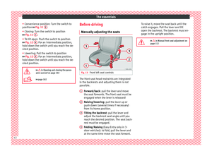 14
14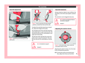 15
15 16
16 17
17 18
18 19
19 20
20 21
21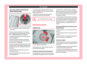 22
22 23
23 24
24 25
25 26
26 27
27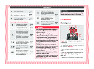 28
28 29
29 30
30 31
31 32
32 33
33 34
34 35
35 36
36 37
37 38
38 39
39 40
40 41
41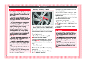 42
42 43
43 44
44 45
45 46
46 47
47 48
48 49
49 50
50 51
51 52
52 53
53 54
54 55
55 56
56 57
57 58
58 59
59 60
60 61
61 62
62 63
63 64
64 65
65 66
66 67
67 68
68 69
69 70
70 71
71 72
72 73
73 74
74 75
75 76
76 77
77 78
78 79
79 80
80 81
81 82
82 83
83 84
84 85
85 86
86 87
87 88
88 89
89 90
90 91
91 92
92 93
93 94
94 95
95 96
96 97
97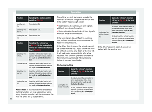 98
98 99
99 100
100 101
101 102
102 103
103 104
104 105
105 106
106 107
107 108
108 109
109 110
110 111
111 112
112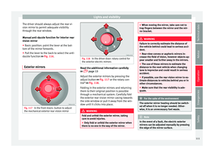 113
113 114
114 115
115 116
116 117
117 118
118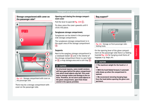 119
119 120
120 121
121 122
122 123
123 124
124 125
125 126
126 127
127 128
128 129
129 130
130 131
131 132
132 133
133 134
134 135
135 136
136 137
137 138
138 139
139 140
140 141
141 142
142 143
143 144
144 145
145 146
146 147
147 148
148 149
149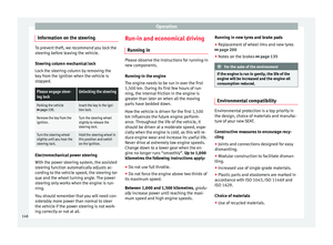 150
150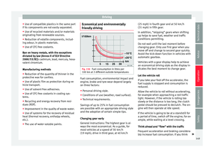 151
151 152
152 153
153 154
154 155
155 156
156 157
157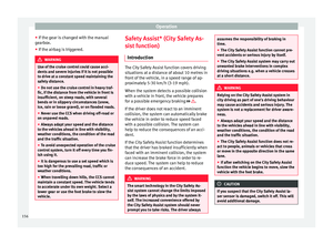 158
158 159
159 160
160 161
161 162
162 163
163 164
164 165
165 166
166 167
167 168
168 169
169 170
170 171
171 172
172 173
173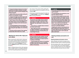 174
174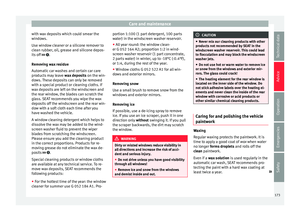 175
175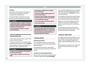 176
176 177
177 178
178 179
179 180
180 181
181 182
182 183
183 184
184 185
185 186
186 187
187 188
188 189
189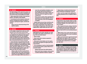 190
190 191
191 192
192 193
193 194
194 195
195 196
196 197
197 198
198 199
199 200
200 201
201 202
202 203
203 204
204 205
205 206
206 207
207 208
208 209
209 210
210 211
211 212
212 213
213 214
214 215
215 216
216 217
217 218
218 219
219 220
220 221
221 222
222 223
223 224
224 225
225 226
226 227
227 228
228 229
229 230
230 231
231