Page 41 of 114

Instrument and control functions
3-26
3
3. Wipe up any spilled fuel immedi- ately. NOTICE: Immediately
wipe off spille d fuel with a clean,
d ry, soft cloth, since fuel may
d eteriorate painte d surfaces or
plastic parts.
[ECA10072]
4. Be sure to securely close the fuel tank cap.
WARNING
EWA15152
Gasoline is poisonous an d can cau-
se injury or death. Han dle gasoline
with care. Never siphon gasoline by
mouth. If you shoul d swallow some
g asoline or inhale a lot of gasoline
vapor, or get some g asoline in your
eyes, see your d octor immediately. If g
asoline spills on your skin, wash
with soap an d water. If gasoline
spills on your clothin g, chan ge your
clothes.
EAU58111
NOTICE
ECA11401
Use only unlea ded g asoline. The use
of lead ed g asoline will cause severe
d amag e to internal en gine parts,
such as the valves an d piston rin gs,
as well as to the exhaust system.Your Yamaha engine has been de-
signed to use premium unleaded gas-
oline with a research octane number of
95 or higher. If knocking (or pinging)
occurs, use a gasoline of a different brand. Use of unleaded fuel will extend
spark plug life and reduce mainte-
nance costs.
Gasohol
There are two types of gasohol: gaso-
hol containing ethanol and that con-
taining methanol. Gasohol containing
ethanol can be used if the ethanol con-
tent does not exceed 10% (E10). Gas-
ohol containing methanol is not
recommended by Yamaha because it
can cause damage to the fuel system
or vehicle performance problems.
1. Fuel tank filler tube
2. Maximum fuel level
1
2
Recommen
ded fuel:
Premium unleaded gasoline (Gaso-
hol [E10] acceptable)
Fuel tank capacity:
18 L (4.8 US gal, 4.0 Imp.gal)
Fuel reserve amount: 2.6 L (0.69 US gal, 0.57 Imp.gal)
U2PPE2E0.book Page 26 Tuesday, June 9, 2015 1:57 PM
Page 42 of 114

Instrument and control functions
3-27
3
EAU51193
Fuel tank breather hose an d
overflow hoseBefore operating the motorcycle:
Check each hose connection.
Check each hose for cracks or
damage, and replace if necessary.
Make sure that the end of each
hose is not blocked, and clean if
necessary.
Make sure that each hose is rout-
ed through the clamp.
EAU13434
Catalytic converterThis model is equipped with a catalytic
converter in the exhaust system.
WARNING
EWA10863
The exhaust system is hot after op-
eration. To prevent a fire hazar d or
b urns:
Do not park the vehicle near
possi ble fire hazard s such as
g rass or other materials that
easily burn.
Park the vehicle in a place
where ped estrians or chil dren
are not likely to touch the hot
exhaust system.
Make sure that the exhaust sys-
tem has coole d down before
d oin g any maintenance work.
Do not allow the en gine to id le
more than a few minutes. Lon g
i d lin g can cause a b uild-up of
heat.
NOTICE
ECA10702
Use only unlea ded g asoline. The use
of lead ed g asoline will cause unre-
pairab le damag e to the catalytic
converter.
1. Fuel tank breather hose and overflow hose
2. Clamp
21
U2PPE2E0.book Page 27 Tuesday, June 9, 2015 1:57 PM
Page 43 of 114

Instrument and control functions
3-28
3
EAU65800
SeatsPassen ger seat
To remove the passenger seat1. Insert the key into the seat lock, and then turn it counterclockwise.
2. Lift the front of the passenger seat and pull it forward.
To install the passenger seat1. Insert the projections on the rear of the passenger seat into the seat
holders as shown, and then push
the front of the seat down to lock
it in place. 2. Remove the key.
Ri der seat
To remove the rider seat
1. Remove the passenger seat.
2. Remove the cap, then push the rider seat lock lever, located under
the back of the rider seat, to the
left as shown, and then pull the
seat off. To install the rider seat
1. Install the cap with the arrow mark
facing forward.
2. Insert the projection on the front of the rider seat into the seat holder
as shown, and then push the rear
of the seat down to lock it in place.
1. Seat lock
2. Unlock.
1
2
1. Projection
2. Seat holder
1 2
1. Cap
2. Rider seat lock lever
2
1
U2PPE2E0.book Page 28 Tuesday, June 9, 2015 1:57 PM
Page 44 of 114
Instrument and control functions
3-29
3
3. Install the passenger seat.
TIPMake sure that the seats are prop-
erly secured before riding.
The rider seat height can be ad-
justed to change the riding posi-
tion. (See the following section.)
EAU63050
Adjustin g the ri der seat hei ghtThe rider seat height can be adjusted
to one of two positions to suit the rid-
er’s preference.
The rider seat height was adjusted to
the lower position at delivery.
To chan ge the ri der seat hei ght to
the hi gh position
1. Remove the passenger seat and rider seat. (See page 3-28.)
2. Remove the rider seat height posi- tion adjuster by pulling it upward. 3. Install the rider seat height posi-
tion adjuster by inserting the front
projections into the grommets.
1. Projection
2. Seat holder
2 1
1. Low position
2. High position
1
2
1. Rider seat height position adjuster
1. Rider seat height position adjuster
2. Projection
3. Grommet
1
1
2
3
3
U2PPE2E0.book Page 29 Tuesday, June 9, 2015 1:57 PM
Page 45 of 114
Instrument and control functions
3-30
3
4. Insert the projection on the front of
the rider seat into seat holder B as
shown.
5. Align the projection on the bottom of the rider seat with the “H” posi-
tion slot, and then push the rear of
the seat down to lock it in place as
shown. 6. Install the passenger seat.
To chan ge the ri der seat hei ght to
the low position 1. Remove the passenger seat and rider seat. (See page 3-28.)
2. Remove the rider seat height posi- tion adjuster by pulling it upward.
3. Install the rider seat height posi- tion adjuster by inserting the rear
projections into the grommets. 4. Insert the projection on the front of
the rider seat into seat holder A as
shown.
1. Projection
2. Seat holder B (for high position)
2 1
2
1. Projection
2. “H” position slot
1
2
1. Rider seat height position adjuster
2. Projection
3. Grommet
1. Projection
2. Seat holder A (for low position)
1
2
3
3
2 1
2
U2PPE2E0.book Page 30 Tuesday, June 9, 2015 1:57 PM
Page 46 of 114

Instrument and control functions
3-31
3 5. Align the projection on the bottom
of the rider seat with the “L” posi-
tion slot, and then push the rear of
the seat down to lock it in place as
shown.
6. Install the passenger seat.
TIPMake sure that the seats are properly
secured before riding.
EAU63060
Helmet hold erThe helmet holder is located under the
passenger seat. A helmet holding ca-
ble is provided in the owner’s tool kit to
secure a helmet to the helmet holder.
To secure a helmet to the helmet
holder
1. Remove the passenger seat. (See page 3-28.)
2. Pass the helmet holding cable through the buckle on the helmet
strap as shown, and then hook the
cable loops over the helmet hold-
er. 3. Place the helmet on the right side
of the vehicle, and then install the
seat. WARNING! Never ri de with
a helmet attached to the helmet
hol der, since the helmet may hit
o bjects, causin g loss of control
an d possi bly an acci dent.
[EWA10162]
To release the helmet from the hel-
met hol der
Remove the passenger seat, remove
the helmet holding cable from the hel-
met holder and the helmet, and then in-
stall the seat.
1. Projection
2. “L” position slot
1
2
1. Helmet
2. Helmet holding cable
3. Helmet holder
3
2
1
U2PPE2E0.book Page 31 Tuesday, June 9, 2015 1:57 PM
Page 47 of 114

When storing documents or other
items in the storage")
Instrument and control functions
3-32
3
EAU14465
Stora ge compartmentThe storage compartment is located
under the passenger seat. (See page
3-28.)
When storing documents or other
items in the storage compartment, be
sure to wrap them in a plastic bag so
that they will not get wet. When wash-
ing the vehicle, be careful not to let any
water enter the storage compartment.
WARNING
EWA10962
Do not exceed the load limit of 3
k g (7 l b) for the stora ge com-
partment.
Do not exceed the maximum
loa d of 180 k g (397 l b) for the ve-
hicle.
EAU63070
Win dshieldTo suit the rider’s preference, the wind-
shield can be changed to one of three
positions.
To a djust the win dshiel d hei ght
1. Loosen the windshield height po- sition adjusting knob on each side
of the windshield until resistance
is felt. NOTICE: Do not continue
turning the kno b after resis-
tance is felt. Otherwise, the
kno b coul d b e damag ed .
[ECA20211]
2. Align the slide plate holder on the
left side of the windshield with the
match mark at the desired posi-
tion.
1. Storage compartment
1
1. Windshield height position adjusting knob
1
U2PPE2E0.book Page 32 Tuesday, June 9, 2015 1:57 PM
Page 48 of 114

Instrument and control functions
3-33
3
TIPMake sure that the projection on the
slide plate holder fits into the corre-
sponding hole in the slide plate.3. Tighten the adjusting knobs.
EAU62450
A djustin g the front fork
WARNING
EWA14671
Always a djust the sprin g preloa d on
b oth fork leg s equally, otherwise
poor han dlin g an d loss of sta bility
may result.Each front fork leg is equipped with a
spring preload adjusting bolt. The right
front fork leg is equipped with a re-
bound damping force adjusting screw.NOTICE
ECA10102
To avoi d d amag ing the mechanism,
d o not attempt to turn b eyond the
maximum or minimum setting s.Spring preloa d
To increase the spring preload and
thereby harden the suspension, turn
the adjusting bolt on each fork leg in di-
rection (a). To decrease the spring pre-
load and thereby soften the
suspension, turn the adjusting bolt on
each fork leg in direction (b). The spring preload setting is deter-
mined by measuring distance A,
shown in the illustration. The shorter
distance A is, the higher the spring pre-
load; the longer distance A is, the lower
the spring preload.
1. Match mark
2. Slide plate
3. Slide plate holder
2
13
1. Spring preload adjusting bolt
1. Distance A
1
1
(a)
(b)
(a)
(b)
1
U2PPE2E0.book Page 33 Tuesday, June 9, 2015 1:57 PM
 1
1 2
2 3
3 4
4 5
5 6
6 7
7 8
8 9
9 10
10 11
11 12
12 13
13 14
14 15
15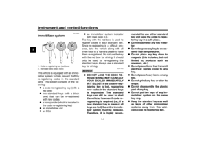 16
16 17
17 18
18 19
19 20
20 21
21 22
22 23
23 24
24 25
25 26
26 27
27 28
28 29
29 30
30 31
31 32
32 33
33 34
34 35
35 36
36 37
37 38
38 39
39 40
40 41
41 42
42 43
43 44
44 45
45 46
46 47
47 48
48 49
49 50
50 51
51 52
52 53
53 54
54 55
55 56
56 57
57 58
58 59
59 60
60 61
61 62
62 63
63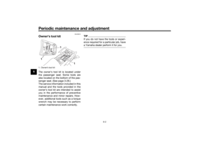 64
64 65
65 66
66 67
67 68
68 69
69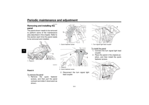 70
70 71
71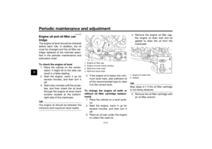 72
72 73
73 74
74 75
75 76
76 77
77 78
78 79
79 80
80 81
81 82
82 83
83 84
84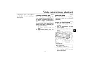 85
85 86
86 87
87 88
88 89
89 90
90 91
91 92
92 93
93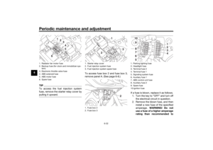 94
94 95
95 96
96 97
97 98
98 99
99 100
100 101
101 102
102 103
103 104
104 105
105 106
106 107
107 108
108 109
109 110
110 111
111 112
112 113
113
