Page 17 of 114

Instrument and control functions
3-2
3
Keep other immo bilizer system
keys away from the main switch
as they may cause si gnal inter-
ference.
EAU10474
Main switch/steerin g lockThe main switch/steering lock controls
the ignition and lighting systems, and is
used to lock the steering. The various
positions are described below.TIPBe sure to use the standard key (black
bow) for regular use of the vehicle. To
minimize the risk of losing the code re-
registering key (red bow), keep it in a
safe place and only use it for code re-
registering.
EAU10551
ON
All electrical circuits are supplied with
power, the meter lighting, taillight, li-
cense plate light and auxiliary lights
come on, and the engine can be start-
ed. The key cannot be removed.TIPThe headlights come on automatically
when the engine is started and stay on
until the key is turned to “OFF”, even if
the engine stalls.
EAU10662
OFF
All electrical systems are off. The key
can be removed.
WARNING
EWA10062
Never turn the key to “OFF” or
“LOCK” while the vehicle is movin g.
Otherwise the electrical systems will
b e switche d off, which may result in
loss of control or an acci dent.
P
ON
OFF
LOCK
U2PPE2E0.book Page 2 Tuesday, June 9, 2015 1:57 PM
Page 18 of 114
Instrument and control functions
3-3
3
EAU10686
LOCK
The steering is locked and all electrical
systems are off. The key can be re-
moved.
To lock the steering1. Turn the handlebars all the way to
the left.
2. With the key in the “OFF” position, push the key in and turn it to
“LOCK”.
3. Remove the key.
TIPIf the steering will not lock, try turning
the handlebars back to the right slight-
ly.To unlock the steering1. Insert the key.
2. With the key in the “LOCK” posi- tion, push the key in and turn it to
“OFF”.
EAU59680
(Parkin g)
The hazard lights and turn signal lights
can be turned on, but all other electri-
cal systems are off. The key can be re-
moved. The steering must be locked before the
key can be turned to “ ”.
NOTICE
ECA20760
Usin
g the hazar d o r tu r n s i gnal li ghts
for an exten ded len gth of time may
cause the battery to dischar ge.
1. Push.
2. Turn.12
1. Push.
2. Turn.12
U2PPE2E0.book Page 3 Tuesday, June 9, 2015 1:57 PM
Page 19 of 114

Instrument and control functions
3-4
3
EAU49398
In dicator lig hts and warning
lig hts
EAU11032
Turn si gnal in dicator li ghts “ ”
an d“”
Each indicator light will flash when its
corresponding turn signal lights are
flashing.
EAU11061
Neutral in dicator li ght “ ”
This indicator light comes on when the
transmission is in the neutral position.
EAU11081
Hi gh beam in dicator li ght “ ”
This indicator light comes on when the
high beam of the headlight is switched
on.
EAU11256
Oil level warnin g lig ht “ ”
This warning light comes on if the en-
gine oil level is low.
The electrical circuit of the warning
light can be checked by turning the key
to “ON”. The warning light should
come on for a few seconds and then
go off.
If the warning light does not come on
initially when the key is turned to “ON”,
or if the warning light remains on after
confirming that the oil level is correct
(see page 6-10), have a Yamaha dealer
check the vehicle.
TIP Even if the oil level is sufficient, the
warning light may flicker when rid-
ing on a slope or during sudden
acceleration or deceleration, but
this is not a malfunction.
This model is equipped with a self-
diagnosis device for the oil level
detection circuit. If a problem is
detected in the oil level detection
circuit, the oil level warning light
will flash repeatedly. If this occurs,
have a Yamaha dealer check the
vehicle.
EAU46443
Engine trou ble warnin g li ght “ ”
This warning light comes on if a prob-
lem is detected in the electrical circuit
monitoring the engine. If this occurs,
have a Yamaha dealer check the self-
diagnosis system. (See page 3-17 for
an explanation of the self-diagnosis
device.)
The electrical circuit of the warning
light can be checked by turning the key
to “ON”. The warning light should
come on for a few seconds, and then
go off.
1. Left turn signal indicator light “ ”
2. Right turn signal indicator light “ ”
3. Oil level warning light “ ”
4. Engine trouble warning light “ ”
5. Anti-lock Brake System (ABS) warning light “ ”
6. Traction control system indicator/warning light “TCS”
7. High beam indicator light “ ”
8. Neutral indicator light “ ”
9. Immobilizer system indicator light “ ”
GEARN
25
A.TEMP ˚C
Lo
C.TEMP ˚C
0:00
TIME TRIP
3456
789
1
2
ABS
U2PPE2E0.book Page 4 Tuesday, June 9, 2015 1:57 PM
Page 20 of 114

Instrument and control functions
3-5
3 If the warning light does not come on
initially when the key is turned to “ON”,
or if the warning light remains on, have
a Yamaha dealer check the electrical
circuit.
TIPThis warning light will come on when
the key is turned to “ON” and the start
switch is pushed, but this does not in-
dicate a malfunction.
EAU59120
ABS warnin
g li ght “ ”
In normal operation, the ABS warning
light comes on when the key is turned
to “ON”, and goes off after traveling at
a speed of 10 km/h (6 mi/h) or higher.
If the ABS warning light: does not come on when the key is
turned to “ON”
comes on or flashes while riding
does not go off after traveling at a
speed of 10 km/h (6 mi/h) or high-
er
The ABS may not work correctly. If any
of the above occurs, have a Yamaha
dealer check the system as soon as
possible. (See page 3-22 for an expla-
nation of the ABS.)
WARNING
EWA16041
If the ABS warnin g li ght does not g o
off after travelin g at a speed of 10
km/h (6 mi/h) or hi gher, or if the
warnin g li ght comes on or flashes
while ri din g, the brake system re-
verts to conventional brakin g. If ei-
ther of the ab ove occurs, or if the
warnin g li ght does not come on at
all, use extra caution to avoi d possi-
b le wheel lock d uring emer gency
b rakin g. Have a Yamaha d ealer
check the brake system an d electri-
cal circuits as soon as possi ble.TIPThe ABS warning light will also come
on while the start switch is pushed, but
this does not indicate a malfunction.
EAU54261
Traction control system in dica-
tor/warnin g li ght “TCS”
This indicator/warning light flashes
when the traction control system en-
gages and comes on when the system
is turned off. The electrical circuit of the light can be
checked by turning the key to “ON”.
The light should come on for a few sec-
onds, and then go off.
If the light does not come on initially
when the key is turned to “ON”, or if the
light remains on, have a Yamaha dealer
check the electrical circuit.
If the traction control system becomes
disabled while riding, the indica-
tor/warning light and engine trouble
warning light come on. (See page 3-23
for an explanation of the traction con-
trol system.)
ABS
1. Traction control system indicator/warning
light “TCS”
2. Engine trouble warning light “ ”
1
2
U2PPE2E0.book Page 5 Tuesday, June 9, 2015 1:57 PM
Page 21 of 114

Instrument and control functions
3-6
3
Try to reset the traction control system
and the lights by following the proce-
dures under “Resetting” on page 3-24.
EAU54682
Immo
bilizer system in dicator
lig ht “ ”
When the key is turned to “OFF” and
30 seconds have passed, the indicator
light will start flashing indicating the im-
mobilizer system is enabled. After 24
hours have passed, the indicator light
will stop flashing, however the immobi-
lizer system is still enabled.
The electrical circuit of the indicator
light can be checked by turning the key
to “ON”. The indicator light should
come on for a few seconds, and then
go off.
If the indicator light does not come on
initially when the key is turned to “ON”,
or if the indicator light remains on, have
a Yamaha dealer check the electrical
circuit.
The self-diagnosis device also detects
problems in the immobilizer system
circuits. (See page 3-17 for an expla-
nation of the self-diagnosis device.)
EAU63143
Multi-function meter unitThe multi-function meter unit is
equipped with the following: speedometer
tachometer
clock
fuel meter
eco indicator
transmission gear display
drive mode display
information display
setting mode display
WARNING
EWA12423
Be sure to stop the vehicle before
makin g any settin g chan ges to the
multi-function meter unit. Chan gin g
settin gs while ri din g can d istract the
operator an d increase the risk of an
acci dent.TIP The select switch “ / ” and
the menu switch “MENU” are lo-
cated on the left handlebar. These
switches allow you to control or
change the settings of the multi-
function meter unit.
The key must be turned to “ON”
before you can use the handlebar
switches and buttons.
1. “RESET” button
2. “TCS” button
3. Clock
4. Tachometer
5. Speedometer
6. Transmission gear display
7. Information display selection function
8. Information display
9. Fuel meter
10.Eco indicator “ECO”
11.Drive mode display
12.Fuel level warning indicator “ ”
GEARN
25
A.TEMP ˚C
Lo
C.TEMP ˚C
0:00
TIME TRIP
89101112
12 3 4 567
U2PPE2E0.book Page 6 Tuesday, June 9, 2015 1:57 PM
Page 22 of 114
Instrument and control functions
3-7
3
Speed ometer
The speedometer shows the vehicle’s
traveling speed.
TIPFor the UK: To switch between kilome-
ters and miles, see page 3-12.Tachometer
The electric tachometer allows the rid-
er to monitor the engine speed and
keep it within the ideal power range.
When the key is turned to “ON”, the ta-
chometer will sweep across the r/min
range and then return to zero in order
to test the electrical circuit.NOTICE
ECAM1150
Do not operate the en gine in the ta-
chometer hi gh-rpm zone. Hi
gh-rpm zone: 11250 r/min an d
a b ove
Clock
The clock displays time in 12-hour for-
mat when the key is turned to “ON”. To
set the clock, see page 3-12.
1. Menu switch “MENU”
2. Select switch “ / ”
1. Speedometer
12
1
1. Tachometer
2. High-rpm zone
12
1. Clock
1
U2PPE2E0.book Page 7 Tuesday, June 9, 2015 1:57 PM
Page 23 of 114
 towards “E” (")
Instrument and control functions
3-8
3
Fuel meter
The fuel meter indicates the amount of
fuel in the fuel tank. The display seg-
ments of the fuel meter disappear from
“F” (full) towards “E” (empty) as the fuel
level decreases. When the last seg-
ment of the fuel meter and fuel level
warning indicator start flashing, refuel
as soon as possible.
TIP
When the key is first turned to
“ON”, all of the display segments
of the fuel meter will appear for a
few seconds before the fuel meter
shows the actual fuel level.
If a problem is detected in the fuel
meter electrical circuit, the fuel
meter and the fuel level warning
indicator will flash repeatedly. If
this occurs, have a Yamaha dealer
check the vehicle.
Eco in dicator
The eco indicator comes on when the
vehicle is being operated in an environ-
mentally friendly, fuel-efficient manner.
The indicator goes off when the vehicle
is stopped.TIPConsider the following tips to reduce
fuel consumption:
Avoid high engine speeds during
acceleration.
Travel at a constant speed.
Select the transmission gear that
is appropriate for the vehicle
speed.
Transmission gear display
The transmission gear display shows
the selected gear. This model is
equipped with 6 gears. The neutral po-
sition is indicated by the neutral indica-
tor light “ ” and by the transmission
gear display “ ”.
1. Fuel level warning indicator “ ”
2. Fuel meter
2
1
1. Eco indicator “ECO”
1
1. Neutral indicator light “ ”
2. Transmission gear display
GEARN
25
A.TEMP ˚C
Lo
C.TEMP˚C
0:00
TIME TRIP
1
2
U2PPE2E0.book Page 8 Tuesday, June 9, 2015 1:57 PM
Page 24 of 114

Instrument and control functions
3-9
3 Drive mo
de display
The drive mode display indicates
which drive mode has been selected:
“STD”, “A” or “B”. For more details on
the modes and on how to select them,
see pages 3-18 and 3-20. Information
display
There are 3 information displays. Push
the select switch “ / ” to change
the selected information display.
The following items are shown in the
information displays: odometer
two tripmeters
fuel reserve tripmeter
elapsed time
air temperature
coolant temperature
average fuel consumption
instantaneous fuel consumption
TIPYou can select which items are
shown in each information dis-
play. See “Setting mode” on page
3-12.
When an error is detected, the in-
formation display will change to
self-diagnosis mode. See “Self-di-
agnosis mode” on page 3-17 for
more information.Odometer an d tripmeters
The odometer shows the total distance
traveled by the vehicle.
1. Drive mode display
1
1. Information display
2. Display–1
3. Display–2
4. Display–3
GEARN
5.0
TRIP-1 km
7.0
TRIP-2km
km
20
ODO
GEARN
20
ODOkm
12.3
FUEL AVG km/L
km/L
12.3
CRNT FUEL
GEARN
25
A.TEMP ˚C
Lo
C.TEMP ˚C
0:06
TIME TRIP
3
4
2
1
20
ODOkm
5.0
TRIP-1km
7.0
TRIP-2km
U2PPE2E0.book Page 9 Tuesday, June 9, 2015 1:57 PM
 1
1 2
2 3
3 4
4 5
5 6
6 7
7 8
8 9
9 10
10 11
11 12
12 13
13 14
14 15
15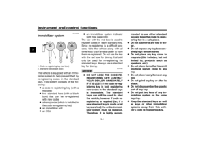 16
16 17
17 18
18 19
19 20
20 21
21 22
22 23
23 24
24 25
25 26
26 27
27 28
28 29
29 30
30 31
31 32
32 33
33 34
34 35
35 36
36 37
37 38
38 39
39 40
40 41
41 42
42 43
43 44
44 45
45 46
46 47
47 48
48 49
49 50
50 51
51 52
52 53
53 54
54 55
55 56
56 57
57 58
58 59
59 60
60 61
61 62
62 63
63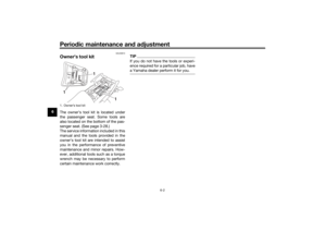 64
64 65
65 66
66 67
67 68
68 69
69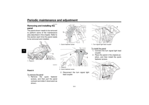 70
70 71
71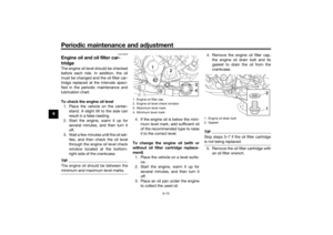 72
72 73
73 74
74 75
75 76
76 77
77 78
78 79
79 80
80 81
81 82
82 83
83 84
84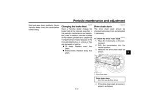 85
85 86
86 87
87 88
88 89
89 90
90 91
91 92
92 93
93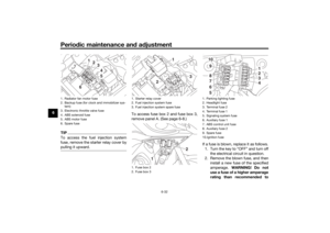 94
94 95
95 96
96 97
97 98
98 99
99 100
100 101
101 102
102 103
103 104
104 105
105 106
106 107
107 108
108 109
109 110
110 111
111 112
112 113
113
