Page 33 of 114

Instrument and control functions
3-18
3
4. If one or both of the standard keys
do not start the engine, take the
vehicle along with all three keys to
a Yamaha dealer to have them re-
registered.
EAU47634
D-mo de ( drive mo de)D-mode is an electronically controlled
engine performance system with three
mode selections (“STD”, “A”, and “B”).
Push the drive mode switch “MODE”
to switch between modes. (See page
3-20 for an explanation of the drive
mode switch.)TIPBefore using D-mode, make sure you
understand its operation along with the
operation of the drive mode switch.Mo de “STD”
Mode “STD” is suitable for various rid-
ing conditions. This mode allows the rider to enjoy
smooth and sporty drivability from the
low-speed range to the high-speed
range.
Mo
de “A”
Mode “A” offers a sportier engine re-
sponse in the low- to mid-speed range
compared to mode “STD”.
Mo de “B”
Mode “B” offers response that is
somewhat less sharp compared to
mode “STD” for riding situations that
require especially sensitive throttle op-
eration.1. Drive mode switch “MODE”
1
U2PPE2E0.book Page 18 Tuesday, June 9, 2015 1:57 PM
Page 34 of 114

Instrument and control functions
3-19
3
EAU1234H
Han dle bar switchesLeft Ri
ght
EAU54201
Dimmer/Pass switch “ / /PASS”
Set this switch to “ ” for the high
beam and to “ ” for the low beam.
To flash the high beam, push the pass
side “PASS” of the switch while the
headlights are on low beam.
EAU12461
Turn si gnal switch “ / ”
To signal a right-hand turn, push this
switch to “ ”. To signal a left-hand
turn, push this switch to “ ”. When
released, the switch returns to the cen- ter position. To cancel the turn signal
lights, push the switch in after it has re-
turned to the center position.
EAU12501
Horn switch “ ”
Press this switch to sound the horn.
EAU54212
Stop/Run/Start switch “ / / ”
To crank the engine with the starter,
set this switch to “ ”, and then push
the switch down towards “ ”. See
page 5-1 for starting instructions prior
to starting the engine.
Set this switch to “ ” to stop the en-
gine in case of an emergency, such as
when the vehicle overturns or when the
throttle cable is stuck.
EAU42342
The engine trouble warning light and
ABS warning light may come on when
the key is turned to “ON” and the start
switch is pushed, but this does not in-
dicate a malfunction.
1. Select switch “ / ”
2. Menu switch “MENU”
3. Dimmer/Pass switch “ / /PASS”
4. Turn signal switch “ / ”
5. Horn switch “ ”
2
1
345
1. Stop/Run/Start switch “ / / ”
2. Drive mode switch “MODE”
3. Hazard switch “ ”
1
23
U2PPE2E0.book Page 19 Tuesday, June 9, 2015 1:57 PM
Page 35 of 114

Instrument and control functions
3-20
3
EAU12735
Hazar d switch “ ”
With the key in the “ON” or “ ” posi-
tion, use this switch to turn on the haz-
ard lights (simultaneous flashing of all
turn signal lights).
The hazard lights are used in case of an
emergency or to warn other drivers
when your vehicle is stopped where it
might be a traffic hazard.NOTICE
ECA10062
Do not use the hazar d lig hts for an
exten ded len gth of time with the en-
g ine not running , otherwise the bat-
tery may d ischarge.
EAU59010
Menu switch “MENU”
This switch is used to perform selec-
tions in the setting mode display of the
multi-function meter unit.
See “Multi-function meter unit” on
page 3-6 for detailed information.
EAU59000
Select switch “ / ”
This switch is used to perform selec-
tions in the information display and
setting mode display of the multi-func-
tion meter unit.
See “Multi-function meter unit” on
page 3-6 for detailed information.
EAU47496
Drive mo de switch “MODE”
WARNING
EWA15341
Do not chan ge the D-mod e while the
vehicle is movin g.Using this switch changes the drive
mode to “STD”, “A”, or “B” in the fol-
lowing order:
STD → A → B → STD
The throttle grip must be completely
closed in order to change the drive mo-
de. (See page 3-18 for an explanation
of each drive mode.)TIP The mode is set to “STD” by de-
fault. The mode resets to “STD”
when the key is turned to “OFF”.
The selected mode is shown on
the drive mode display. (See page
3-9.)
U2PPE2E0.book Page 20 Tuesday, June 9, 2015 1:57 PM
Page 36 of 114

Instrument and control functions
3-21
3
EAU12822
Clutch leverThe clutch lever is located on the left
side of the handlebar. To disengage
the clutch, pull the lever toward the
handlebar grip. To engage the clutch,
release the lever. The lever should be
pulled rapidly and released slowly for
smooth clutch operation.
The clutch lever is equipped with a
clutch switch, which is part of the igni-
tion circuit cut-off system. (See page
3-37.)
EAU12872
Shift pe dalThe shift pedal is located on the left
side of the motorcycle and is used in
combination with the clutch lever when
shifting the gears of the 6-speed con-
stant-mesh transmission equipped on
this motorcycle.
EAU26825
Brake leverThe brake lever is located on the right
side of the handlebar. To apply the
front brake, pull the lever toward the
throttle grip.
The brake lever is equipped with a
brake lever position adjusting dial. To
adjust the distance between the brake
lever and the throttle grip, turn the ad-
justing dial while holding the lever
pushed away from the throttle grip.
Make sure that the appropriate setting
on the adjusting dial is aligned with
the “ ” mark on the brake lever.
1. Clutch lever
1
1. Shift pedal
1
1. Brake lever
2. Distance between brake lever and throttle
grip
3. Brake lever position adjusting dial
4. “ ” mark
2
3
4
1
U2PPE2E0.book Page 21 Tuesday, June 9, 2015 1:57 PM
Page 37 of 114

Instrument and control functions
3-22
3
EAU12944
Brake ped alThe brake pedal is located on the right
side of the motorcycle. To apply the
rear brake, press down on the brake
pedal.
EAU63040
ABSThe Yamaha ABS (Anti-lock Brake
System) features a dual electronic con-
trol system, which acts on the front and
rear brakes independently.
Operate the brakes with ABS as you
would conventional brakes. If the ABS
is activated, a pulsating sensation may
be felt at the brake lever or brake ped-
al. In this situation, continue to apply
the brakes and let the ABS work; do
not “pump” the brakes as this will re-
duce braking effectiveness.
WARNING
EWA16051
Always keep a sufficient d istance
from the vehicle ahead to match the
ri din g speed even with ABS.
The ABS performs best with
lon g b rakin g d istances.
On certain surfaces, such as
rou gh or g ravel roa ds, the b rak-
in g d istance may be lon ger with
the ABS than without.The ABS is monitored by an ECU,
which will revert the system to conven-
tional braking if a malfunction occurs.
TIP The ABS performs a self-diagno-
sis test each time the vehicle first
starts off after the key is turned to
“ON” and the vehicle has traveled
at a speed of 10 km/h (6 mi/h) or
higher. During this test, a “click-
ing” noise can be heard from the
hydraulic control unit, and if the
brake lever or brake pedal is even
slightly applied, a vibration can be
felt at the lever and pedal, but
these do not indicate a malfunc-
tion.
This ABS has a test mode which
allows the owner to experience
the pulsation at the brake lever or
brake pedal when the ABS is op-
erating. However, special tools are
required, so please consult your
Yamaha dealer.NOTICE
ECA20100
Be careful not to d amage the wheel
sensor or wheel sensor rotor; other-
wise, improper performance of the
ABS will result.
1. Brake pedal
1
U2PPE2E0.book Page 22 Tuesday, June 9, 2015 1:57 PM
Page 38 of 114

Instrument and control functions
3-23
3
EAU54271
Traction control systemThe traction control system helps
maintain traction when accelerating on
slippery surfaces, such as unpaved or
wet roads. If sensors detect that the
rear wheel is starting to slip (uncon-
trolled spinning), the traction control
system assists by regulating engine
power as needed until traction is re-
stored. The “TCS” indicator/warning
light flashes to let the rider know that
traction control has engaged.TIPThe rider may also notice slight chang-
es in engine and exhaust sounds when
the traction control system is engaged.
WARNING
EWA15432
The traction control system is not a
su bstitute for rid ing appropriately
for the con ditions. Traction control
cannot prevent loss of traction d ue
to excessive speed when entering
turns, when acceleratin g har d at a
sharp lean an gle, or while b raking,
an d cannot prevent front wheel slip-
pin g. As with any motorcycle, ap- proach surfaces that may
be
slippery with caution an d avoi d es-
pecially slippery surfaces.
When the key is turned to “ON”, the
traction control system automatically
turns on.
The traction control system can be
turned on or off manually only when
the key is in the “ON” position and the
motorcycle is stopped.TIPTurn the traction control system off to
help free the rear wheel if the motorcy-
cle gets stuck in mud, sand, or other
soft surfaces.NOTICE
ECA16801
Use only the specified tires. (See
pa ge 6-17.) Usin g different sized
tires will prevent the traction control
system from controllin g tire rotation
accurately.
1. Front wheel sensor
2. Front wheel sensor rotor
1. Rear wheel sensor
2. Rear wheel sensor rotor
21
12
U2PPE2E0.book Page 23 Tuesday, June 9, 2015 1:57 PM
Page 39 of 114

Instrument and control functions
3-24
3
Turnin
g on/off the traction control
system
WARNING
EWA15441
Be sure to stop the vehicle before
makin g any settin g chan ges to the
traction control system. Chan gin g
settin gs while ri din g can distract the
operator an d increase the risk of an
acci dent.To turn off the traction control system,
push the “TCS” button on the multi-
function meter unit for at least 2 sec-
onds. The “TCS” indicator/warning
light will come on.
To turn on the traction control system,
push the “TCS” button again. The
“TCS” indicator/warning light will go
off. Resettin
g
The traction control system will be dis-
abled in the following conditions: The rear wheel is rotated with the
centerstand down and the key in
the “ON” position.
Either the front wheel or rear wheel
comes off the ground while riding.
Excessive rear wheel spinning.
If the traction control system has been
disabled, both the “TCS” indica-
tor/warning light and the engine trou-
ble warning light come on. To reset the traction control system
Turn the key to “OFF”. Wait at least 1
second, then turn the key back to
“ON”. The “TCS” indicator/warning
light should go off and the system will
be enabled. The engine trouble warn-
ing light should go off after the motor-
cycle reaches at least 20 km/h (12
mi/h). If the “TCS” indicator/warning
light and/or engine trouble warning
light still remain on after resetting, the
motorcycle may still be ridden; howev-
er, have a Yamaha dealer check the
motorcycle as soon as possible.
1. “TCS” button
2. Traction control system indicator/warning
light “TCS”
12
U2PPE2E0.book Page 24 Tuesday, June 9, 2015 1:57 PM
Page 40 of 114

Instrument and control functions
3-25
3
EAU13075
Fuel tank capTo open the fuel tank cap
Open the fuel tank cap lock cover, in-
sert the key into the lock, and then turn
it 1/4 turn clockwise. The lock will be
released and the fuel tank cap can be
opened.
To close the fuel tank cap
1. Push the fuel tank cap into posi- tion with the key inserted in the
lock.
2. Turn the key counterclockwise to the original position, remove it,
and then close the lock cover.
TIPThe fuel tank cap cannot be closed un-
less the key is in the lock. In addition,
the key cannot be removed if the cap is
not properly closed and locked.
WARNING
EWA11092
Make sure that the fuel tank cap is
properly close d after fillin g fuel.
Leakin g fuel is a fire hazar d.
EAU13222
FuelMake sure there is sufficient gasoline in
the tank.
WARNING
EWA10882
Gasoline an d g asoline vapors are
extremely flammab le. To avoid fires
an d explosions an d to re duce the
risk of injury when refuelin g, follow
these instructions.1. Before refueling, turn off the en- gine and be sure that no one is sit-
ting on the vehicle. Never refuel
while smoking, or while in the vi-
cinity of sparks, open flames, or
other sources of ignition such as
the pilot lights of water heaters
and clothes dryers.
2. Do not overfill the fuel tank. When refueling, be sure to insert the
pump nozzle into the fuel tank filler
hole. Stop filling when the fuel
reaches the bottom of the filler
tube. Because fuel expands when
it heats up, heat from the engine or
the sun can cause fuel to spill out
of the fuel tank.
1. Unlock.
2. Fuel tank cap lock cover
2
1
U2PPE2E0.book Page 25 Tuesday, June 9, 2015 1:57 PM
 1
1 2
2 3
3 4
4 5
5 6
6 7
7 8
8 9
9 10
10 11
11 12
12 13
13 14
14 15
15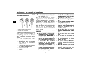 16
16 17
17 18
18 19
19 20
20 21
21 22
22 23
23 24
24 25
25 26
26 27
27 28
28 29
29 30
30 31
31 32
32 33
33 34
34 35
35 36
36 37
37 38
38 39
39 40
40 41
41 42
42 43
43 44
44 45
45 46
46 47
47 48
48 49
49 50
50 51
51 52
52 53
53 54
54 55
55 56
56 57
57 58
58 59
59 60
60 61
61 62
62 63
63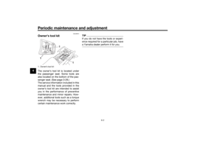 64
64 65
65 66
66 67
67 68
68 69
69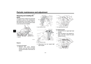 70
70 71
71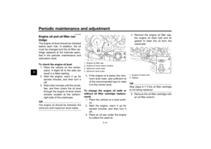 72
72 73
73 74
74 75
75 76
76 77
77 78
78 79
79 80
80 81
81 82
82 83
83 84
84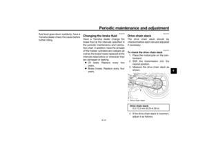 85
85 86
86 87
87 88
88 89
89 90
90 91
91 92
92 93
93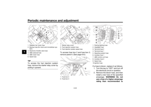 94
94 95
95 96
96 97
97 98
98 99
99 100
100 101
101 102
102 103
103 104
104 105
105 106
106 107
107 108
108 109
109 110
110 111
111 112
112 113
113