Page 73 of 114
Periodic maintenance an d a djustment
6-11
6
TIPAn oil filter wrench is available at a
Yamaha dealer.6. Apply a thin coat of clean engine oil to the O-ring of the new oil filter
cartridge.
TIPMake sure that the O-ring is properly
seated.7. Install the new oil filter cartridgewith an oil filter wrench, and then
tighten it to the specified torque
with a torque wrench. 8. Install the engine oil drain bolt and
its new gasket, and then tighten
the bolt to the specified torque.
9. Refill with the specified amount of the recommended engine oil, and
then install and tighten the oil filler
cap.
1. Oil filter wrench
2. Oil filter cartridge
2
1
1. O-ring
1. Torque wrench
Tightenin g torque:
Oil filter cartridge: 17 Nm (1.7 m·kgf, 12 ft·lbf)
Ti ghtenin g torque:
Engine oil drain bolt:
43 Nm (4.3 m·kgf, 31 ft·lbf)
1
U2PPE2E0.book Page 11 Tuesday, June 9, 2015 1:57 PM
Page 74 of 114

Periodic maintenance an d a djustment
6-12
6
TIPBe sure to wipe off spilled oil on any
parts after the engine and exhaust sys-
tem have cooled down.NOTICE
ECA11621
In or der to prevent clutch slip-
pa ge (since the en gine oil also
lu bricates the clutch), do not
mix any chemical additives. Do
not use oils with a d iesel speci-
fication of “CD” or oils of a hi gh-
er quality than specifie d. In
a ddition, do not use oils la beled
“ENERGY CONSERVING II” or
hi gher.
Make sure that no forei gn mate-
rial enters the crankcase.
10. Start the engine, and then let it idle for several minutes while checking
it for oil leakage. If oil is leaking,
immediately turn the engine off
and check for the cause.TIPAfter the engine is started, the engine
oil level warning light should go off if
the oil level is sufficient.NOTICE
ECA10402
If the oil level warnin g lig ht flickers
or remains on even if the oil level is
correct, immed iately turn the en gine
off an d have a Yamaha d ealer check
the vehicle.11. Turn the engine off, wait a few mi- nutes until the oil settles, and then
check the oil level and correct it if
necessary.
EAU20071
CoolantThe coolant level should be checked
before each ride. In addition, the cool-
ant must be changed at the intervals
specified in the periodic maintenance
and lubrication chart.
EAU40157
To check the coolant level1. Place the vehicle on the center- stand.TIPThe coolant level must be
checked on a cold engine since
the level varies with engine tem-
perature.
Make sure that the vehicle is posi-
tioned straight up when checking
the coolant level. A slight tilt to the
side can result in a false reading.2. Check the coolant level in the
coolant reservoir.TIPThe coolant should be between the mi-
nimum and maximum level marks.
Recommen ded en gine oil:
See page 8-1.
Oil quantity: Oil change:
2.40 L (2.54 US qt, 2.11 Imp.qt)
With oil filter removal: 2.70 L (2.85 US qt, 2.38 Imp.qt)
U2PPE2E0.book Page 12 Tuesday, June 9, 2015 1:57 PM
Page 75 of 114

Periodic maintenance an d a djustment
6-13
6
3. If the coolant is at or below the mi-
nimum level mark, remove the
coolant reservoir cap. WARNING!
Remove only the coolant reser-
voir cap. Never attempt to re-
move the ra diator cap when the
en gine is hot.
[EWA15162]
4. Add coolant or distilled water to
raise the coolant to the maximum
level mark, install the coolant res-
ervoir cap. NOTICE: If coolant is
not availab le, use distille d water
or soft tap water instea d. Do not
use har d water or salt water
since it is harmful to the en gine.
If water has been used instead
of coolant, replace it with cool-
ant as soon as possi ble, other-
wise the coolin g system will not
b e protecte d a gainst frost an d
corrosion. If water has b een
a dd ed to the coolant, have a
Yamaha dealer check the anti-
freeze content of the coolant as soon as possi
ble, otherwise the
effectiveness of the coolant will
b e re duce d.
[ECA10473]
EAU63111
To change the coolant
1. Place the vehicle on the center- stand.
2. Remove panel A. (See page 6-8.)
3. Place a container under the en- gine to collect the used coolant.
4. Remove the radiator cap retaining bolt, radiator cap retainer and ra-
diator cap. WARNING! Never at-
tempt to remove the ra diator
cap when the en gine is hot.
[EWA10382]
1. Coolant reservoir
2. Maximum level mark
3. Minimum level mark
21
3
1. Coolant reservoir cap
1
Coolant reservoir capacity (up to
the maximum level mark):
0.25 L (0.26 US qt, 0.22 Imp.qt)
U2PPE2E0.book Page 13 Tuesday, June 9, 2015 1:57 PM
Page 76 of 114

Periodic maintenance an d a djustment
6-14
6
5. Remove the coolant reservoir cov-
er and coolant reservoir by remov-
ing the bolts and collars. 6. Remove the coolant reservoir cap.
7. Drain the coolant from the coolant
reservoir by turning it upside
down.
8. Install the coolant reservoir and its cover by placing them in the origi-
nal position, and then installing the
collars and bolts.
9. Remove the coolant drain bolt and its gasket to drain the cooling sys-
tem. 10. After the coolant is completely
drained, thoroughly flush the cool-
ing system with clean tap water.
11. Install the coolant drain bolt and its new gasket, and then tighten
the bolt to the specified torque.
12. Pour the specified amount of the recommended coolant into the ra-
diator and reservoir.
1. Radiator cap
2. Radiator cap retaining bolt
3. Radiator cap retainer
1. Bolt
2. Coolant reservoir cover
3. Coolant reservoir
4. Collar
2
1
31
1
2
4
3
4
1. Coolant reservoir cap
1
1. Coolant drain bolt
2. GasketTightenin g torque:
Coolant drain bolt: 10 Nm (1.0 m·kgf, 7.2 ft·lbf)1
2
U2PPE2E0.book Page 14 Tuesday, June 9, 2015 1:57 PM
Page 77 of 114

Periodic maintenance an d a djustment
6-15
6
13. Install the coolant reservoir cap.
14. Install the radiator cap.
15. Start the engine, let it idle for sev-
eral minutes, and then turn it off.
16. Remove the radiator cap to check the coolant level in the radiator. If
necessary, add sufficient coolant
until it reaches the top of the radi-
ator, and then install the radiator
cap, radiator cap retainer and ra-
diator cap retaining bolt.
17. Check the coolant level in the res- ervoir. If necessary, remove the
coolant reservoir cap, add coolant
to the maximum level mark, and
then install the cap. 18. Start the engine, and then check
the vehicle for coolant leakage. If
coolant is leaking, have a Yamaha
dealer check the cooling system.
19. Turn off the engine, and then in- stall the panel.
EAU36765
Air filter elementThe air filter element must be replaced
at the intervals specified in the periodic
maintenance and lubrication chart.
Have a Yamaha dealer replace the air
filter element.
Antifreeze/water mixture ratio:1:1
Recommen ded antifreeze:
High-quality ethylene glycol anti-
freeze containing corrosion inhibi-
tors for aluminum engines
Coolant quantity:
Radiator (including all routes):1.93 L (2.04 US qt, 1.70 Imp.qt)
Coolant reservoir (up to the maxi-
mum level mark): 0.25 L (0.26 US qt, 0.22 Imp.qt)
U2PPE2E0.book Page 15 Tuesday, June 9, 2015 1:57 PM
Page 78 of 114
Periodic maintenance an d a djustment
6-16
6
EAU44735
Checkin g the eng ine idlin g
spee dCheck the engine idling speed and, if
necessary, have it corrected by a
Yamaha dealer.
EAU21385
Checkin g the throttle grip free
playThe throttle grip free play should mea-
sure 3.0–5.0 mm (0.12–0.20 in) at the
inner edge of the throttle grip. Periodi-
cally check the throttle grip free play
and, if necessary, have a Yamaha deal-
er adjust it.
EAU21402
Valve clearanceThe valve clearance changes with use,
resulting in improper air-fuel mixture
and/or engine noise. To prevent this
from occurring, the valve clearance
must be adjusted by a Yamaha dealer
at the intervals specified in the periodic
maintenance and lubrication chart.
En gine i dlin g spee d:
1100–1300 r/min
1. Throttle grip free play
1
U2PPE2E0.book Page 16 Tuesday, June 9, 2015 1:57 PM
Page 79 of 114

Periodic maintenance an d a djustment
6-17
6
EAU64270
TiresTires are the only contact between the
vehicle and the road. Safety in all con-
ditions of riding depends on a relatively
small area of road contact. Therefore, it
is essential to maintain the tires in good
condition at all times and replace them
at the appropriate time with the speci-
fied tires.
Tire air pressure
The tire air pressure should be
checked and, if necessary, adjusted
before each ride.
WARNING
EWA10504
Operation of this vehicle with im-
proper tire pressure may cause se-
vere injury or d eath from loss of
control. The tire air pressure must b e
checked and a djuste d on col d
tires (i.e., when the temperature
of the tires equals the am bient
temperature).
The tire air pressure must b e
a d juste d in accor dance with the
ri din g speed and with the total wei
ght of ri der, passen ger, car-
g o, an d accessories approve d
for this mo del.
WARNING
EWA10512
Never overloa d your vehicle. Opera-
tion of an overloa ded vehicle coul d
cause an acci dent.
Tire inspection
The tires must be checked before each
ride. If the center tread depth reaches
the specified limit, if the tire has a nail
or glass fragments in it, or if the side-
wall is cracked, have a Yamaha dealer
replace the tire immediately.TIPThe tire tread depth limits may differ
from country to country. Always com-
ply with the local regulations.
Tire air pressure (measure d on col d
tires): Up to 90 kg (198 lb) loa d:
Front:
250 kPa (2.50 kgf/cm², 36 psi)
Rear: 290 kPa (2.90 kgf/cm², 42 psi)
90 k g (198 l b) to maximum load :
Front: 250 kPa (2.50 kgf/cm², 36 psi)
Rear: 290 kPa (2.90 kgf/cm², 42 psi)
Maximum loa d*:
180 kg (397 lb)
* Total weight of rider, passenger, car- go and accessories
1. Tire sidewall
2. Tire tread depth
Minimum tire trea d d epth (front an d
rear): 1.6 mm (0.06 in)
U2PPE2E0.book Page 17 Tuesday, June 9, 2015 1:57 PM
Page 80 of 114

Periodic maintenance an d a djustment
6-18
6
WARNING
EWA10472
Have a Yamaha dealer replace
excessively worn tires. Besi des
b ein g ille gal, operatin g the vehi-
cle with excessively worn tires
d ecreases ri din g sta bility an d
can lead to loss of control.
The replacement of all wheel
and b rake-relate d parts, inclu d-
in g the tires, shoul d b e left to a
Yamaha dealer, who has the
necessary professional knowl-
e dge an d experience to do so.
Ride at mo derate speed s after
chan gin g a tire since the tire
surface must first be “ broken
in” for it to develop its optimal
characteristics.
Tire information
This model is equipped with tubeless
tires and tire air valves.
Tires age, even if they have not been
used or have only been used occasion-
ally. Cracking of the tread and sidewall
rubber, sometimes accompanied by
carcass deformation, is an evidence of
ageing. Old and aged tires shall be
checked by tire specialists to ascertain
their suitability for further use.
WARNING
EWA10902
The front an d rear tires shoul d
b e of the same make an d d e-
si gn, otherwise the han dlin g characteristics of the motorcy-
cle may
be different, which
coul d lea d to an acci dent.
Always make sure that the valve
caps are securely installe d to
prevent air pressure leaka ge.
Use only the tire valves an d
valve cores liste d below to
avoi d tire d eflation during a ride.
After extensive tests, only the tires list-
ed below have been approved for this
model by Yamaha.
1. Tire air valve
2. Tire air valve core
3. Tire air valve cap with seal
Front tire:
Size:120/70ZR17 M/C (58W)
Manufacturer/model: DUNLOP/D222F
Rear tire:
Size:180/55ZR17 M/C (73W)
Manufacturer/model:
DUNLOP/D222
FRONT an d REAR:
Tire air valve:
TR412
Valve core: #9100 (original)
U2PPE2E0.book Page 18 Tuesday, June 9, 2015 1:57 PM
 1
1 2
2 3
3 4
4 5
5 6
6 7
7 8
8 9
9 10
10 11
11 12
12 13
13 14
14 15
15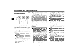 16
16 17
17 18
18 19
19 20
20 21
21 22
22 23
23 24
24 25
25 26
26 27
27 28
28 29
29 30
30 31
31 32
32 33
33 34
34 35
35 36
36 37
37 38
38 39
39 40
40 41
41 42
42 43
43 44
44 45
45 46
46 47
47 48
48 49
49 50
50 51
51 52
52 53
53 54
54 55
55 56
56 57
57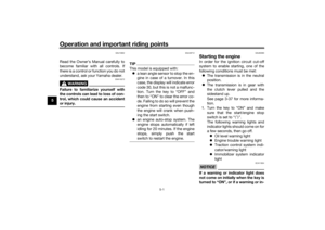 58
58 59
59 60
60 61
61 62
62 63
63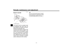 64
64 65
65 66
66 67
67 68
68 69
69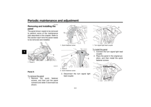 70
70 71
71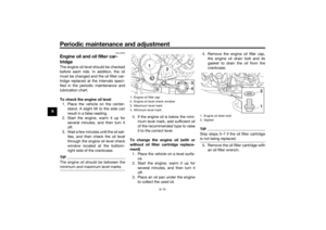 72
72 73
73 74
74 75
75 76
76 77
77 78
78 79
79 80
80 81
81 82
82 83
83 84
84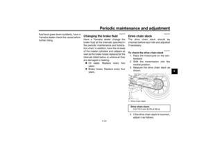 85
85 86
86 87
87 88
88 89
89 90
90 91
91 92
92 93
93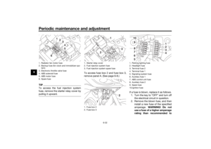 94
94 95
95 96
96 97
97 98
98 99
99 100
100 101
101 102
102 103
103 104
104 105
105 106
106 107
107 108
108 109
109 110
110 111
111 112
112 113
113
