2016 NISSAN NOTE clutch
[x] Cancel search: clutchPage 2062 of 3641
SERVICE DATA AND SPECIFICATIONS (SDS)HA-37
< SERVICE DATA AND SPECIFICATIONS (SDS)
C
DE
F
G H
J
K L
M A
B
HA
N
O P
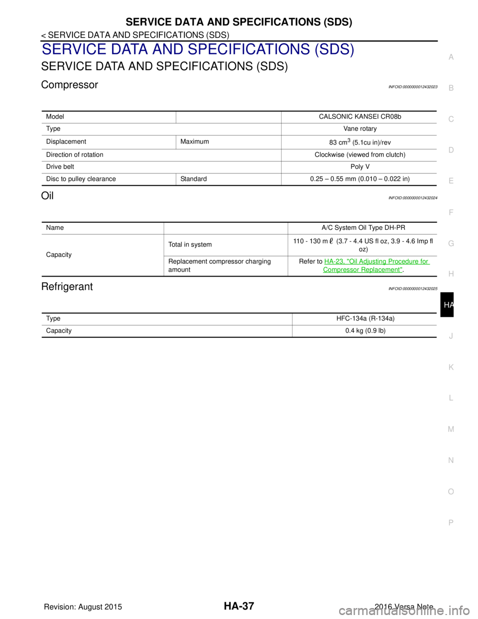
SERVICE DATA AND SPECIFICATIONS (SDS)
SERVICE DATA AND SPECIFICATIONS (SDS)
CompressorINFOID:0000000012432023
OilINFOID:0000000012432024
RefrigerantINFOID:0000000012432025
Model CALSONIC KANSEI CR08b
Ty p e Vane rotary
Displacement Maximum 83 cm
3 (5.1cu in)/rev
Direction of rotation Clockwise (viewed from clutch)
Drive belt Poly V
Disc to pulley clearance Standard0.25 – 0.55 mm (0.010 – 0.022 in)
Name A/C System Oil Type DH-PR
Capacity Total in system
110 - 130 m (3.7 - 4.4 US fl oz, 3.9 - 4.6 Imp fl
oz)
Replacement compressor charging
amount Refer to
HA-23, "
Oil Adjusting Procedure for
Compressor Replacement".
Ty p e HFC-134a (R-134a)
Capacity 0.4 kg (0.9 lb)
Revision: August 20152016 Versa Note
cardiagn.com
Page 2077 of 3641
SQUEAK AND RATTLE TROUBLE DIAGNOSESIP-9
< SYMPTOM DIAGNOSIS >
C
DE
F
G H
I
K L
M A
B
IP
N
O P
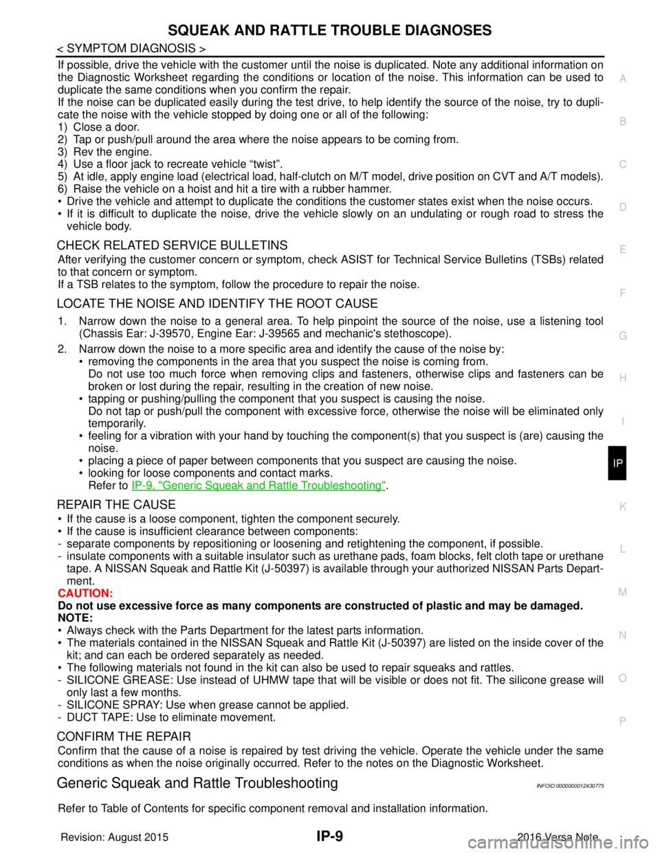
If possible, drive the vehicle with the customer until the noise is duplicated. Note any additional information on
the Diagnostic Worksheet regarding the conditions or lo cation of the noise. This information can be used to
duplicate the same conditions when you confirm the repair.
If the noise can be duplicated easily during the test drive, to help identify the source of the noise, try to dupli-
cate the noise with the vehicle stopped by doing one or all of the following:
1) Close a door.
2) Tap or push/pull around the area where the noise appears to be coming from.
3) Rev the engine.
4) Use a floor jack to recreate vehicle “twist”.
5) At idle, apply engine load (electrical load, half-clutch on M/T model, drive position on CVT and A/T models).
6) Raise the vehicle on a hoist and hit a tire with a rubber hammer.
• Drive the vehicle and attempt to duplicate the conditions the customer states exist when the noise occurs.
• If it is difficult to duplicate the noise, drive the vehicle slowly on an undulating or rough road to stress the
vehicle body.
CHECK RELATED SERVICE BULLETINS
After verifying the customer concern or symptom, check ASIST for Technical Service Bulletins (TSBs) related
to that concern or symptom.
If a TSB relates to the symptom, follow the procedure to repair the noise.
LOCATE THE NOISE AND IDENTIFY THE ROOT CAUSE
1. Narrow down the noise to a general area. To help pinpoint the source of the noise, use a listening tool (Chassis Ear: J-39570, Engine Ear: J-39565 and mechanic's stethoscope).
2. Narrow down the noise to a more specific area and identify the cause of the noise by: • removing the components in the area that you suspect the noise is coming from.Do not use too much force when removing clips and fasteners, otherwise clips and fasteners can be
broken or lost during the repair, resulting in the creation of new noise.
• tapping or pushing/pulling the component that you suspect is causing the noise.
Do not tap or push/pull the component with excessive force, otherwise the noise will be eliminated only
temporarily.
• feeling for a vibration with your hand by touching the component(s) that you suspect is (are) causing the
noise.
• placing a piece of paper between components that you suspect are causing the noise.
• looking for loose components and contact marks. Refer to IP-9, "
Generic Squeak and Rattle Troubleshooting".
REPAIR THE CAUSE
• If the cause is a loose component, tighten the component securely.
• If the cause is insufficient clearance between components:
- separate components by repositioning or loos ening and retightening the component, if possible.
- insulate components with a suitable insulator such as urethane pads, foam blocks, felt cloth tape or urethane tape. A NISSAN Squeak and Rattle Kit (J-50397) is available through your authorized NISSAN Parts Depart-
ment.
CAUTION:
Do not use excessive force as many components are constructed of plastic and may be damaged.
NOTE:
• Always check with the Parts Department for the latest parts information.
• The materials contained in the NISSAN Squeak and Rattle Kit (J-50397) are listed on the inside cover of the
kit; and can each be ordered separately as needed.
• The following materials not found in the kit can also be used to repair squeaks and rattles.
- SILICONE GREASE: Use instead of UHMW tape that will be visible or does not fit. The silicone grease will
only last a few months.
- SILICONE SPRAY: Use when grease cannot be applied.
- DUCT TAPE: Use to eliminate movement.
CONFIRM THE REPAIR
Confirm that the cause of a noise is repaired by test driving the vehicle. Operate the vehicle under the same
conditions as when the noise originally occurred. Refer to the notes on the Diagnostic Worksheet.
Generic Squeak and Rattle TroubleshootingINFOID:0000000012430775
Refer to Table of Contents for specific component removal and installation information.
Revision: August 2015 2016 Versa Note
cardiagn.com
Page 2106 of 3641
INL-12
< SYSTEM DESCRIPTION >
DIAGNOSIS SYSTEM (BCM) (WITH INTELLIGENT KEY SYSTEM)
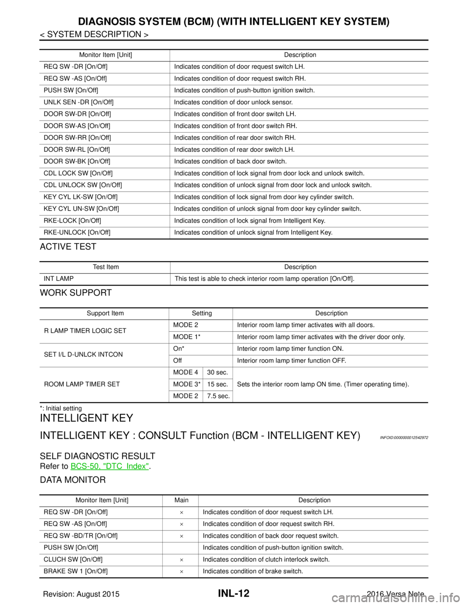
ACTIVE TEST
WORK SUPPORT
*: Initial setting
INTELLIGENT KEY
INTELLIGENT KEY : CONSULT Function (BCM - INTELLIGENT KEY)INFOID:0000000012542972
SELF DIAGNOSTIC RESULT
Refer to BCS-50, "DTCIndex".
DATA MONITOR
Monitor Item [Unit] Description
REQ SW -DR [On/Off] Indicates condition of door request switch LH.
REQ SW -AS [On/Off] Indicates condition of door request switch RH.
PUSH SW [On/Off] Indicates condition of push-button ignition switch.
UNLK SEN -DR [On/Off] Indicates condition of door unlock sensor.
DOOR SW-DR [On/Off] Indicates condition of front door switch LH.
DOOR SW-AS [On/Off] Indicates condition of front door switch RH.
DOOR SW-RR [On/Off] Indicates condition of rear door switch RH.
DOOR SW-RL [On/Off] Indicates condition of rear door switch LH.
DOOR SW-BK [On/Off] Indicates condition of back door switch.
CDL LOCK SW [On/Off] Indicates condition of lock signal from door lock and unlock switch.
CDL UNLOCK SW [On/Off] Indicates condition of unlock signal from door lock and unlock switch.
KEY CYL LK-SW [On/Off] Indicates condition of lock signal from door key cylinder switch.
KEY CYL UN-SW [On/Off] Indicates condition of unlock signal from door key cylinder switch.
RKE-LOCK [On/Off] Indicates condition of lock signal from Intelligent Key.
RKE-UNLOCK [On/Off] Indicates condition of unlock signal from Intelligent Key.
Te s t I t e m D e s c r i p t i o n
INT LAMP This test is able to check interior room lamp operation [On/Off].
Support ItemSetting Description
R LAMP TIMER LOGIC SET MODE 2
Interior room lamp timer activates with all doors.
MODE 1* Interior room lamp timer activates with the driver door only.
SET I/L D-UNLCK INTCON On*
Interior room lamp timer function ON.
Off Interior room lamp timer function OFF.
ROOM LAMP TIMER SET MODE 4 30 sec.
Sets the interior room lamp ON time. (Timer operating time).
MODE 3* 15 sec.
MODE 2 7.5 sec.
Monitor Item [Unit] Main Description
REQ SW -DR [On/Off] ×Indicates condition of door request switch LH.
REQ SW -AS [On/Off] ×Indicates condition of door request switch RH.
REQ SW -BD/TR [On/Off] ×Indicates condition of back door request switch.
PUSH SW [On/Off] Indicates condition of push-button ignition switch.
CLUCH SW [On/Off] ×Indicates condition of clutch interlock switch.
BRAKE SW 1 [On/Off] ×Indicates condition of brake switch.
Revision: August 2015 2016 Versa Note
cardiagn.com
Page 2161 of 3641
INT-10
< SYMPTOM DIAGNOSIS >
SQUEAK AND RATTLE TROUBLE DIAGNOSES
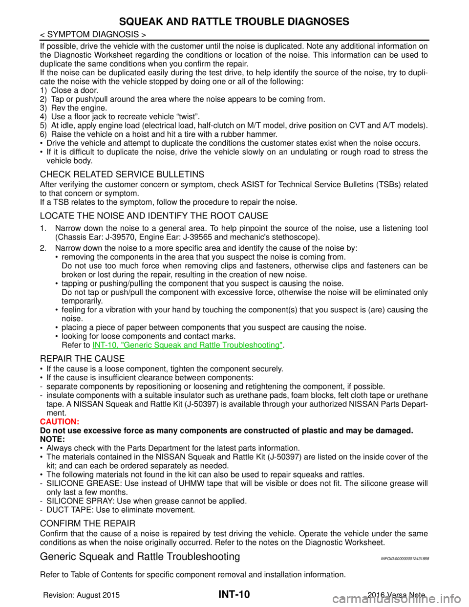
If possible, drive the vehicle with the customer until the noise is duplicated. Note any additional information on
the Diagnostic Worksheet regarding the conditions or lo cation of the noise. This information can be used to
duplicate the same conditions when you confirm the repair.
If the noise can be duplicated easily during the test drive, to help identify the source of the noise, try to dupli-
cate the noise with the vehicle stopped by doing one or all of the following:
1) Close a door.
2) Tap or push/pull around the area where the noise appears to be coming from.
3) Rev the engine.
4) Use a floor jack to recreate vehicle “twist”.
5) At idle, apply engine load (electrical load, half-clutch on M/T model, drive position on CVT and A/T models).
6) Raise the vehicle on a hoist and hit a tire with a rubber hammer.
• Drive the vehicle and attempt to duplicate the conditions the customer states exist when the noise occurs.
• If it is difficult to duplicate the noise, drive the v ehicle slowly on an undulating or rough road to stress the
vehicle body.
CHECK RELATED SERVICE BULLETINS
After verifying the customer concern or symptom, chec k ASIST for Technical Service Bulletins (TSBs) related
to that concern or symptom.
If a TSB relates to the symptom, follo w the procedure to repair the noise.
LOCATE THE NOISE AND IDENTIFY THE ROOT CAUSE
1. Narrow down the noise to a general area. To help pi npoint the source of the noise, use a listening tool
(Chassis Ear: J-39570, Engine Ear: J-39565 and mechanic's stethoscope).
2. Narrow down the noise to a more specific area and identify the cause of the noise by: • removing the components in the area that you suspect the noise is coming from.Do not use too much force when removing clips and fasteners, otherwise clips and fasteners can be
broken or lost during the repair, resulting in the creation of new noise.
• tapping or pushing/pulling the component that you suspect is causing the noise. Do not tap or push/pull the component with excessive force, otherwise the noise will be eliminated only
temporarily.
• feeling for a vibration with your hand by touching the component(s) that you suspec t is (are) causing the
noise.
• placing a piece of paper between components that you suspect are causing the noise.
• looking for loose components and contact marks.
Refer to INT-10, "
Generic Squeak and Rattle Troubleshooting".
REPAIR THE CAUSE
• If the cause is a loose component, tighten the component securely.
• If the cause is insufficient clearance between components:
- separate components by repositioning or loos ening and retightening the component, if possible.
- insulate components with a suitable insulator such as urethane pads, foam blocks, felt cloth tape or urethane tape. A NISSAN Squeak and Rattle Kit (J-50397) is av ailable through your authorized NISSAN Parts Depart-
ment.
CAUTION:
Do not use excessive force as many components are constructed of plastic and may be damaged.
NOTE:
• Always check with the Parts Department for the latest parts information.
• The materials contained in the NISSAN Squeak and Rattle Kit (J-50397) are listed on the inside cover of the
kit; and can each be ordered separately as needed.
• The following materials not found in the kit can also be used to repair squeaks and rattles.
- SILICONE GREASE: Use instead of UHMW tape that will be visible or does not fit. The silicone grease will only last a few months.
- SILICONE SPRAY: Use when grease cannot be applied.
- DUCT TAPE: Use to eliminate movement.
CONFIRM THE REPAIR
Confirm that the cause of a noise is repaired by test driving the vehicle. Operate the vehicle under the same
conditions as when the noise originally occurred. Refer to the notes on the Diagnostic Worksheet.
Generic Squeak and Rattle TroubleshootingINFOID:0000000012431858
Refer to Table of Contents for specific component removal and installation information.
Revision: August 2015 2016 Versa Note
cardiagn.com
Page 2316 of 3641

MA-1
MAINTENANCE
C
DE
F
G H
I
J
K L
M B
MA
SECTION MA
N
O A
CONTENTS
MAINTENANCE
PRECAUTION .......
........................................3
PRECAUTIONS .............................................. .....3
Precaution for Supplemental Restraint System
(SRS) "AIR BAG" and "SEAT BELT PRE-TEN-
SIONER" ............................................................. ......
3
PREPARATION ............................................4
PREPARATION .............................................. .....4
Special Service Tool ........................................... ......4
Commercial Service Tool ..........................................4
PERIODIC MAINTENANCE ..........................5
GENERAL MAINTE NANCE ........................... .....5
Explanation of General Maintenance .................. ......5
PERIODIC MAINTENANCE ................................7
Introduction of Periodic Maintenance .................. ......7
RECOMMENDED FLUIDS AND LUBRI-
CANTS ................................................................
11
Fluids and Lubricants .......................................... ....11
Engine Oil Recommendation ..................................12
Anti-Freeze Coolant Mixture Ratio ..........................12
ENGINE MAINTENANCE ...................................13
DRIVE BELT .......................................................... ....13
DRIVE BELT : Exploded View ................................13
DRIVE BELT : Removal and Installation .................13
DRIVE BELT : Inspection .................................... ....14
DRIVE BELT : Adjustment ......................................14
ENGINE COOLANT ............................................... ....15
ENGINE COOLANT : Inspection .............................15
ENGINE COOLANT : Draining Engine Coolant ......16
ENGINE COOLANT : Refilling ................................16
ENGINE COOLANT : Flushing Cooling System .....18
FUEL LINES .......................................................... ....18
FUEL LINES : Inspection ........................................18
AIR CLEANER FILTER ......................................... ....18
AIR CLEANER FILTER : Exploded View ................19
AIR CLEANER FILTER : Removal and Installation
....
19
ENGINE OIL ........................................................... ....20
ENGINE OIL : Inspection .........................................20
ENGINE OIL : Draining ............................................21
ENGINE OIL : Refilling ............................................21
OIL FILTER ............................................................ ....22
OIL FILTER : Removal and Installation ...................22
SPARK PLUG ........................................................ ....22
SPARK PLUG : Exploded View ...............................23
SPARK PLUG : Removal and Installation ...............23
EVAP VAPOR LINES ............................................ ....25
EVAP VAPOR LINES : Inspection ...........................25
CHASSIS AND BODY MAINTENANCE ...........26
EXHAUST SYSTEM . ..................................................26
EXHAUST SYSTEM : Inspec tion ............................26
CVT FLUID ............................................................. ....26
CVT FLUID : Inspection ...........................................26
CVT FLUID : Replacement ......................................26
CVT FLUID : Adjustment .........................................28
CLUTCH FLUID ..................................................... ....29
CLUTCH FLUID : Inspection ...................................29
CLUTCH FLUID : Draining ......................................29
CLUTCH FLUID : Refilling .......................................30
GEAR OIL .............................................................. ....31
GEAR OIL : Inspection ............................................31
GEAR OIL : Draining ...............................................31
GEAR OIL : Refilling ................................................32
WHEELS ................................................................ ....32
WHEELS : Inspection ..............................................32
WHEELS : Adjustment ............................................32
Revision: August 2015 2016 Versa Note
cardiagn.com
Page 2321 of 3641
MA-6
< PERIODIC MAINTENANCE >
GENERAL MAINTENANCE
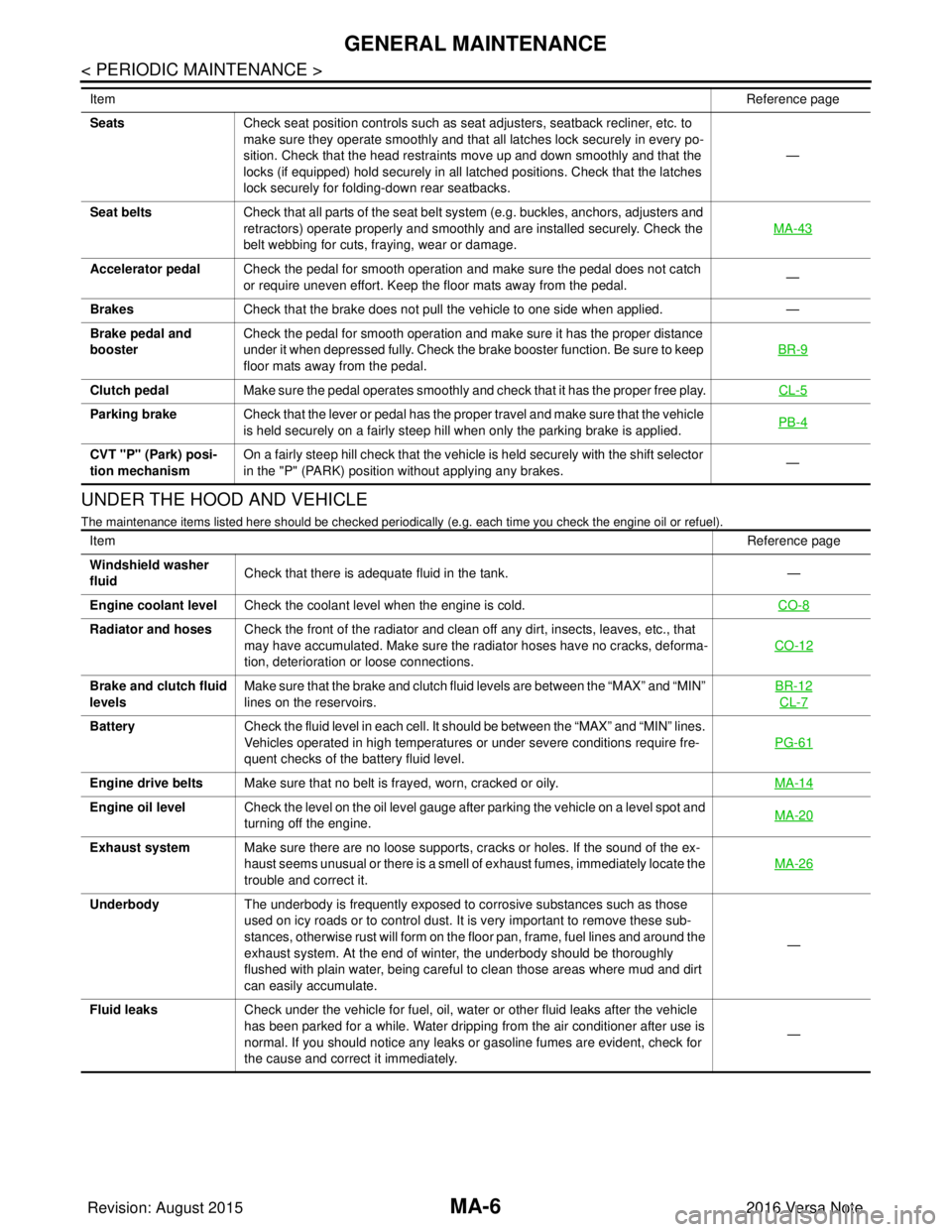
UNDER THE HOOD AND VEHICLE
The maintenance items listed here should be checked periodically (e.g. each time you check the engine oil or refuel).
SeatsCheck seat position controls such as seat adjusters, seatback recliner, etc. to
make sure they operate smoothly and that all latches lock securely in every po-
sition. Check that the head restraints move up and down smoothly and that the
locks (if equipped) hold securely in all latched positions. Check that the latches
lock securely for folding-down rear seatbacks. —
Seat belts Check that all parts of the seat belt system (e.g. buckles, anchors, adjusters and
retractors) operate properly and smoothly and are installed securely. Check the
belt webbing for cuts, fraying, wear or damage. MA-43
Accelerator pedal
Check the pedal for smooth operation and make sure the pedal does not catch
or require uneven effort. Keep the floor mats away from the pedal. —
Brakes Check that the brake does not pull the vehicle to one side when applied. —
Brake pedal and
booster Check the pedal for smooth operation and make sure it has the proper distance
under it when depressed fully. Check the brake booster function. Be sure to keep
floor mats away from the pedal. BR-9
Clutch pedal
Make sure the pedal operates smoothly and check that it has the proper free play. CL-5
Parking brakeCheck that the lever or pedal has the proper travel and make sure that the vehicle
is held securely on a fairly steep hill when only the parking brake is applied. PB-4
CVT "P" (Park) posi-
tion mechanismOn a fairly steep hill check that the vehicle is held securely with the shift selector
in the "P" (PARK) position without applying any brakes.
—
Item
Reference page
Item Reference page
Windshield washer
fluid Check that there is adequate fluid in the tank.
—
Engine coolant level Check the coolant level when the engine is cold. CO-8
Radiator and hosesCheck the front of the radiator and clean off any dirt, insects, leaves, etc., that
may have accumulated. Make sure the radiator hoses have no cracks, deforma-
tion, deterioration or loose connections. CO-12
Brake and clutch fluid
levelsMake sure that the brake and clutch fluid levels are between the “MAX” and “MIN”
lines on the reservoirs. BR-12
CL-7
Battery
Check the fluid level in each cell. It should be between the “MAX” and “MIN” lines.
Vehicles operated in high temperatures or under severe conditions require fre-
quent checks of the battery fluid level. PG-61
Engine drive belts
Make sure that no belt is frayed, worn, cracked or oily. MA-14
Engine oil levelCheck the level on the oil level gauge after parking the vehicle on a level spot and
turning off the engine. MA-20
Exhaust system
Make sure there are no loose supports, cracks or holes. If the sound of the ex-
haust seems unusual or there is a smell of exhaust fumes, immediately locate the
trouble and correct it. MA-26
Underbody
The underbody is frequently exposed to corrosive substances such as those
used on icy roads or to control dust. It is very important to remove these sub-
stances, otherwise rust will form on the floor pan, frame, fuel lines and around the
exhaust system. At the end of winter, the underbody should be thoroughly
flushed with plain water, being careful to clean those areas where mud and dirt
can easily accumulate. —
Fluid leaks Check under the vehicle for fuel, oil, water or other fluid leaks after the vehicle
has been parked for a while. Water dripping from the air conditioner after use is
normal. If you should notice any leaks or gasoline fumes are evident, check for
the cause and correct it immediately. —
Revision: August 2015
2016 Versa Note
cardiagn.com
Page 2326 of 3641
RECOMMENDED FLUIDS AND LUBRICANTSMA-11
< PERIODIC MAINTENANCE >
C
DE
F
G H
I
J
K L
M B
MA
N
O A
RECOMMENDED FLUIDS AND LUBRICANTS
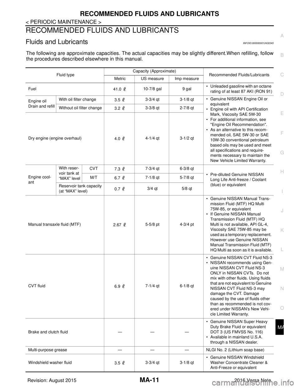
Fluids and LubricantsINFOID:0000000012432245
The following are approximate capacities. The actual capa
cities may be slightly different.When refilling, follow
the procedures described elsewhere in this manual.
Fluid type Capacity (Approximate)
Recommended Fluids/Lubricants
Metric US measure Imp measure
Fuel 41.0 10-7/8 gal
9 gal• Unleaded gasoline with an octane
rating of at least 87 AKI (RON 91)
Engine oil
Drain and refill With oil filter change
3.5 3-3/4 qt 3-1/8 qt
• Genuine NISSAN Engine Oil or
equivalent
• Engine oil with API Certification
Mark, Viscosity SAE 5W-30
• For additional information, see "Engine Oil Recommendation".
• As an alternative to this recom-
mended oil, SAE 5W-30 or SAE
10W-30 conventional petroleum
based oils may be used and meet
all specifications and require-
ments necessary to maintain the
New Vehicle Limited Warranty.
Without oil filter change
3.2 3-3/8 qt 2-7/8 qt
Dry engine (engine overhaul) 4.0 4-1/4 qt 3-1/2 qt
Engine cool-
ant With reser-
voir tank at
“MAX” level
CVT
7.3 7-3/4 qt 6-3/8 qt
• Pre-diluted Genuine NISSAN Long Life Anti-freeze / Coolant
(blue) or equivalent
M/T
6.7 7-1/8 qt 5-7/8 qt
Reservoir tank capacity
(at “MAX” level) 0.7
3/4 qt
5/8 qt
Manual transaxle fluid (MTF) 2.67 5-5/8 pt 4-3/4 pt • Genuine NISSAN
Manual Trans-
mission Fluid (MTF) HQ Multi
75W-85, or equivalent
• If Genuine NISSAN Manual
Transmission Fluid (MTF) HQ
Multi is not available, API GL-4,
Viscosity SAE 75W-85 may be
used as a temporary replacement.
However use Genuine NISSAN
Manual Transmission Fluid (MTF)
HQ Multi as soon as it is available.
CVT fluid 6.9 7-1/4 qt 6-1/8 qt • Genuine NISSAN CVT Fluid NS-3
• NISSAN recommends using Gen-
uine NISSAN CVT Fluid NS-3
ONLY in NISSAN CVTs. Do not
mix with other fluids. Using fluids
that are not equivalent to Genuine
NISSAN CVT Fluid NS-3 may
damage the CVT. Damage
caused by the use of fluids other
than as recommended is not cov-
ered under NISSAN's New Vehi-
cle Limited Warranty.
Brake and clutch fluid —— —• Genuine NISSAN Super Heavy
Duty Brake Fluid or equivalent
DOT 3 (US FMVSS No. 116)
• Available in mainland U.S.A.
through a NISSAN dealer.
Multi-purpose grease —— — NLGI No. 2 (Lithium soap base)
Windshield washer fluid 3.5 3-3/4 qt 3-1/8 qt • Genuine NISSAN Windshield
Washer Concentrate Cleaner &
Anti-Freeze or equivalent
Revision: August 2015 2016 Versa Note
cardiagn.com
Page 2344 of 3641
CHASSIS AND BODY MAINTENANCEMA-29
< PERIODIC MAINTENANCE >
C
DE
F
G H
I
J
K L
M B
MA
N
O A
CLUTCH FLUID
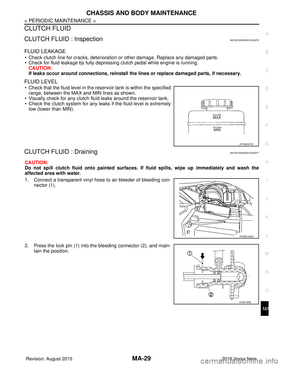
CLUTCH FLUID : InspectionINFOID:0000000012432270
FLUID LEAKAGE
• Check clutch line for cracks, deterioration or other damage. Replace any damaged parts.
• Check for fluid leakage by fully depressing clutch pedal while engine is running.
CAUTION:
If leaks occur around connections, reinstall th e lines or replace damaged parts, if necessary.
FLUID LEVEL
• Check that the fluid level in the reservoir tank is within the specified
range, between the MAX and MIN lines as shown.
• Visually check for any clutch fluid leaks around the reservoir tank.
• Check the clutch system for any leaks if the fluid level is extremely low (lower than MIN).
CLUTCH FLUID : DrainingINFOID:0000000012432271
CAUTION:
Do not spill clutch flui d onto painted surfaces. If fluid spil ls, wipe up immediately and wash the
affected area with water.
1. Connect a transparent vinyl hose to air bleeder of bleeding con- nector (1).
2. Press the lock pin (1) into the bleeding connector (2), and main- tain the position.
JPFIA0007ZZ
JPDIB0144ZZ
PCIB1495E
Revision: August 2015 2016 Versa Note
cardiagn.com