2016 NISSAN NOTE clutch
[x] Cancel search: clutchPage 2015 of 3641
![NISSAN NOTE 2016 Service Repair Manual MANUAL AIR CONDITIONING SYSTEMHAC-47
< SYMPTOM DIAGNOSIS > [MANUAL AIR CONDITIONING]
C
D
E
F
G H
J
K L
M A
B
HAC
N
O P
SYMPTOM DIAGNOSIS
MANUAL AIR CONDITIONING SYSTEM
Symptom TableINFOID:000000001243 NISSAN NOTE 2016 Service Repair Manual MANUAL AIR CONDITIONING SYSTEMHAC-47
< SYMPTOM DIAGNOSIS > [MANUAL AIR CONDITIONING]
C
D
E
F
G H
J
K L
M A
B
HAC
N
O P
SYMPTOM DIAGNOSIS
MANUAL AIR CONDITIONING SYSTEM
Symptom TableINFOID:000000001243](/manual-img/5/57363/w960_57363-2014.png)
MANUAL AIR CONDITIONING SYSTEMHAC-47
< SYMPTOM DIAGNOSIS > [MANUAL AIR CONDITIONING]
C
D
E
F
G H
J
K L
M A
B
HAC
N
O P
SYMPTOM DIAGNOSIS
MANUAL AIR CONDITIONING SYSTEM
Symptom TableINFOID:0000000012430749
SYMPTOM TABLE
Symptom Reference Page
A/C system does not come on. Go to Trouble Diagnosis Procedure for A/C System. HAC-30
A/C system cannot be controlled.Go to Self-diagnosis Function. HAC-28
Air outlet does not change.Go to Adjustment Procedure for Mode Door. HAC-57
Discharge air temperature does not change. Go to Adjustment Procedure for Air Mix Door. HAC-57
Intake door does not change.Go to Adjustment Procedure for Intake Door. HAC-56
Front blower motor operation is malfunction-
ing.Go to Trouble Diagnosis Procedure for Front Blower Motor.
HAC-41
Magnet clutch does not engage.Go to Trouble Diagnosis Procedure for Magnet Clutch. HAC-45
Insufficient cooling.Go to Trouble Diagnosis Procedure for Insufficient Cooling. HAC-48
Insufficient heating.Go to Trouble Diagnosis Procedure for Insufficient Heating. HAC-49
Noise.Go to Trouble Diagnosis Procedure for Noise. HA-17
A/C switch LED does not illuminate. Go to Trouble Diagnosis Procedure for A/C System. HAC-39
Both high- and low-pressure sides are too
high.Go to Trouble Diagnosis Procedure for Abnormal Pressure.
HA-15
High-pressure side is too high and low pres-
sure side is too low.Go to Trouble Diagnosis Procedure for Abnormal Pressure.
HA-15
High-pressure side is too low and low-pres-
sure side is too high.Go to Trouble Diagnosis Procedure for Abnormal Pressure.
HA-15
Both high- and low-pressure side sometimes
become negative.Go to Trouble Diagnosis Procedure for Abnormal Pressure.
HA-15
Low-pressure side sometimes becomes neg-
ative.Go to Trouble Diagnosis Procedure for Abnormal Pressure.
HA-15
Low-pressure side becomes negative. Go to Trouble Diagnosis Procedure for Abnormal Pressure. HA-15
Revision: August 20152016 Versa Note
cardiagn.com
Page 2016 of 3641
![NISSAN NOTE 2016 Service Repair Manual HAC-48
< SYMPTOM DIAGNOSIS >[MANUAL AIR CONDITIONING]
INSUFFICIENT COOLING
INSUFFICIENT COOLING
DescriptionINFOID:0000000012430750
Symptom
• Insufficient cooling
• No cool air comes out. (Air flow NISSAN NOTE 2016 Service Repair Manual HAC-48
< SYMPTOM DIAGNOSIS >[MANUAL AIR CONDITIONING]
INSUFFICIENT COOLING
INSUFFICIENT COOLING
DescriptionINFOID:0000000012430750
Symptom
• Insufficient cooling
• No cool air comes out. (Air flow](/manual-img/5/57363/w960_57363-2015.png)
HAC-48
< SYMPTOM DIAGNOSIS >[MANUAL AIR CONDITIONING]
INSUFFICIENT COOLING
INSUFFICIENT COOLING
DescriptionINFOID:0000000012430750
Symptom
• Insufficient cooling
• No cool air comes out. (Air flow volume is normal.)
Diagnosis ProcedureINFOID:0000000012430751
NOTE:
Perform self-diagnosis with CONSULT before performing
symptom diagnosis. If any malfunction result or DTC
is detected, perform the corresponding diagnosis.
1.CHECK MAGNET CLUTCH OPERATION
1. Turn ignition switch ON.
2. Turn fan control dial ON.
3. Press A/C switch.
4. Check that A/C indicator turns ON. Check visually and by sound that compressor operates.
5. Press A/C switch again.
6. Check that A/C indicator turns OFF. Check that compressor stops.
Is the inspection result normal?
YES >> GO TO 2.
NO >> Check compressor operation. Refer to HAC-50, "
Diagnosis Procedure".
2.CHECK DRIVE BELT
Check tension of drive belt. Refer to EM-17, "
Inspection".
Is the inspection result normal?
YES >> GO TO 3.
NO >> Adjust or replace drive belt depending on the inspection results.
3.CHECK REFRIGERANT CYCLE PRESSURE
Connect the recovery/recycling recharging equipment to the vehicle and perform the pressure inspection
using gauge. Refer to HA-15, "
Symptom Table".
Is the inspection result normal?
YES >> GO TO 4.
NO >> Repair or replace parts depending on the inspection results.
4.CHECK AIR LEAKAGE FROM EACH DUCT
Check duct and nozzle, etc. of t he air conditioner system for leakage.
Is the inspection result normal?
YES >> Check air mix door cable installation and air mix door operation.
NO >> Repair or replace parts depending on the inspection results.
Revision: August 2015 2016 Versa Note
cardiagn.com
Page 2018 of 3641
![NISSAN NOTE 2016 Service Repair Manual HAC-50
< SYMPTOM DIAGNOSIS >[MANUAL AIR CONDITIONING]
COMPRESSOR DOES NOT OPERATE
COMPRESSOR DOES NOT OPERATE
DescriptionINFOID:0000000012430754
SYMPTOM
Compressor does not operate.
Diagnosis Procedu NISSAN NOTE 2016 Service Repair Manual HAC-50
< SYMPTOM DIAGNOSIS >[MANUAL AIR CONDITIONING]
COMPRESSOR DOES NOT OPERATE
COMPRESSOR DOES NOT OPERATE
DescriptionINFOID:0000000012430754
SYMPTOM
Compressor does not operate.
Diagnosis Procedu](/manual-img/5/57363/w960_57363-2017.png)
HAC-50
< SYMPTOM DIAGNOSIS >[MANUAL AIR CONDITIONING]
COMPRESSOR DOES NOT OPERATE
COMPRESSOR DOES NOT OPERATE
DescriptionINFOID:0000000012430754
SYMPTOM
Compressor does not operate.
Diagnosis ProcedureINFOID:0000000012430755
NOTE:
• Perform self-diagnosis with CONSULT before performi
ng symptom diagnosis. If any malfunction result or
DTC is detected, perform the corresponding diagnosis.
• Check that refrigerant system is fully charged. If the refrigerant charge is low, perform the inspection for refrigerant leakage
1.CHECK MAGNET CLUTCH OPERATION
Check magnet clutch. Refer to HAC-45, "
Component Function Check".
Does it operate normally?
YES >> GO TO 2.
NO >> Repair or replace malfunctioning parts.
2.CHECK REFRIGERANT PRESSURE SENSOR
Check refrigerant pressure sensor. Refer to EC-462, "
Component Function Check".
Is the inspection result normal?
YES >> GO TO 3.
NO >> Repair or replace malfunctioning parts.
3.CHECK A/C ON SIGNAL
Check A/C ON signal. Refer to HAC-32, "
Component Function Check".
Is the inspection result normal?
YES >> GO TO 4.
NO >> Repair or replace malfunctioning parts.
4.CHECK DEFROSTER POSITION SIGNAL
Check defroster position signal. Refer to HAC-37, "
Component Function Check".
Is the inspection result normal?
YES >> GO TO 5.
NO >> Repair or replace malfunctioning parts.
5.CHECK BLOWER FAN ON SIGNAL
Check blower fan ON signal. Refer to HAC-35, "
Component Function Check".
Is the inspection result normal?
YES >> GO TO 6.
NO >> Repair or replace malfunctioning parts
6.CHECK BCM OUTPUT SIGNAL
With CONSULT
1. Select “Data Monitor” of “ECM”.
2. Select “AIR COND SIG” and “HEATER FAN SW”, and check status under the following conditions.
Is the inspection result normal?
Monitor item Condition Status
AIR COND SIG A/C switchOFF (A/C indicator: OFF)
Off
ON (A/C indicator: ON) On
HEATER FAN SW Blower motor OFF
Off
ON On
Revision: August 2015 2016 Versa Note
cardiagn.com
Page 2031 of 3641

HA-6
< PRECAUTION >
PRECAUTIONS
• The air conditioner warranty is void if the vehicle is within the warranty period. Please contact Nissan Cus-tomer Affairs for further assistance.
COMPRESSOR
CAUTION:
• Cap or plug all openings to prevent moisture and fo reign matter from entering.
• Store it in the same way as it is when moun ted on the car when the compressor is removed.
• Follow “Maintenance of Oil Level” exactly when replacing or repairing compressor. Refer to HA-22,
"Description".
• Keep friction surfaces between clut ch and pulley clean. Wipe it off by using a clean waste cloth
moistened with thinner if the su rface is contaminated with oil.
• Turn the compressor shaft by hand more than five turns in both directions after compressor service
operation. This distributes oil e qually inside the compressor. Let the engine idle and operate the
compressor for one hour after the compressor is installed.
• Apply voltage to the new one and check for norma l operation after replacing the compressor magnet
clutch.
LEAK DETECTION DYE
CAUTION:
• The A/C system contains a fluorescent leak detect ion dye used for locating refrigerant leaks. An
ultraviolet (UV) lamp is required to il luminate the dye when inspecting for leaks.
• Always wear fluorescence enhancing UV safety goggles to protect eyes and enhance the visibility of the fluorescent dye.
• The fluorescent dye leak detector is not a replacement for an electrical l eak detector (SST: J-41995).
The fluorescent dye leak detector sh ould be used in conjunction with an electrical leak detector
(SST: J-41995) to pin-point refrigerant leaks.
• Read and follow all manufacture’s operating inst ructions and precautions prior to performing the
work for the purpose of safet y and customer’s satisfaction.
• A compressor shaft seal should not necessarily be repaired becau se of dye seepage. The compres-
sor shaft seal should only be repaired after confi rming the leak with an electrical leak detector (SST:
J-41995).
• Always remove any remaining dye from the leak area after repairs are completed to avoid a misdiag-
nosis during a future service.
• Do not allow dye to come into contact with painted body panels or interior components. Clean imme- diately with the approved dye cl eaner if dye is spilled. Fluorescent dye left on a surface for an
extended period of time cannot be removed.
• Do not spray the fluorescent dye cleaning agent on hot surfaces (engine exhaust manifold, etc.).
• Do not use more than one refrigerant dye bottle [1/4 ounce (7.4 cc)] per A/C system.
• Leak detection dyes for HFC-134a (R-134a) and CFC-12 (R-12) A/C systems are different. Do not use
HFC-134a (R-134a) leak detection dye in CFC-12 (R- 12) A/C system or CFC-12 (R-12) leak detection
dye in HFC-134a (R-134a) A/C system or A/C system damage may result.
• The fluorescent properties of the dye remains fo r three or more years unless a compressor malfunc-
tion occurs.
NOTE: Identification
• Vehicles with factory installed fluorescent dye have a green label.
• Vehicles without factory installed fluorescent dye have a blue label.
Service EquipmentINFOID:0000000012431988
RECOVERY/RECYCLING RECHARGING EQUIPMENT
Be certain to follow the manufacturer’s instructions for machine operation and machine maintenance. Do not
introduce any refrigerant other than that specified into the machine.
ELECTRONIC LEAK DETECTOR
Be certain to follow the manufacturer’s instruct ions for tester operation and tester maintenance.
VACUUM PUMP
Revision: August 2015 2016 Versa Note
cardiagn.com
Page 2042 of 3641

NOISEHA-17
< SYMPTOM DIAGNOSIS >
C
DE
F
G H
J
K L
M A
B
HA
N
O P
NOISE
Symptom TableINFOID:0000000012431996
Symptom Noise source Probable cause Corrective action
Unusual noise from compressor
when A/C is ON. Inside of compressor
Worn, broken, or clogged internal com-
ponents. Check compressor oil. Re-
fer to HA-22, "
Inspection".
Magnet clutch Contact of clutch disc with pulley. Check clearance between
clutch disc and pulley. Refer
to HA-27, "
Inspection".
Compressor body Loose compressor mounting bolts. Check torque of mounting
bolts. Refer to
HA-26, "
Ex-
ploded View".
Unusual noise from cooler piping. Cooler piping (pipe and
flexible hose)Loose or improper installation of clip
and bracket. Check installation of cooler
piping. Refer to
HA-28, "
Ex-
ploded View".
Unusual noise from expansion
valve when A/C is ON. Expansion valveLow refrigerant charge. • Check for leaks. Refer to
HA-18, "
Leak Test".
• Recover refrigerant,
evacuate system, and re-
charge with the specified
amount of refrigerant.
Worn, broken, or clogged internal com-
ponents. Eliminate foreign material
from expansion valve, or re-
place it.
Unusual noise from belt. —Loose belt
Check belt tension. Refer to
EM-17, "
Adjustment".
Damaged or broken components in-
side compressor. Replace compressor. Refer
to HA-26, "
Removal and In-
stallation".
Revision: August 2015
2016 Versa Note
cardiagn.com
Page 2048 of 3641

OIL
HA-23
< PERIODIC MAINTENANCE >
C
D E
F
G H
J
K L
M A
B
HA
N
O P
Oil Adjusting Procedure for Compressor ReplacementINFOID:0000000012432005
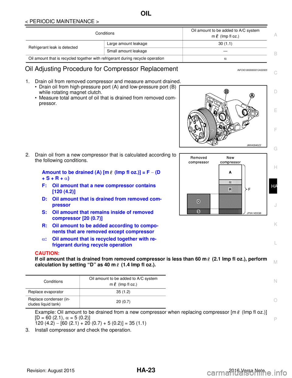
1. Drain oil from removed compressor and measure amount drained. • Drain oil from high-pressure port (A) and low-pressure port (B)
while rotating magnet clutch.
• Measure total amount of oil that is drained from removed com-
pressor.
2. Drain oil from a new compressor that is calculated according to the following conditions.
CAUTION:
If oil amount that is drained from removed compr essor is less than 60 m (2.1 Imp fl oz.), perform
calculation by setting “D” as 40 m (1.4 Imp fl oz.).
Example: Oil amount to be drained from a new compressor when replacing compressor [m (Imp fl oz.)]
[D = 60 (2.1), α = 5 (0.2)]
120 (4.2) − [60 (2.1) + 20 (0.7) + 5 (0.2)] = 35 (1.1)
3. Install compressor and check the operation.
Refrigerant leak is detected Large amount leakage
30 (1.1)
Small amount leakage —
Oil amount that is recycled together with refrigerant during recycle operation α
Conditions
Oil amount to be added to A/C system
m (Imp fl oz.)
JMIIA0940ZZ
Amount to be drained (A) [m (Imp fl oz.)] = F − (D
+ S + R + α)
F: Oil amount that a new compressor contains [120 (4.2)]
D: Oil amount that is drained from removed com- pressor
S: Oil amount that rema ins inside of removed
compressor [20 (0.7)]
R: Oil amount to be added according to compo- nents that are removed except compressor
α : Oil amount that is recycled together with re-
frigerant during recycle operation
Conditions Oil amount to be added to A/C system
m (Imp fl oz.)
Replace evaporator 35 (1.2)
Replace condenser (in-
cludes liquid tank) 20 (0.7)
JPIIA1455GB
Revision: August 2015
2016 Versa Note
cardiagn.com
Page 2051 of 3641

HA-26
< REMOVAL AND INSTALLATION >
COMPRESSOR
REMOVAL AND INSTALLATION
COMPRESSOR
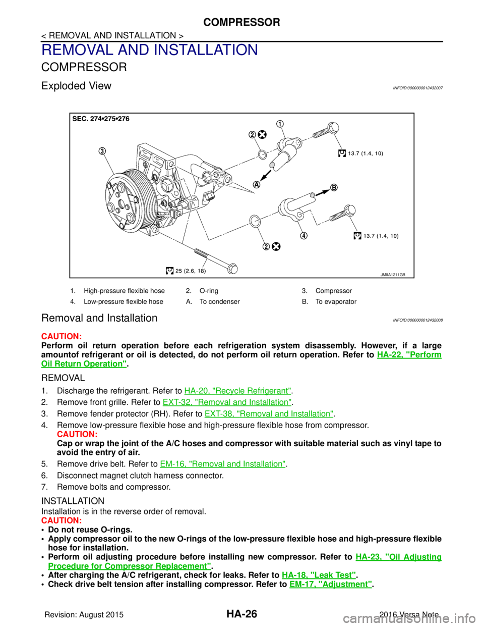
Exploded ViewINFOID:0000000012432007
Removal and InstallationINFOID:0000000012432008
CAUTION:
Perform oil return operation before each refrigeration system disassembly. However, if a large
amountof refrigerant or oil is detected, do not perform oil return operation. Refer to HA-22, "
Perform
Oil Return Operation".
REMOVAL
1. Discharge the refrigerant. Refer to HA-20, "Recycle Refrigerant".
2. Remove front grille. Refer to EXT-32, "
Removal and Installation".
3. Remove fender protector (RH). Refer to EXT-38, "
Removal and Installation".
4. Remove low-pressure flexible hose and high-pressure flexible hose from compressor. CAUTION:
Cap or wrap the joint of the A/C hoses and compr essor with suitable material such as vinyl tape to
avoid the entry of air.
5. Remove drive belt. Refer to EM-16, "
Removal and Installation".
6. Disconnect magnet clutch harness connector.
7. Remove bolts and compressor.
INSTALLATION
Installation is in the reverse order of removal.
CAUTION:
• Do not reuse O-rings.
• Apply compressor oil to the new O-rings of the low-pressure flexible hose an d high-pressure flexible
hose for installation.
• Perform oil adjusting procedure before installing new compressor. Refer to HA-23, "
Oil Adjusting
Procedure for Compressor Replacement".
• After charging the A/C refrig erant, check for leaks. Refer to HA-18, "
Leak Test".
• Check drive belt tension after installing compressor. Refer to EM-17, "
Adjustment".
JMIIA1211GB
1. High-pressure flexible hose 2. O-ring 3. Compressor
4. Low-pressure flexible hose A. To condenser B. To evaporator
Revision: August 2015 2016 Versa Note
cardiagn.com
Page 2052 of 3641

COMPRESSORHA-27
< REMOVAL AND INSTALLATION >
C
DE
F
G H
J
K L
M A
B
HA
N
O P
InspectionINFOID:0000000012432009
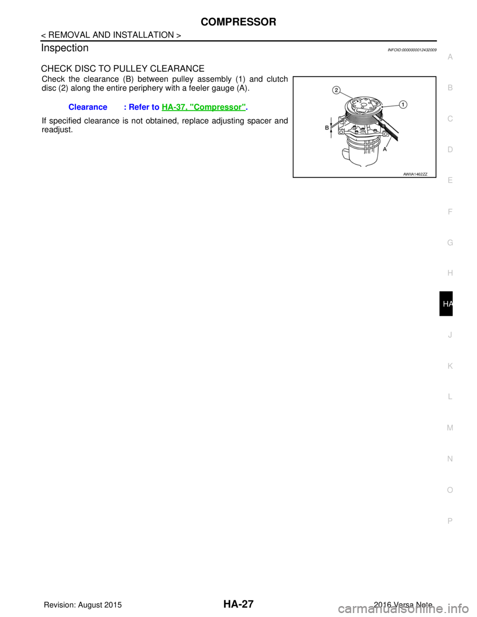
CHECK DISC TO PULLEY CLEARANCE
Check the clearance (B) between pulley assembly (1) and clutch
disc (2) along the entire periphery with a feeler gauge (A).
If specified clearance is not obtained, replace adjusting spacer and
readjust. Clearance : Refer to HA-37, "
Compressor".
AWIIA1462ZZ
Revision: August 2015
2016 Versa Note
cardiagn.com