2016 NISSAN NOTE key
[x] Cancel search: keyPage 2702 of 3641

DOOR SWITCHPWC-41
< DTC/CIRCUIT DIAGNOSIS >
C
DE
F
G H
I
J
L
M A
B
PWC
N
O P
With CONSULT
Check door switches “DOOR SW-DR” and “DOOR SW-AS” in “Data Monitor”.
Is the inspection result normal?
YES >> Door switch is OK.
NO >> Refer to PWC-41, "
WITHOUT INTELLIGENT KEY SY STEM : Diagnosis Procedure".
WITHOUT INTELLIGENT KEY SYSTEM : Diagnosis ProcedureINFOID:0000000012431832
Regarding Wiring Diagram information, refer to PWC-16, "Wiring Diagram".
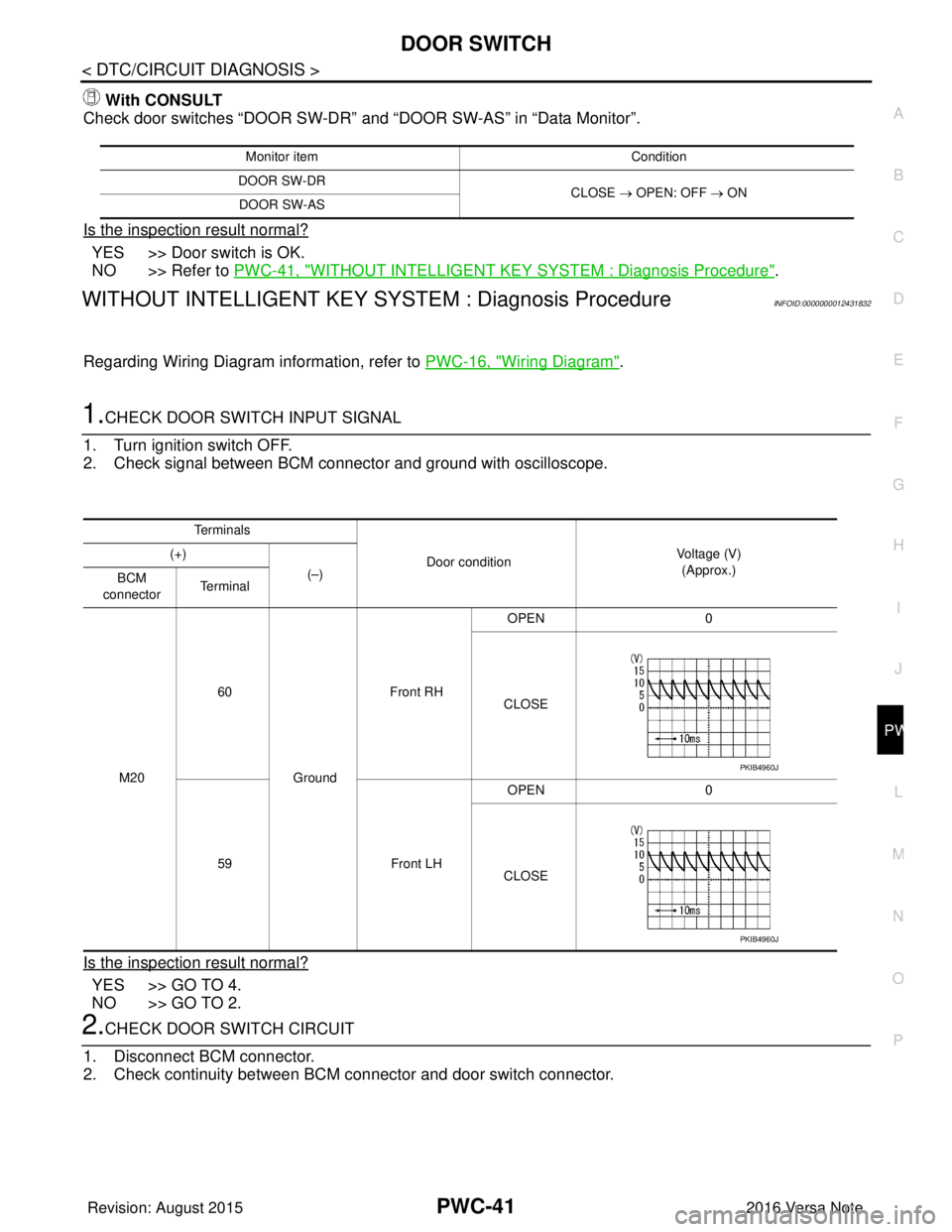
1.CHECK DOOR SWITCH INPUT SIGNAL
1. Turn ignition switch OFF.
2. Check signal between BCM connector and ground with oscilloscope.
Is the inspection result normal?
YES >> GO TO 4.
NO >> GO TO 2.
2.CHECK DOOR SWITCH CIRCUIT
1. Disconnect BCM connector.
2. Check continuity between BCM connector and door switch connector.
Monitor item Condition
DOOR SW-DR CLOSE → OPEN: OFF → ON
DOOR SW-AS
Te r m i n a l s
Door condition Voltage (V)
(Approx.)
(+)
(–)
BCM
connector Te r m i n a l
M20 60
Ground Front RH
OPEN
0
CLOSE
59 Front LHOPEN
0
CLOSE
PKIB4960J
PKIB4960J
Revision: August 2015 2016 Versa Note
cardiagn.com
Page 2703 of 3641

PWC-42
< DTC/CIRCUIT DIAGNOSIS >
DOOR SWITCH
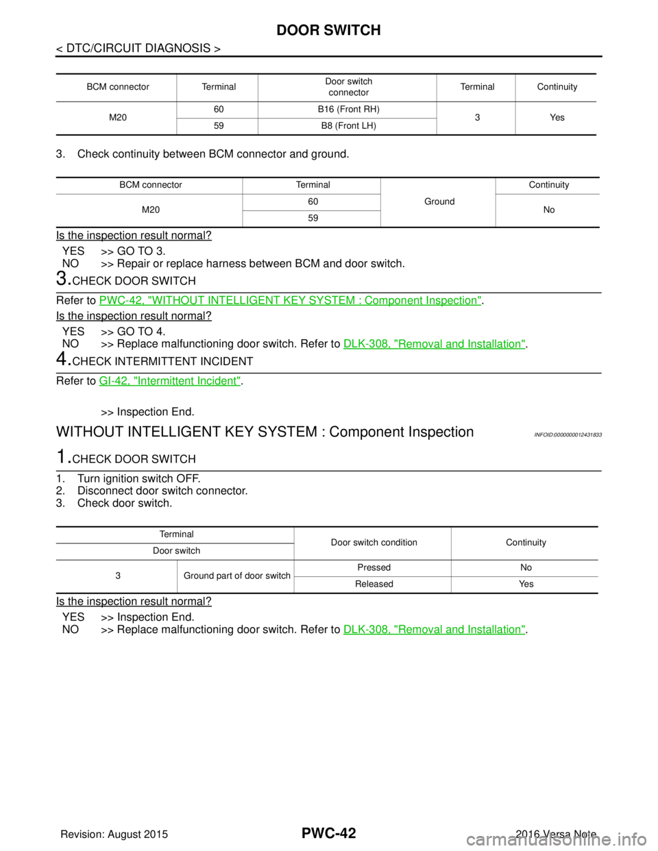
3. Check continuity between BCM connector and ground.
Is the inspection result normal?
YES >> GO TO 3.
NO >> Repair or replace harness between BCM and door switch.
3.CHECK DOOR SWITCH
Refer to PWC-42, "
WITHOUT INTELLIGENT KEY SY STEM : Component Inspection".
Is the inspection result normal?
YES >> GO TO 4.
NO >> Replace malfunctioning door switch. Refer to DLK-308, "
Removal and Installation".
4.CHECK INTERMITTENT INCIDENT
Refer to GI-42, "
Intermittent Incident".
>> Inspection End.
WITHOUT INTELLIGENT KEY SYSTEM : Component InspectionINFOID:0000000012431833
1.CHECK DOOR SWITCH
1. Turn ignition switch OFF.
2. Disconnect door switch connector.
3. Check door switch.
Is the inspection result normal?
YES >> Inspection End.
NO >> Replace malfunctioning door switch. Refer to DLK-308, "
Removal and Installation".
BCM connectorTerminal Door switch
connector Terminal Continuity
M20 60
B16 (Front RH)
3Yes
59 B8 (Front LH)
BCM connector Terminal
GroundContinuity
M20 60
No
59
Te r m i n a l Door switch condition Continuity
Door switch
3 Ground part of door switch Pressed
No
Released Yes
Revision: August 2015 2016 Versa Note
cardiagn.com
Page 2705 of 3641

PWC-44
< SYMPTOM DIAGNOSIS >
NONE OF THE POWER WINDOWS CAN BE OPERATED USING ANY SWITCH
NONE OF THE POWER WINDOWS CAN BE OPERATED USING ANY
SWITCH
Diagnosis ProcedureINFOID:0000000012431835
1.CHECK BCM POWER SUPPLY AND GROUND CIRCUIT
Check BCM power supply and ground circuit. Refer to PWC-25, "
BCM (BODY CONTROL SYSTEM) (WITH
INTELLIGENT KEY SYSTEM) : Diagnosis Procedure" (with Intelligent Key system) or PWC-25, "BCM (BODY
CONTROL SYSTEM) (WITHOUT INTELLIGENT KEY S YSTEM) : Diagnosis Procedure" (without Intelligent
Key system).
Is the inspection result normal?
YES >> GO TO 2.
NO >> Repair or replace the malfunctioning parts.
2.CHECK MAIN POWER WINDOW AND DOOR LOCK /UNLOCK SWITCH POWER SUPPLY AND GROUND
CIRCUIT
Check main power window and door lock/unlock switch power supply and ground circuit.
Refer to PWC-26, "
POWER WINDOW MAIN SWITCH : Diagnosis Procedure".
Is the inspection result normal?
YES >> GO TO 3.
NO >> Repair or replace the malfunctioning parts.
3.CONFIRM THE OPERATION
Confirm the operation again.
Is the result normal?
YES >> Check intermittent incident. Refer to GI-42, "Intermittent Incident".
NO >> GO TO 1.
Revision: August 2015 2016 Versa Note
cardiagn.com
Page 2714 of 3641

POWER WINDOW RETAINED POWER OPERATION DOES NOT OPERATE
PROPERLY
PWC-53
< SYMPTOM DIAGNOSIS >
C
DE
F
G H
I
J
L
M A
B
PWC
N
O P
POWER WINDOW RETAINED POWE R OPERATION DOES NOT OPER-
ATE PROPERLY
Diagnosis ProcedureINFOID:0000000012431847
1. CHECK FRONT DOOR SWITCH
Check front door switch.
Refer to PWC-40, "
WITH INTELLIGENT KEY SYST EM : Component Inspection" (with Intelligent Key system)
or PWC-42, "
WITHOUT INTELLIGENT KEY SYSTEM : Component Inspection" (without Intelligent Key sys-
tem).
Is the inspection result normal?
YES >> Check intermittent incident. Refer to GI-42, "Intermittent Incident".
NO >> Repair or replace the malfunctioning parts.
Revision: August 2015 2016 Versa Note
cardiagn.com
Page 2744 of 3641

WT-1
SUSPENSION
C
DF
G H
I
J
K L
M
SECTION WT
A
B
WT
N
O PCONTENTS
ROAD WHEELS & TIRES
PRECAUTION ....... ........................................3
PRECAUTIONS .............................................. .....3
Precaution for Supplemental Restraint System
(SRS) "AIR BAG" and "SEAT BELT PRE-TEN-
SIONER" ............................................................. ......
3
Service Notice and Precautions for TPMS ................3
Service Notice and Precautions for Road Wheel ......3
PREPARATION ............................................5
PREPARATION .............................................. .....5
Special Service Tool ........................................... ......5
Commercial Service Tool ..........................................5
SYSTEM DESCRIPTION ..............................6
COMPONENT PARTS ................................... .....6
Component Parts Location .................................. ......6
Component Description .............................................6
BCM ..........................................................................6
Remote Keyless Entry Receiver ...............................6
Transmitter ................................................................7
Low Tire Pressure Warning Lamp .............................7
SYSTEM ......................................................... .....8
TIRE PRESSURE MONITORING SYSTEM .......... ......8
TIRE PRESSURE MONITORING SYSTEM : Sys-
tem Diagram ..............................................................
8
TIRE PRESSURE MONITORING SYSTEM : Sys-
tem Description .........................................................
8
TIRE PRESSURE MONITORING SYSTEM :
Easy Fill Tire Alert Function ......................................
8
DIAGNOSIS SYSTEM (BCM) ............................10
WITH INTELLIGENT KEY ..................................... ....10
WITH INTELLIGENT KEY : CONSULT Function
(BCM - COMMON ITEM) ........................................
10
WITH INTELLIGENT KEY : CONSULT Function
(BCM - AIR PRESSURE MONITOR) ......................
11
WITHOUT INTELLIGENT KEY .............................. ....11
WITHOUT INTELLIGENT KEY : CONSULT Func-
tion (BCM - COMMON ITEM) ..................................
11
WITHOUT INTELLIGENT KEY : CONSULT Func-
tion (BCM - AIR PRESSURE MONITOR) ...............
12
ECU DIAGNOSIS INFORMATION ..............14
BCM ...................................................................14
List of ECU Reference ......................................... ....14
WIRING DIAGRAM ......................................15
TIRE PRESSURE MONITORING SYSTEM ......15
Wiring Diagram - With Inte lligent Key ......................15
Wiring Diagram - Without Intelligent Ke y .................18
BASIC INSPECTION ....... ............................21
DIAGNOSIS AND REPAIR WORK FLOW .......21
Work Flow ............................................................ ....21
ID REGISTRATION PROCEDURE ...................22
Description ...............................................................22
Work Procedure .......................................................22
DTC/CIRCUIT DIAGNOSIS .........................25
C1704, C1705, C1706, C1707 LOW TIRE
PRESSURE .......................................................
25
DTC Logic ............................................................ ....25
Diagnosis Procedure ...............................................25
C1708, C1709, C1710, C1711 TRANSMITTER
(NO DATA) ........................................................
27
DTC Logic ............................................................ ....27
Diagnosis Procedure ...............................................27
C1716, C1717, C1718, C1719 TRANSMITTER
(PRESSURE DATA) ..........................................
30
DTC Logic ............................................................ ....30
Diagnosis Procedure ...............................................30
Revision: August 2015 2016 Versa Note
cardiagn.com
Page 2745 of 3641

WT-2
C1729 VEHICLE SPEED SIGNAL ....................32
DTC Logic ............................................................ ...32
Diagnosis Procedure ..............................................32
LOW TIRE PRESSURE WARNING LAMP .......33
Component Function Check ................................ ...33
Diagnosis Procedure ..............................................33
POWER SUPPLY AND GROUND CIRCUIT .....34
WITH INTELLIGENT KEY ...................................... ...34
WITH INTELLIGENT KEY : Diagnosis Procedure ...34
WITHOUT INTELLIGENT KEY .............................. ...34
WITHOUT INTELLIGENT KEY : Diagnosis Proce-
dure ........................................................................
34
SYMPTOM DIAGNOSIS .............................36
TPMS SYMPTOMS ......................................... ...36
Symptom Table ................................................... ...36
LOW TIRE PRESSURE WARNING LAMP
DOES NOT TURN ON .......................................
37
Diagnosis Procedure ..............................................37
LOW TIRE PRESSURE WARNING LAMP
DOES NOT TURN OFF .....................................
38
Diagnosis Procedure ........................................... ...38
LOW TIRE PRESSURE WARNING LAMP
BLINKS ..............................................................
39
Diagnosis Procedure ........................................... ...39
EASY FILL TIRE ALERT DOES NOT ACTI-
VATE ..................................................................
40
Description ........................................................... ...40
Diagnosis Procedure ..............................................40
ID REGISTRATION CANNOT BE COMPLET-
ED ......................................................................
42
Diagnosis Procedure ............................................ ...42
NOISE, VIBRATION AND HARSHNESS
(NVH) TROUBLESHOOTING ............................
43
NVH Troubleshooting Chart ....................................43
PERIODIC MAINTENANCE .......................44
WHEEL ........................................................... ...44
Inspection ............................................................. ...44
WHEEL AND TIRE ............................................45
Adjustment ........................................................... ...45
REMOVAL AND INSTALLATION ..............48
WHEEL AND TIRE ......................................... ...48
Exploded View ..................................................... ...48
Removal and Installation .........................................48
TRANSMITTER .............................................. ...49
Exploded View ..................................................... ...49
Removal and Installation .........................................49
Disposal ............................................................... ...52
TIRE PRESSURE RECEIVER ...........................53
Removal and Installation .........................................53
SERVICE DATA AND SPECIFICATIONS
(SDS) .......... ................................. ...............
54
SERVICE DATA AND SPECIFICATIONS
(SDS) .............................................................. ...
54
Wheel ................................................................... ...54
Tire Air Pressure .....................................................54
Revision: August 2015 2016 Versa Note
cardiagn.com
Page 2748 of 3641

PREPARATIONWT-5
< PREPARATION >
C
DF
G H
I
J
K L
M A
B
WT
N
O P
PREPARATION
PREPARATION
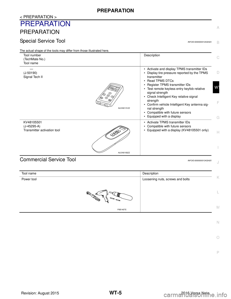
Special Service ToolINFOID:0000000012432424
The actual shape of the tools may di ffer from those illustrated here.
Commercial Service ToolINFOID:0000000012432425
Tool number
(TechMate No.)
Tool name Description
—
(J-50190)
Signal Tech II • Activate and display TPMS transmitter IDs
• Display tire pressure reported by the TPMS
transmitter
• Read TPMS DTCs
• Register TPMS transmitter IDs
• Test remote keyless entry keyfob relative signal strength
• Check Intelligent Key relative signal strength
• Confirm vehicle Intelligent Key antenna sig-
nal strength
• Compatible with future sensors
• Equipped with a display
KV48105501
(J-45295-A)
Transmitter activation tool • Activate TPMS transmitter IDs
• Compatible with future sensors
• Equipped with a display (KV48105501 only)
ALEIA0131ZZ
ALEIA0183ZZ
To o l n a m e
Description
Power tool Loosening nuts, screws and bolts
PIIB1407E
Revision: August 2015 2016 Versa Note
cardiagn.com
Page 2749 of 3641

WT-6
< SYSTEM DESCRIPTION >
COMPONENT PARTS
SYSTEM DESCRIPTION
COMPONENT PARTS
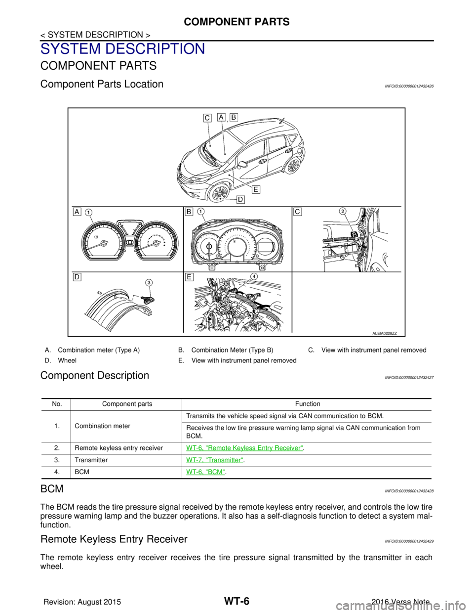
Component Parts LocationINFOID:0000000012432426
Component DescriptionINFOID:0000000012432427
BCMINFOID:0000000012432428
The BCM reads the tire pressure signal received by the remote keyless entry receiver, and controls the low tire
pressure warning lamp and the buzzer operations. It also has a self-diagnosis function to detect a system mal-
function.
Remote Keyless Entry ReceiverINFOID:0000000012432429
The remote keyless entry receiver receives the tire pressure signal transmitted by the transmitter in each
wheel.
ALEIA0228ZZ
A. Combination meter (Type A) B. Combination Meter (Type B)C. View with instrument panel removed
D. Wheel E. View with instrument panel removed
No. Component parts Function
1. Combination meter Transmits the vehicle speed signal via CAN communication to BCM.
Receives the low tire pressure warning lamp signal via CAN communication from
BCM.
2. Remote keyless entry receiver WT-6, "
Remote Keyless Entry Receiver".
3. Transmitter WT-7, "
Transmitter".
4. BCM WT-6, "
BCM".
Revision: August 2015 2016 Versa Note
cardiagn.com