Page 2673 of 3641
PWC-12
< SYSTEM DESCRIPTION >
DIAGNOSIS SYSTEM (BCM) (WITHOUT INTELLIGENT KEY SYSTEM)
RETAINED PWR
RETAINED PWR : CONSULT Function (BCM - RETAINED PWR)INFOID:0000000012542487
DATA MONITOR
WORK SUPPORT
Monitor Item [Unit] Description
IGN ON SW [On/Off] Indicates condition of ignition ON switch.
DOOR SW-DR [On/Off] Indicates condition of front door switch LH.
DOOR SW-AS [On/Off] Indicates condition of front door switch RH.
Monitor Item [Unit] Setting Description
RETAINED PWR SET MODE 3 2 Min.
Sets the retained accessory power operating time.
MODE 2 OFF
MODE 1* 45 Sec.
Revision: August 2015 2016 Versa Note
cardiagn.com
Page 2674 of 3641
BCM
PWC-13
< ECU DIAGNOSIS INFORMATION >
C
D E
F
G H
I
J
L
M A
B
PWC
N
O P
ECU DIAGNOSIS INFORMATION
BCM
List of ECU ReferenceINFOID:0000000012431803
ECU Reference
BCM (with Intelligent Key system) BCS-30, "
Reference Value"
BCS-48, "Fail-safe"
BCS-49, "DTCInspectionPriorityChart"
BCS-50, "DTCIndex"
BCM (without Intelligent Key system)BCS-101, "
Reference Value"
BCS-115, "Fail-safe"
BCS-115, "DTCInspectionPriorityChart"
BCS-115, "DTCIndex"
Revision: August 2015
2016 Versa Note
cardiagn.com
Page 2686 of 3641
POWER SUPPLY AND GROUND CIRCUITPWC-25
< DTC/CIRCUIT DIAGNOSIS >
C
DE
F
G H
I
J
L
M A
B
PWC
N
O P
DTC/CIRCUIT DIAGNOSIS
POWER SUPPLY AND GROUND CIRCUIT
BCM (BODY CONTROL SYSTEM) (W ITH INTELLIGENT KEY SYSTEM)
BCM (BODY CONTROL SYSTEM) (WITH IN TELLIGENT KEY SYSTEM) : Diagnosis
Procedure
INFOID:0000000012542488
Regarding Wiring Diagram information, refer to BCS-52, "Wiring Diagram".
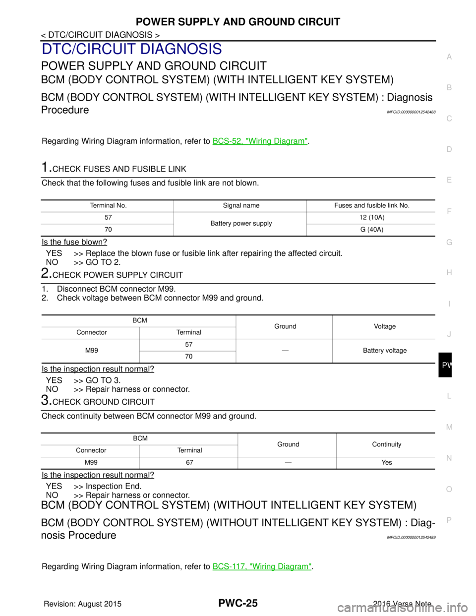
1.CHECK FUSES AND FUSIBLE LINK
Check that the following fuses and fusible link are not blown.
Is the fuse blown?
YES >> Replace the blown fuse or fusible link after repairing the affected circuit.
NO >> GO TO 2.
2.CHECK POWER SUPPLY CIRCUIT
1. Disconnect BCM connector M99.
2. Check voltage between BCM connector M99 and ground.
Is the inspection result normal?
YES >> GO TO 3.
NO >> Repair harness or connector.
3.CHECK GROUND CIRCUIT
Check continuity between BCM connector M99 and ground.
Is the inspection result normal?
YES >> Inspection End.
NO >> Repair harness or connector.
BCM (BODY CONTROL SYSTEM) (WIT HOUT INTELLIGENT KEY SYSTEM)
BCM (BODY CONTROL SYSTEM) (WITHOUT INTELLIGENT KEY SYSTEM) : Diag-
nosis Procedure
INFOID:0000000012542489
Regarding Wiring Diagram information, refer to BCS-117, "Wiring Diagram".
Terminal No.Signal nameFuses and fusible link No.
57 Battery power supply 12 (10A)
70 G (40A)
BCM
Ground Voltage
Connector Terminal
M99 57
— Battery voltage
70
BCM GroundContinuity
Connector Terminal
M99 67—Yes
Revision: August 2015 2016 Versa Note
cardiagn.com
Page 2688 of 3641
POWER SUPPLY AND GROUND CIRCUITPWC-27
< DTC/CIRCUIT DIAGNOSIS >
C
DE
F
G H
I
J
L
M A
B
PWC
N
O P
Is the inspection result normal?
YES >> GO TO 3.
NO >> GO TO 2.
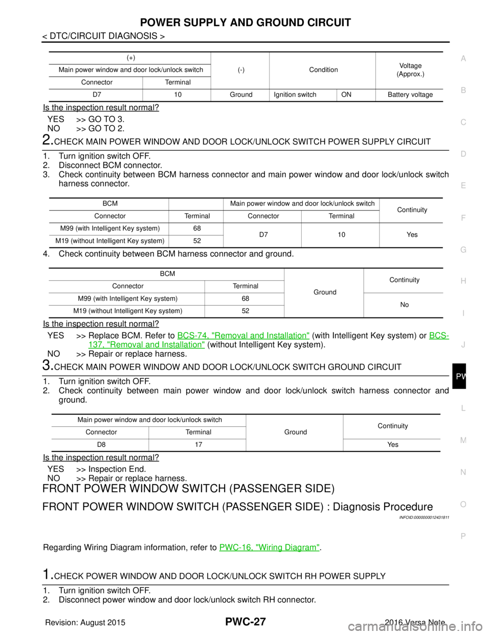
2.CHECK MAIN POWER WINDOW AND DOOR LOCK/UNLOCK SWITCH POWER SUPPLY CIRCUIT
1. Turn ignition switch OFF.
2. Disconnect BCM connector.
3. Check continuity between BCM harness connecto r and main power window and door lock/unlock switch
harness connector.
4. Check continuity between BCM harness connector and ground.
Is the inspection result normal?
YES >> Replace BCM. Refer to BCS-74, "Removal and Installation" (with Intelligent Key system) or BCS-
137, "Removal and Installation" (without Intelligent Key system).
NO >> Repair or replace harness.
3.CHECK MAIN POWER WINDOW AND DOOR LOCK/UNLOCK SWITCH GROUND CIRCUIT
1. Turn ignition switch OFF.
2. Check continuity between main power window and door lock/unlock switch harness connector and ground.
Is the inspection result normal?
YES >> Inspection End.
NO >> Repair or replace harness.
FRONT POWER WINDOW SWIT CH (PASSENGER SIDE)
FRONT POWER WINDOW SWITCH (PASSENG ER SIDE) : Diagnosis Procedure
INFOID:0000000012431811
Regarding Wiring Diagram information, refer to PWC-16, "Wiring Diagram".
1.CHECK POWER WINDOW AND DOOR LOCK/UNLOCK SWITCH RH POWER SUPPLY
1. Turn ignition switch OFF.
2. Disconnect power window and door lock/unlock switch RH connector.
(+)
(-)Condition Vo l ta g e
(Approx.)
Main power window and door lock/unlock switch
Connector Terminal
D7 10Ground Ignition switch ON Battery voltage
BCMMain power window and door lock/unlock switch
Continuity
Connector TerminalConnector Terminal
M99 (with Intelligent Key system) 68 D710Yes
M19 (without Intelligent Key system) 52
BCM GroundContinuity
Connector Terminal
M99 (with Intelligent Key system) 68
No
M19 (without Intelligent Key system) 52
Main power window and door lock/unlock switch
GroundContinuity
Connector Terminal
D8 17 Yes
Revision: August 2015 2016 Versa Note
cardiagn.com
Page 2689 of 3641
PWC-28
< DTC/CIRCUIT DIAGNOSIS >
POWER SUPPLY AND GROUND CIRCUIT
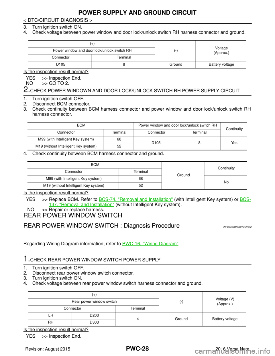
3. Turn ignition switch ON.
4. Check voltage between power window and door lock/unlock switch RH harness connector and ground.
Is the inspection result normal?
YES >> Inspection End.
NO >> GO TO 2.
2.CHECK POWER WINDOWN AND DOOR LOCK/UNLOCK SWITCH RH POWER SUPPLY CIRCUIT
1. Turn ignition switch OFF.
2. Disconnect BCM connector.
3. Check continuity between BCM harness connector and power window and door lock/unlock switch RH harness connector.
4. Check continuity between BCM harness connector and ground.
Is the inspection result normal?
YES >> Replace BCM. Refer to BCS-74, "Removal and Installation" (with Intelligent Key system) or BCS-
137, "Removal and Installation" (without Intelligent Key system).
NO >> Repair or replace harness.
REAR POWER WINDOW SWITCH
REAR POWER WINDOW SW ITCH : Diagnosis ProcedureINFOID:0000000012431812
Regarding Wiring Diagram information, refer to PWC-16, "Wiring Diagram".
1.CHECK REAR POWER WINDOW SWITCH POWER SUPPLY
1. Turn ignition switch OFF.
2. Disconnect rear power window switch connector.
3. Turn ignition switch ON.
4. Check voltage between rear power window switch harness connector and ground.
Is the inspection result normal?
YES >> Inspection End.
(+)
(-)Vo l ta g e
(Approx.)
Power window and door lock/unlock switch RH
Connector Terminal
D105 8GroundBattery voltage
BCM Power window and door lock/unlock switch RH
Continuity
Connector Terminal Connector Terminal
M99 (with Intelligent Key system) 68
D105 8Yes
M19 (without Intelligent Key system) 52
BCM GroundContinuity
Connector Terminal
M99 (with Intelligent Key system) 68
No
M19 (without Intelligent Key system) 52
(+)
(-)Voltage (V)
(Approx.)
Rear power window switch
Connector Terminal
LH D203
4GroundBattery voltage
RH D303
Revision: August 2015 2016 Versa Note
cardiagn.com
Page 2690 of 3641
POWER SUPPLY AND GROUND CIRCUITPWC-29
< DTC/CIRCUIT DIAGNOSIS >
C
DE
F
G H
I
J
L
M A
B
PWC
N
O P
NO >> GO TO 2.
2.CHECK REAR POWER WINDOW SWITCH POWER SUPPLY CIRCUIT
1. Turn ignition switch OFF.
2. Disconnect BCM connector.
3. Check continuity between BCM harness connector and rear power window switch harness connector.
4. Check continuity between BCM harness connector and ground.
Is the inspection result normal?
YES >> Replace BCM. Refer to BCS-74, "Removal and Installation" (with Intelligent Key system) or BCS-
137, "Removal and Installation" (without Intelligent Key system).
NO >> Repair or replace harness.
BCM Rear power window switch
Continuity
Connector TerminalConnector Terminal
M99 (with Intelligent Key system) 68LH
D203
4Yes
RH
D303
M19 (without Intelligent Key system) 52 LH
D203
RH D303
BCM GroundContinuity
Connector Terminal
M99 (with Intelligent Key system) 68
No
M19 (without Intelligent Key system) 52
Revision: August 2015 2016 Versa Note
cardiagn.com
Page 2700 of 3641
DOOR SWITCHPWC-39
< DTC/CIRCUIT DIAGNOSIS >
C
DE
F
G H
I
J
L
M A
B
PWC
N
O P
DOOR SWITCH
WITH INTELLIGENT KEY SYSTEM
WITH INTELLIGENT KEY SYST EM : Component Function CheckINFOID:0000000012431827
1.CHECK FUNCTION
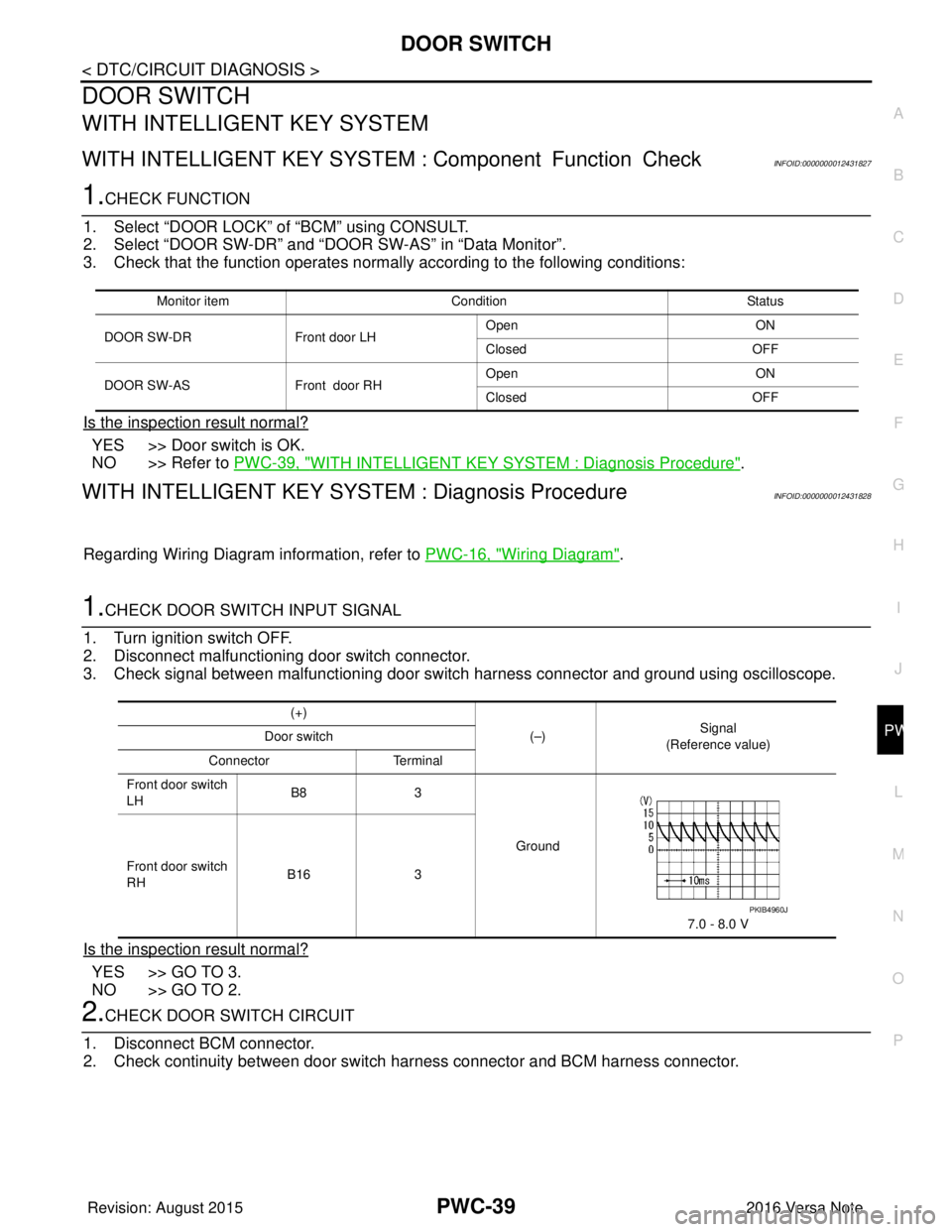
1. Select “DOOR LOCK” of “BCM” using CONSULT.
2. Select “DOOR SW-DR” and “DOOR SW-AS” in “Data Monitor”.
3. Check that the function operates normall y according to the following conditions:
Is the inspection result normal?
YES >> Door switch is OK.
NO >> Refer to PWC-39, "
WITH INTELLIGENT KEY SYSTEM : Diagnosis Procedure".
WITH INTELLIGENT KEY SYST EM : Diagnosis ProcedureINFOID:0000000012431828
Regarding Wiring Diagram information, refer to PWC-16, "Wiring Diagram".
1.CHECK DOOR SWITCH INPUT SIGNAL
1. Turn ignition switch OFF.
2. Disconnect malfunctioning door switch connector.
3. Check signal between malfunctioning door switch harness connector and ground using oscilloscope.
Is the inspection result normal?
YES >> GO TO 3.
NO >> GO TO 2.
2.CHECK DOOR SWITCH CIRCUIT
1. Disconnect BCM connector.
2. Check continuity between door switch harness connector and BCM harness connector.
Monitor item Condition Status
DOOR SW-DR Front door LH Open
ON
Closed OFF
DOOR SW-AS Front door RHOpen
ON
Closed OFF
(+)
(–)Signal
(Reference value)
Door switch
Connector Terminal
Front door switch
LH B8
3
Ground
7.0 - 8.0 V
Front door switch
RH
B16
3
PKIB4960J
Revision: August 2015 2016 Versa Note
cardiagn.com
Page 2701 of 3641
PWC-40
< DTC/CIRCUIT DIAGNOSIS >
DOOR SWITCH
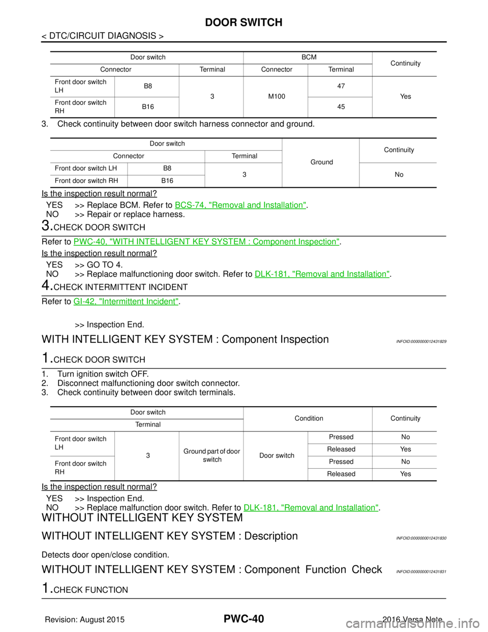
3. Check continuity between door switch harness connector and ground.
Is the inspection result normal?
YES >> Replace BCM. Refer to BCS-74, "Removal and Installation".
NO >> Repair or replace harness.
3.CHECK DOOR SWITCH
Refer to PWC-40, "
WITH INTELLIGENT KEY SYSTEM : Component Inspection".
Is the inspection result normal?
YES >> GO TO 4.
NO >> Replace malfunctioning door switch. Refer to DLK-181, "
Removal and Installation".
4.CHECK INTERMITTENT INCIDENT
Refer to GI-42, "
Intermittent Incident".
>> Inspection End.
WITH INTELLIGENT KEY SYST EM : Component InspectionINFOID:0000000012431829
1.CHECK DOOR SWITCH
1. Turn ignition switch OFF.
2. Disconnect malfunctioning door switch connector.
3. Check continuity between door switch terminals.
Is the inspection result normal?
YES >> Inspection End.
NO >> Replace malfunction door switch. Refer to DLK-181, "
Removal and Installation".
WITHOUT INTELLIGENT KEY SYSTEM
WITHOUT INTELLIGENT KEY SYSTEM : DescriptionINFOID:0000000012431830
Detects door open/close condition.
WITHOUT INTELLIGENT KEY SYSTEM : Component Function CheckINFOID:0000000012431831
1.CHECK FUNCTION
Door switch BCM
Continuity
Connector TerminalConnector Terminal
Front door switch
LH B8
3M100 47
Ye s
Front door switch
RH B16
45
Door switch GroundContinuity
Connector Terminal
Front door switch LH B8
3N o
Front door switch RH B16
Door switch
Condition Continuity
Te r m i n a l
Front door switch
LH 3Ground part of door
switch Door switch Pressed
No
Released Yes
Front door switch
RH Pressed
No
Released Yes
Revision: August 2015 2016 Versa Note
cardiagn.com