2016 NISSAN NOTE wiring
[x] Cancel search: wiringPage 2770 of 3641
C1708, C1709, C1710, C1711 TRANSMITTER (NO DATA)
WT-27
< DTC/CIRCUIT DIAGNOSIS >
C
DF
G H
I
J
K L
M A
B
WT
N
O P
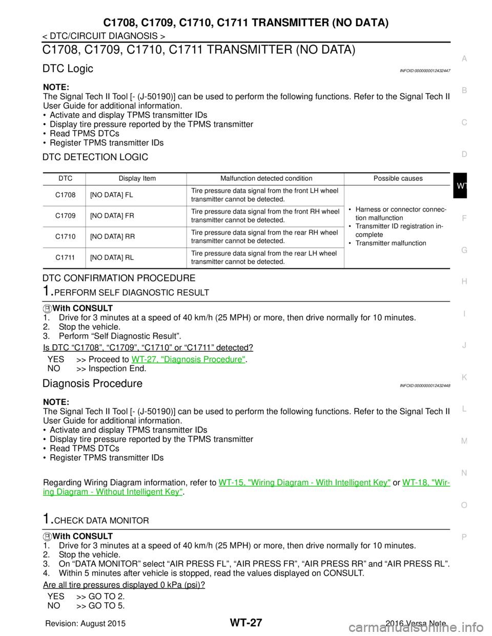
C1708, C1709, C1710, C1711 TRANSMITTER (NO DATA)
DTC LogicINFOID:0000000012432447
NOTE:
The Signal Tech II Tool [- (J-50190)] can be used to perform the following functions. Refer to the Signal Tech II
User Guide for additional information.
• Activate and display TPMS transmitter IDs
• Display tire pressure repor ted by the TPMS transmitter
• Read TPMS DTCs
• Register TPMS transmitter IDs
DTC DETECTION LOGIC
DTC CONFIRMATION PROCEDURE
1.PERFORM SELF DIAGNOSTIC RESULT
With CONSULT
1. Drive for 3 minutes at a speed of 40 km/h (25 MPH) or more, then drive normally for 10 minutes.
2. Stop the vehicle.
3. Perform “Self Diagnostic Result”.
Is DTC
“C1708”, “C1709”, “C1710” or “C1711” detected?
YES >> Proceed to WT-27, "Diagnosis Procedure".
NO >> Inspection End.
Diagnosis ProcedureINFOID:0000000012432448
NOTE:
The Signal Tech II Tool [- (J-50190)] can be used to perform the following functions. Refer to the Signal Tech II
User Guide for additional information.
• Activate and display TPMS transmitter IDs
• Display tire pressure repor ted by the TPMS transmitter
• Read TPMS DTCs
• Register TPMS transmitter IDs
Regarding Wiring Diagram information, refer to WT-15, "
Wiring Diagram - With Intelligent Key" or WT-18, "Wir-
ing Diagram - Without Intelligent Key".
1.CHECK DATA MONITOR
With CONSULT
1. Drive for 3 minutes at a speed of 40 km/h (25 MPH) or more, then drive normally for 10 minutes.
2. Stop the vehicle.
3. On “DATA MONITOR” select “AIR PRESS FL”, “AIR PRESS FR”, “AIR PRESS RR” and “AIR PRESS RL”.
4. Within 5 minutes after vehicle is stopped, read the values displayed on CONSULT.
Are all tire pressures displayed 0 kPa (psi)?
YES >> GO TO 2.
NO >> GO TO 5.
DTC Display Item Malfunction detected condition Possible causes
C1708 [NO DATA] FL Tire pressure data signal from the front LH wheel
transmitter cannot be detected.
• Harness or connector connec-tion malfunction
• Transmitter ID registration in- complete
• Transmitter malfunction
C1709 [NO DATA] FR
Tire pressure data signal from the front RH wheel
transmitter cannot be detected.
C1710 [NO DATA] RR Tire pressure data signal from the rear RH wheel
transmitter cannot be detected.
C1711 [NO DATA] RL Tire pressure data signal from the rear LH wheel
transmitter cannot be detected.
Revision: August 2015
2016 Versa Note
cardiagn.com
Page 2777 of 3641
WT-34
< DTC/CIRCUIT DIAGNOSIS >
POWER SUPPLY AND GROUND CIRCUIT
POWER SUPPLY AND GROUND CIRCUIT
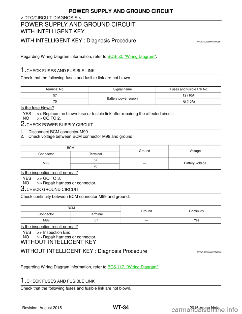
WITH INTELLIGENT KEY
WITH INTELLIGENT KEY : Diagnosis ProcedureINFOID:0000000012542961
Regarding Wiring Diagram information, refer to BCS-52, "Wiring Diagram".
1.CHECK FUSES AND FUSIBLE LINK
Check that the following fuses and fusible link are not blown.
Is the fuse blown?
YES >> Replace the blown fuse or fusible link after repairing the affected circuit.
NO >> GO TO 2.
2.CHECK POWER SUPPLY CIRCUIT
1. Disconnect BCM connector M99.
2. Check voltage between BCM connector M99 and ground.
Is the inspection result normal?
YES >> GO TO 3.
NO >> Repair harness or connector.
3.CHECK GROUND CIRCUIT
Check continuity between BCM connector M99 and ground.
Is the inspection result normal?
YES >> Inspection End.
NO >> Repair harness or connector.
WITHOUT INTELLIGENT KEY
WITHOUT INTELLIGENT KEY : Diagnosis ProcedureINFOID:0000000012542962
Regarding Wiring Diagram information, refer to BCS-117, "Wiring Diagram".
1.CHECK FUSES AND FUSIBLE LINK
Check that the following fuses and fusible link are not blown.
Terminal No. Signal nameFuses and fusible link No.
57 Battery power supply 12 (10A)
70 G (40A)
BCM
Ground Voltage
Connector Terminal
M99 57
— Battery voltage
70
BCM GroundContinuity
Connector Terminal
M99 67—Yes
Revision: August 2015 2016 Versa Note
cardiagn.com
Page 2783 of 3641
WT-40
< SYMPTOM DIAGNOSIS >
EASY FILL TIRE ALERT DOES NOT ACTIVATE
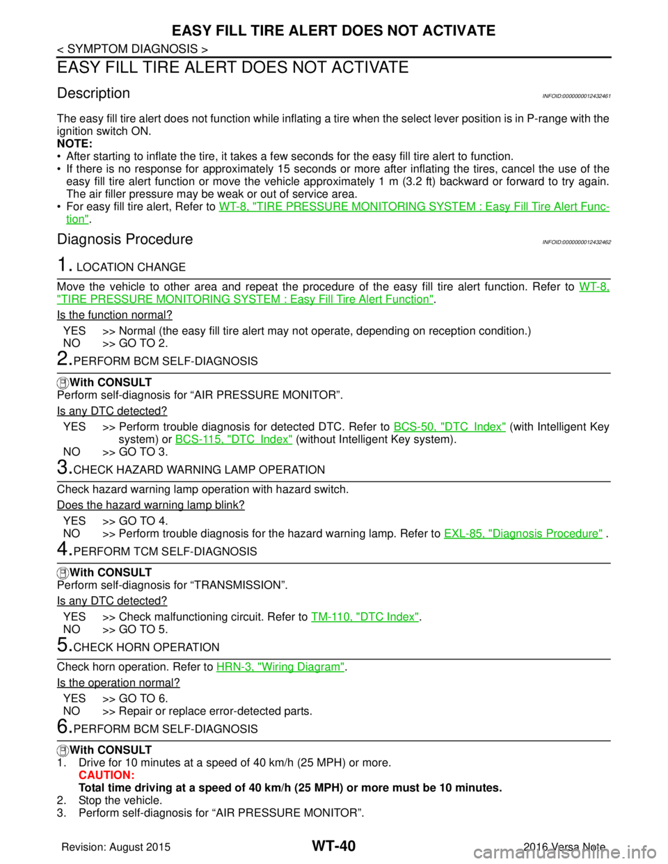
EASY FILL TIRE ALERT DOES NOT ACTIVATE
DescriptionINFOID:0000000012432461
The easy fill tire alert does not function while inflating a tire when the select lever position is in P-range with the
ignition switch ON.
NOTE:
• After starting to inflate the tire, it takes a few seconds for the easy fill tire alert to function.
• If there is no response for approximately 15 seconds or mo re after inflating the tires, cancel the use of the
easy fill tire alert function or move the vehicle approximately 1 m (3.2 ft) backward or forward to try again.
The air filler pressure may be weak or out of service area.
• For easy fill tire alert, Refer to WT-8, "
TIRE PRESSURE MONITORING SYST EM : Easy Fill Tire Alert Func-
tion".
Diagnosis ProcedureINFOID:0000000012432462
1. LOCATION CHANGE
Move the vehicle to other area and repeat the procedure of the easy fill tire alert function. Refer to WT-8,
"TIRE PRESSURE MONITORING SYSTEM : Easy Fill Tire Alert Function".
Is the function normal?
YES >> Normal (the easy fill tire alert may not operate, depending on reception condition.)
NO >> GO TO 2.
2.PERFORM BCM SELF-DIAGNOSIS
With CONSULT
Perform self-diagnosis for “AIR PRESSURE MONITOR”.
Is any DTC detected?
YES >> Perform trouble diagnosis for detected DTC. Refer to BCS-50, "DTCIndex" (with Intelligent Key
system) or BCS-115, "
DTCIndex" (without Intelligent Key system).
NO >> GO TO 3.
3.CHECK HAZARD WARNING LAMP OPERATION
Check hazard warning lamp operation with hazard switch.
Does the hazard warning lamp blink?
YES >> GO TO 4.
NO >> Perform trouble diagnosis for the hazard warning lamp. Refer to EXL-85, "
Diagnosis Procedure" .
4.PERFORM TCM SELF-DIAGNOSIS
With CONSULT
Perform self-diagnosis for “TRANSMISSION”.
Is any DTC detected?
YES >> Check malfunctioning circuit. Refer to TM-110, "DTC Index".
NO >> GO TO 5.
5.CHECK HORN OPERATION
Check horn operation. Refer to HRN-3, "
Wiring Diagram".
Is the operation normal?
YES >> GO TO 6.
NO >> Repair or replace error-detected parts.
6.PERFORM BCM SELF-DIAGNOSIS
With CONSULT
1. Drive for 10 minutes at a speed of 40 km/h (25 MPH) or more.
CAUTION:
Total time driving at a speed of 40 km/h (25 MPH) or more must be 10 minutes.
2. Stop the vehicle.
3. Perform self-diagnosis for “AIR PRESSURE MONITOR”.
Revision: August 2015 2016 Versa Note
cardiagn.com
Page 2799 of 3641
SB-2
< PRECAUTION >
PRECAUTIONS
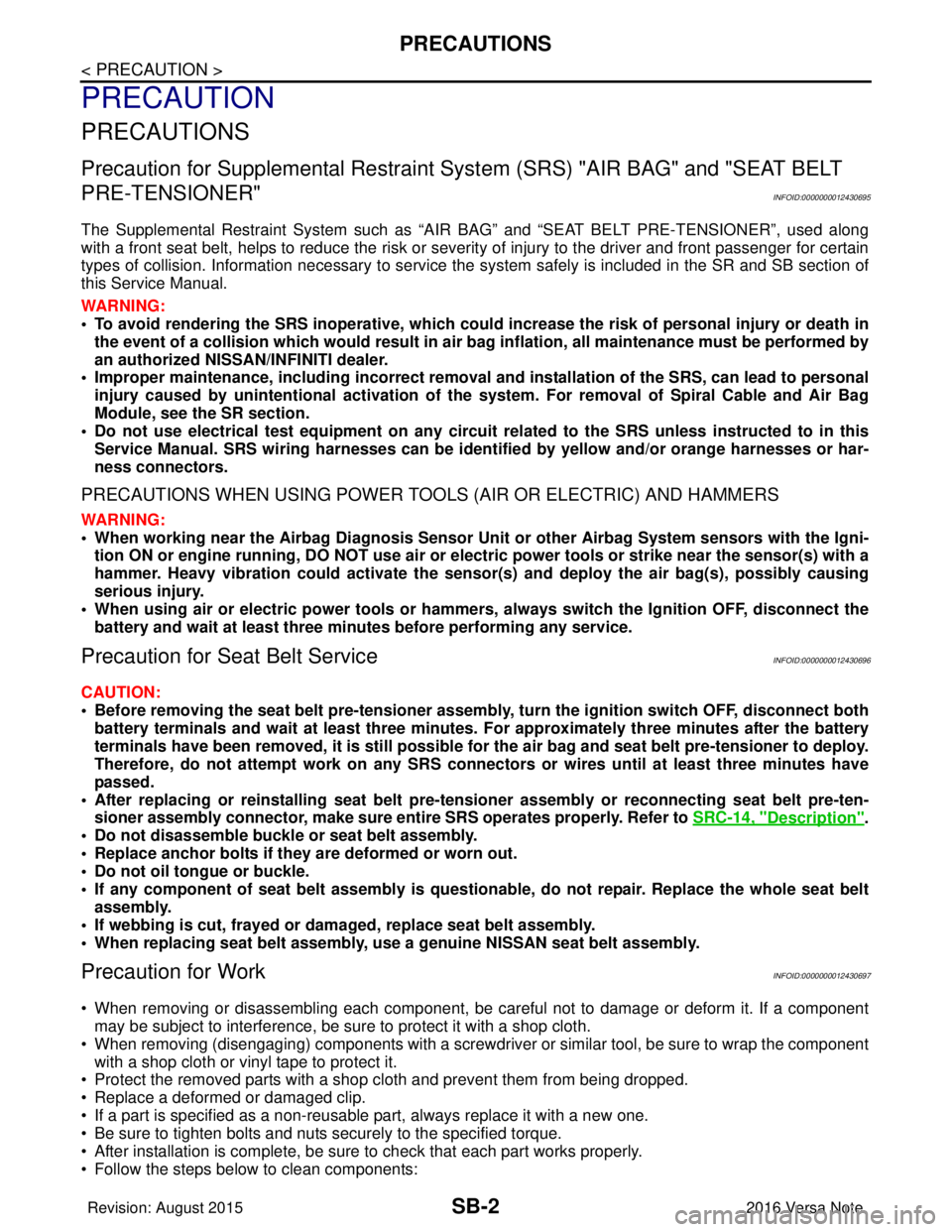
PRECAUTION
PRECAUTIONS
Precaution for Supplemental Restraint System (SRS) "AIR BAG" and "SEAT BELT
PRE-TENSIONER"
INFOID:0000000012430695
The Supplemental Restraint System such as “A IR BAG” and “SEAT BELT PRE-TENSIONER”, used along
with a front seat belt, helps to reduce the risk or severity of injury to the driver and front passenger for certain
types of collision. Information necessary to service the system safely is included in the SR and SB section of
this Service Manual.
WARNING:
• To avoid rendering the SRS inopera tive, which could increase the risk of personal injury or death in
the event of a collision which would result in air bag inflation, all maintenance must be performed by
an authorized NISSAN/INFINITI dealer.
• Improper maintenance, including in correct removal and installation of the SRS, can lead to personal
injury caused by unintent ional activation of the system. For re moval of Spiral Cable and Air Bag
Module, see the SR section.
• Do not use electrical test equipmen t on any circuit related to the SRS unless instructed to in this
Service Manual. SRS wiring harn esses can be identified by yellow and/or orange harnesses or har-
ness connectors.
PRECAUTIONS WHEN USING POWER TOOLS (AIR OR ELECTRIC) AND HAMMERS
WARNING:
• When working near the Airbag Diagnosis Sensor Unit or other Airbag System sensors with the Igni-
tion ON or engine running, DO NOT use air or electri c power tools or strike near the sensor(s) with a
hammer. Heavy vibration could activate the sensor( s) and deploy the air bag(s), possibly causing
serious injury.
• When using air or electric power tools or hammers , always switch the Ignition OFF, disconnect the
battery and wait at least three minutes before performing any service.
Precaution for Seat Belt ServiceINFOID:0000000012430696
CAUTION:
• Before removing the seat belt pre-tensioner assembl y, turn the ignition switch OFF, disconnect both
battery terminals and wait at least three minutes. For approximately three minutes after the battery
terminals have been removed, it is still possible for the air bag and seat belt pre-tensioner to deploy.
Therefore, do not attempt work on any SRS connectors or wires until at least three minutes have
passed.
• After replacing or reinstalling seat belt pre -tensioner assembly or reconnecting seat belt pre-ten-
sioner assembly connector, make sure entire SRS operates properly. Refer to SRC-14, "
Description".
• Do not disassemble buckle or seat belt assembly.
• Replace anchor bolts if th ey are deformed or worn out.
• Do not oil tongue or buckle.
• If any component of seat belt assembly is questionable, do not re pair. Replace the whole seat belt
assembly.
• If webbing is cut, frayed or damaged, replace seat belt assembly.
• When replacing seat belt assembly, use a genuine NISSAN seat belt assembly.
Precaution for WorkINFOID:0000000012430697
• When removing or disassembling each component, be careful not to damage or deform it. If a component may be subject to interference, be sure to protect it with a shop cloth.
• When removing (disengaging) components with a screwdriver or similar tool, be sure to wrap the component with a shop cloth or vinyl tape to protect it.
• Protect the removed parts with a shop cloth and prevent them from being dropped.
• Replace a deformed or damaged clip.
• If a part is specified as a non-reusable part, always replace it with a new one.
• Be sure to tighten bolts and nuts securely to the specified torque.
• After installation is complete, be sure to check that each part works properly.
• Follow the steps below to clean components:
Revision: August 2015 2016 Versa Note
cardiagn.com
Page 2814 of 3641

SE-1
BODY INTERIOR
C
DE
F
G H
I
K L
M
SECTION SE
A
B
SE
N
O P
CONTENTS
SEAT
PRECAUTION ....... ........................................2
PRECAUTIONS .............................................. .....2
Precaution for Supplemental Restraint System
(SRS) "AIR BAG" and "SEAT BELT PRE-TEN-
SIONER" ............................................................. ......
2
Precaution for Work ..................................................2
PREPARATION ............................................3
PREPARATION .............................................. .....3
Special Service Tools .......................................... ......3
Commercial Service Tools ........................................3
CLIP LIST ............................................................4
Descriptions for Clips ................................................4
SYMPTOM DIAGNOSIS ...............................8
SQUEAK AND RATTLE TROUBLE DIAG-
NOSES ........................ ........................................
8
Work Flow ........................................................... ......8
Generic Squeak and Rattle Troubleshooting ............9
Diagnostic Worksheet .............................................12
WIRING DIAGRAM ......................................14
HEATED SEAT SYSTEM ...................................14
Wiring Diagram ................................................... ....14
REMOVAL AND INSTALLATION ...............18
FRONT SEAT ................................................. ....18
DRIVER SIDE ........................................................ ....18
DRIVER SIDE : Exploded View ..............................18
DRIVER SIDE : Removal and Installation ...............20
PASSENGER SIDE ...................................................20
PASSENGER SIDE : Exploded View .................. ....21
PASSENGER SIDE : Removal and Installation ......22
REAR SEAT ......................................................23
Exploded View ..................................................... ....23
SEAT CUSHION .................................................... ....26
SEAT CUSHION : Removal and Installation ...........26
SEATBACK ............................................................ ....26
SEATBACK : Removal and Installation ...................26
SEATBACK HINGE ............................................... ....27
SEATBACK HINGE : Removal and Installation .......27
SEATBACK STRIKER ........................................... ....27
SEATBACK STRIKER : Removal and Installation ....27
SEAT CUSHION HOOK ......................................... ....27
SEAT CUSHION HOOK : Removal and Installa-
tion ...........................................................................
27
FRONT HEATED SEAT SWITCH .....................29
Removal and Installation .........................................29
UNIT DISASSEMBLY AND ASSEMBLY ....30
FRONT SEAT ....................................................30
DRIVER SIDE ......................................................... ....30
DRIVER SIDE : Exploded View ...............................30
DRIVER SIDE : Seatback ........................................32
DRIVER SIDE : Seat Cushion .................................33
PASSENGER SIDE ....................................................34
PASSENGER SIDE : Explode d View ......................35
PASSENGER SIDE : Seatback ...............................36
PASSENGER SIDE : Seat Cushion ........................36
REAR SEAT ......................................................38
Exploded View ..................................................... ....38
Seat Cushion ...........................................................41
Seatback ..................................................................42
Revision: August 2015 2016 Versa Note
cardiagn.com
Page 2815 of 3641

SE-2
< PRECAUTION >
PRECAUTIONS
PRECAUTION
PRECAUTIONS
Precaution for Supplemental Restraint System (SRS) "AIR BAG" and "SEAT BELT
PRE-TENSIONER"
INFOID:0000000012432026
The Supplemental Restraint System such as “A IR BAG” and “SEAT BELT PRE-TENSIONER”, used along
with a front seat belt, helps to reduce the risk or severity of injury to the driver and front passenger for certain
types of collision. Information necessary to service the system safely is included in the SR and SB section of
this Service Manual.
WARNING:
• To avoid rendering the SRS inopera tive, which could increase the risk of personal injury or death in
the event of a collision which would result in air bag inflation, all maintenance must be performed by
an authorized NISSAN/INFINITI dealer.
• Improper maintenance, including in correct removal and installation of the SRS, can lead to personal
injury caused by unintent ional activation of the system. For re moval of Spiral Cable and Air Bag
Module, see the SR section.
• Do not use electrical test equipmen t on any circuit related to the SRS unless instructed to in this
Service Manual. SRS wiring harn esses can be identified by yellow and/or orange harnesses or har-
ness connectors.
PRECAUTIONS WHEN USING POWER TOOLS (AIR OR ELECTRIC) AND HAMMERS
WARNING:
• When working near the Airbag Diagnosis Sensor Unit or other Airbag System sensors with the Igni-
tion ON or engine running, DO NOT use air or electri c power tools or strike near the sensor(s) with a
hammer. Heavy vibration could activate the sensor( s) and deploy the air bag(s), possibly causing
serious injury.
• When using air or electric power tools or hammers , always switch the Ignition OFF, disconnect the
battery and wait at least three minutes before performing any service.
Precaution for WorkINFOID:0000000012432027
• When removing or disassembling each component, be careful not to damage or deform it. If a component may be subject to interference, be sure to protect it with a shop cloth.
• When removing (disengaging) components with a screwdriver or similar tool, be sure to wrap the component with a shop cloth or vinyl tape to protect it.
• Protect the removed parts with a shop cloth and prevent them from being dropped.
• Replace a deformed or damaged clip.
• If a part is specified as a non-reusable part, always replace it with a new one.
• Be sure to tighten bolts and nuts securely to the specified torque.
• After installation is complete, be sure to check that each part works properly.
• Follow the steps below to clean components:
- Water soluble dirt:
• Dip a soft cloth into lukewarm water, wring the water out of the cloth and wipe the dirty area.
• Then rub with a soft, dry cloth.
- Oily dirt:
• Dip a soft cloth into lukewarm water with mild detergent (concentration: within 2 to 3%) and wipe the dirty area.
• Then dip a cloth into fresh water, wring the water out of the cloth and wipe the detergent off.
• Then rub with a soft, dry cloth.
- Do not use organic solvent such as thinner, benzene, alcohol or gasoline.
- For genuine leather seats, use a genuine leather seat cleaner.
Revision: August 2015 2016 Versa Note
cardiagn.com
Page 2823 of 3641

SE-10
< SYMPTOM DIAGNOSIS >
SQUEAK AND RATTLE TROUBLE DIAGNOSES
INSTRUMENT PANEL
Most incidents are caused by contact and movement between:
1. Cluster lid A and the instrument panel
2. Acrylic lens and combination meter housing
3. Instrument panel to front pillar finisher
4. Instrument panel to windshield
5. Instrument panel pins
6. Wiring harnesses behind the combination meter
7. A/C defroster duct and duct joint
These incidents can usually be located by tapping or moving the components to duplicate the noise or by
pressing on the components while driving to stop the noise. Most of these incidents can be repaired by apply-
ing felt cloth tape or silicone spray (in hard to reach areas). Urethane pads can be used to insulate wiring har-
ness.
CAUTION:
Do not use silicone spray to isolate a squeak or rattle. If you saturate the ar ea with silicone, you will
not be able to recheck the repair.
CENTER CONSOLE
Components to pay attention to include:
1. Shift selector assembly cover to finisher
2. A/C control unit and cluster lid C
3. Wiring harnesses behind audio and A/C control unit
The instrument panel repair and isolation pr ocedures also apply to the center console.
DOORS
Pay attention to the:
1. Finisher and inner panel making a slapping noise
2. Inside handle escutcheon to door finisher
3. Wiring harnesses tapping
4. Door striker out of alignment causing a popping noise on starts and stops
Tapping or moving the components or pressing on them wh ile driving to duplicate the conditions can isolate
many of these incidents. You can usually insulate the areas with felt cloth tape or insulator foam blocks from
the NISSAN Squeak and Rattle Kit (J-50397) to repair the noise.
TRUNK
Trunk noises are often caused by a loose jack or loose items put into the trunk by the owner.
In addition look for:
1. Trunk lid bumpers out of adjustment
2. Trunk lid striker out of adjustment
3. The trunk lid torsion bars knocking together
4. A loose license plate or bracket
Most of these incidents can be repaired by adjusting, se curing or insulating the item(s) or component(s) caus-
ing the noise.
SUNROOF/HEADLINING
Noises in the sunroof/headlining area c an often be traced to one of the following:
1. Sunroof lid, rail, linkage or seals making a rattle or light knocking noise
2. Sun visor shaft shaking in the holder
3. Front or rear windshield touching headlining and squeaking
Again, pressing on the components to stop the noise while duplicating the conditions can isolate most of these
incidents. Repairs usually consist of insulating with felt cloth tape.
OVERHEAD CONSOLE (FRONT AND REAR)
Overhead console noises are often caused by the c onsole panel clips not being engaged correctly. Most of
these incidents are repaired by pushing up on the c onsole at the clip locations until the clips engage.
In addition look for:
Revision: August 2015 2016 Versa Note
cardiagn.com
Page 2827 of 3641
SE-14
< WIRING DIAGRAM >
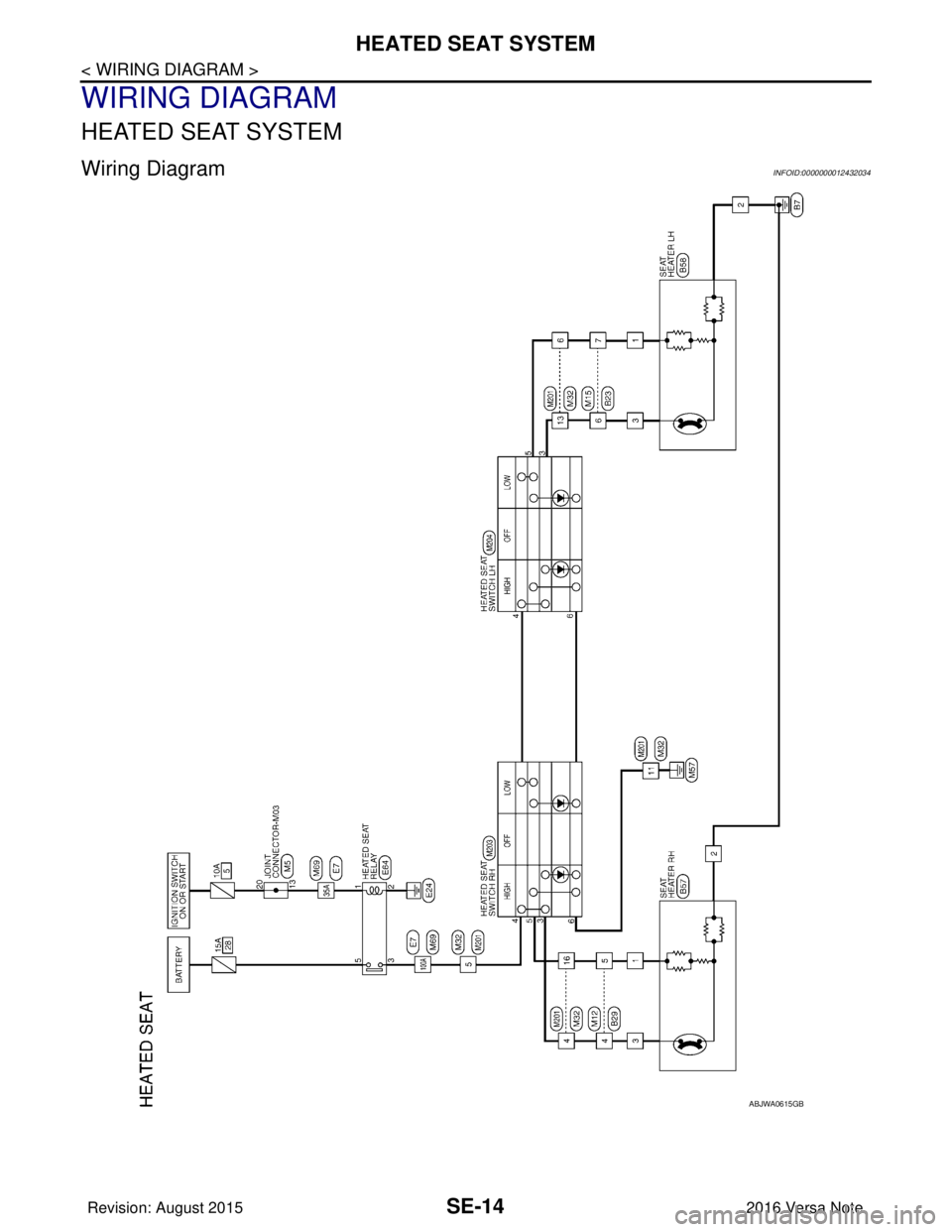
HEATED SEAT SYSTEM
WIRING DIAGRAM
HEATED SEAT SYSTEM
Wiring DiagramINFOID:0000000012432034
ABJWA0615GB
Revision: August 20152016 Versa Note
cardiagn.com