2016 NISSAN NOTE wiring
[x] Cancel search: wiringPage 2695 of 3641
PWC-34
< DTC/CIRCUIT DIAGNOSIS >
POWER WINDOW MOTOR
POWER WINDOW MOTOR
DRIVER SIDE
DRIVER SIDE : Component Function CheckINFOID:0000000012431819
1. CHECK FUNCTION
Check front power window motor LH operation with main power window and door lock/unlock switch.
Is the inspection result normal?
YES >> Inspection End.
NO >> Refer to PWC-34, "
DRIVER SIDE : Diagnosis Procedure".
DRIVER SIDE : Diagnosis ProcedureINFOID:0000000012431820
Regarding Wiring Diagram information, refer to PWC-16, "Wiring Diagram".
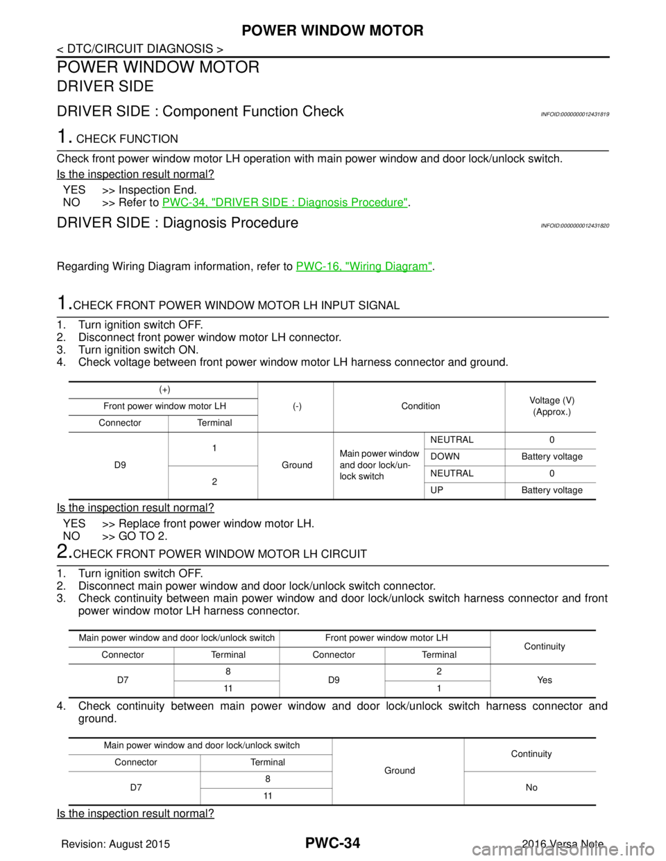
1.CHECK FRONT POWER WINDOW MOTOR LH INPUT SIGNAL
1. Turn ignition switch OFF.
2. Disconnect front power window motor LH connector.
3. Turn ignition switch ON.
4. Check voltage between front power window motor LH harness connector and ground.
Is the inspection result normal?
YES >> Replace front power window motor LH.
NO >> GO TO 2.
2.CHECK FRONT POWER WINDOW MOTOR LH CIRCUIT
1. Turn ignition switch OFF.
2. Disconnect main power window and door lock/unlock switch connector.
3. Check continuity between main power window and door lock/unlock switch harness connector and front power window motor LH harness connector.
4. Check continuity between main power window and door lock/unlock switch harness connector and
ground.
Is the inspection result normal?
(+) (-)Condition Voltage (V)
(Approx.)
Front power window motor LH
Connector Terminal
D9 1
GroundMain power window
and door lock/un-
lock switch NEUTRAL
0
DOWN Battery voltage
2 NEUTRAL
0
UP Battery voltage
Main power window and door lock/unlock switch Front power window motor LH
Continuity
Connector TerminalConnector Terminal
D7 8
D9 2
Ye s
11 1
Main power window and door lock/unlock switch GroundContinuity
Connector Terminal
D7 8
No
11
Revision: August 2015 2016 Versa Note
cardiagn.com
Page 2696 of 3641
POWER WINDOW MOTORPWC-35
< DTC/CIRCUIT DIAGNOSIS >
C
DE
F
G H
I
J
L
M A
B
PWC
N
O P
YES >> Replace main power window and door lock/unlock switch. Refer to PWC-55, "Removal and Instal-
lation".
NO >> Repair or replace harness.
PASSENGER SIDE
PASSENGER SIDE : Comp onent Function CheckINFOID:0000000012431821
1. CHECK FUNCTION
Check front power window motor RH operation with main power window and d\
oor lock/unlock switch or power
window and door lock/unlock switch RH.
Is the inspection result normal?
YES >> Inspection End.
NO >> Refer to PWC-35, "
PASSENGER SIDE : Diagnosis Procedure".
PASSENGER SIDE : Dia gnosis ProcedureINFOID:0000000012431822
Regarding Wiring Diagram information, refer to PWC-16, "Wiring Diagram".
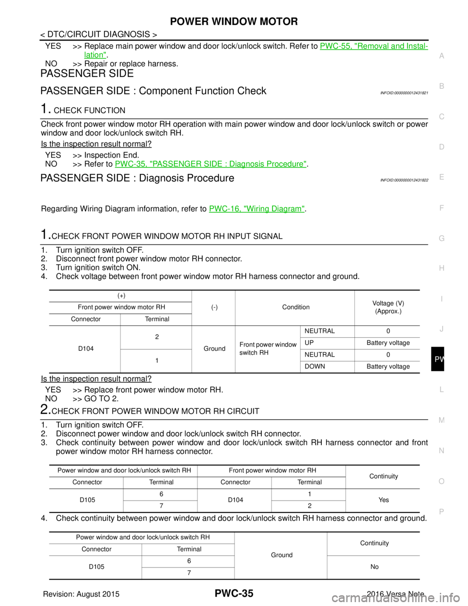
1.CHECK FRONT POWER WINDOW MOTOR RH INPUT SIGNAL
1. Turn ignition switch OFF.
2. Disconnect front power window motor RH connector.
3. Turn ignition switch ON.
4. Check voltage between front power window motor RH harness connector and ground.
Is the inspection result normal?
YES >> Replace front power window motor RH.
NO >> GO TO 2.
2.CHECK FRONT POWER WINDOW MOTOR RH CIRCUIT
1. Turn ignition switch OFF.
2. Disconnect power window and door lock/unlock switch RH connector.
3. Check continuity between power window and door lock/unlock switch RH harness connector and front power window motor RH harness connector.
4. Check continuity between power window and door lock/unlock switch RH harness connector and ground.
(+)
(-)Condition Voltage (V)
(Approx.)
Front power window motor RH
Connector Terminal
D104 2
GroundFront power window
switch RH NEUTRAL
0
UP Battery voltage
1 NEUTRAL
0
DOWN Battery voltage
Power window and door lock/unlock switch RH Front power window motor RH
Continuity
Connector TerminalConnector Terminal
D105 6
D104 1
Ye s
72
Power window and door lock/unlock switch RH GroundContinuity
Connector Terminal
D105 6
No
7
Revision: August 2015 2016 Versa Note
cardiagn.com
Page 2697 of 3641
PWC-36
< DTC/CIRCUIT DIAGNOSIS >
POWER WINDOW MOTOR
Is the inspection result normal?
YES >> Replace power window and door lock/unlock switch RH. Refer to PWC-56, "Removal and Installa-
tion".
NO >> Repair or replace harness.
REAR LH
REAR LH : Componen t Function CheckINFOID:0000000012431823
1.CHECK FUNCTION
Check rear power window motor LH operation with main power window and door lock/unlock switch or rear
power window switch LH.
Is the inspection result normal?
YES >> Inspection End.
NO >> Refer to PWC-36, "
REAR LH : Diagnosis Procedure".
REAR LH : Diagnosis ProcedureINFOID:0000000012431824
Regarding Wiring Diagram information, refer to PWC-16, "Wiring Diagram".
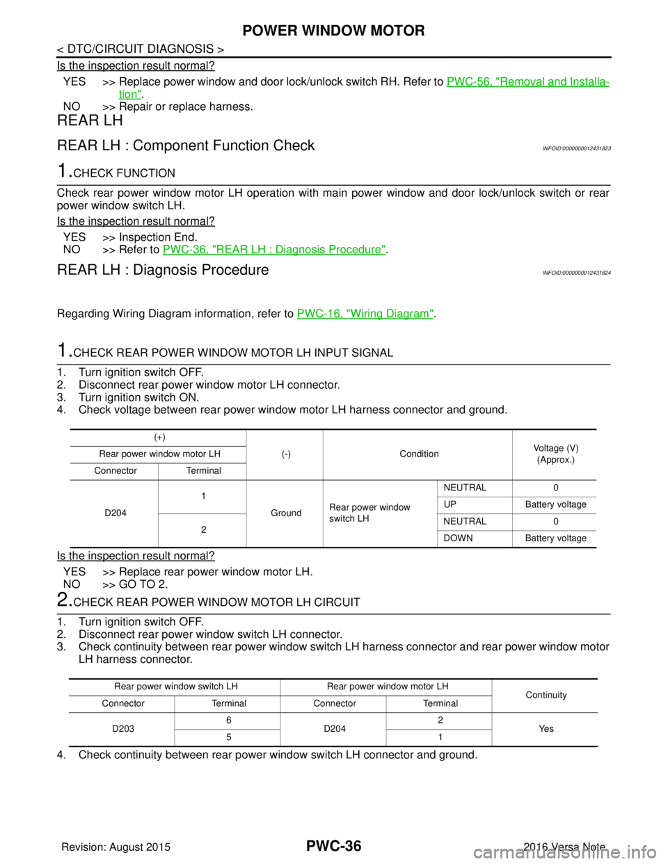
1.CHECK REAR POWER WINDOW MOTOR LH INPUT SIGNAL
1. Turn ignition switch OFF.
2. Disconnect rear power window motor LH connector.
3. Turn ignition switch ON.
4. Check voltage between rear power window motor LH harness connector and ground.
Is the inspection result normal?
YES >> Replace rear power window motor LH.
NO >> GO TO 2.
2.CHECK REAR POWER WINDOW MOTOR LH CIRCUIT
1. Turn ignition switch OFF.
2. Disconnect rear power window switch LH connector.
3. Check continuity between rear power window switch LH harness connector and rear power window motor LH harness connector.
4. Check continuity between rear power window switch LH connector and ground.
(+) (-)Condition Voltage (V)
(Approx.)
Rear power window motor LH
Connector Terminal
D204 1
GroundRear power window
switch LH NEUTRAL
0
UP Battery voltage
2 NEUTRAL
0
DOWN Battery voltage
Rear power window switch LH Rear power window motor LH
Continuity
Connector TerminalConnector Terminal
D203 6
D204 2
Ye s
51
Revision: August 2015 2016 Versa Note
cardiagn.com
Page 2698 of 3641
POWER WINDOW MOTORPWC-37
< DTC/CIRCUIT DIAGNOSIS >
C
DE
F
G H
I
J
L
M A
B
PWC
N
O P
Is the inspection result normal?
YES >> Replace rear power window switch LH. Refer to PWC-57, "Removal and Installation".
NO >> Repair or replace harness.
REAR RH
REAR RH : Component Function CheckINFOID:0000000012431825
1. CHECK FUNCTION
Check rear power window motor RH operation with main power window and door lock/unlock switch or rear
power window switch RH.
Is the inspection result normal?
YES >> Inspection End.
NO >> Refer to PWC-37, "
REAR RH : Diagnosis Procedure".
REAR RH : Diagnosis ProcedureINFOID:0000000012431826
Regarding Wiring Diagram information, refer to PWC-16, "Wiring Diagram".
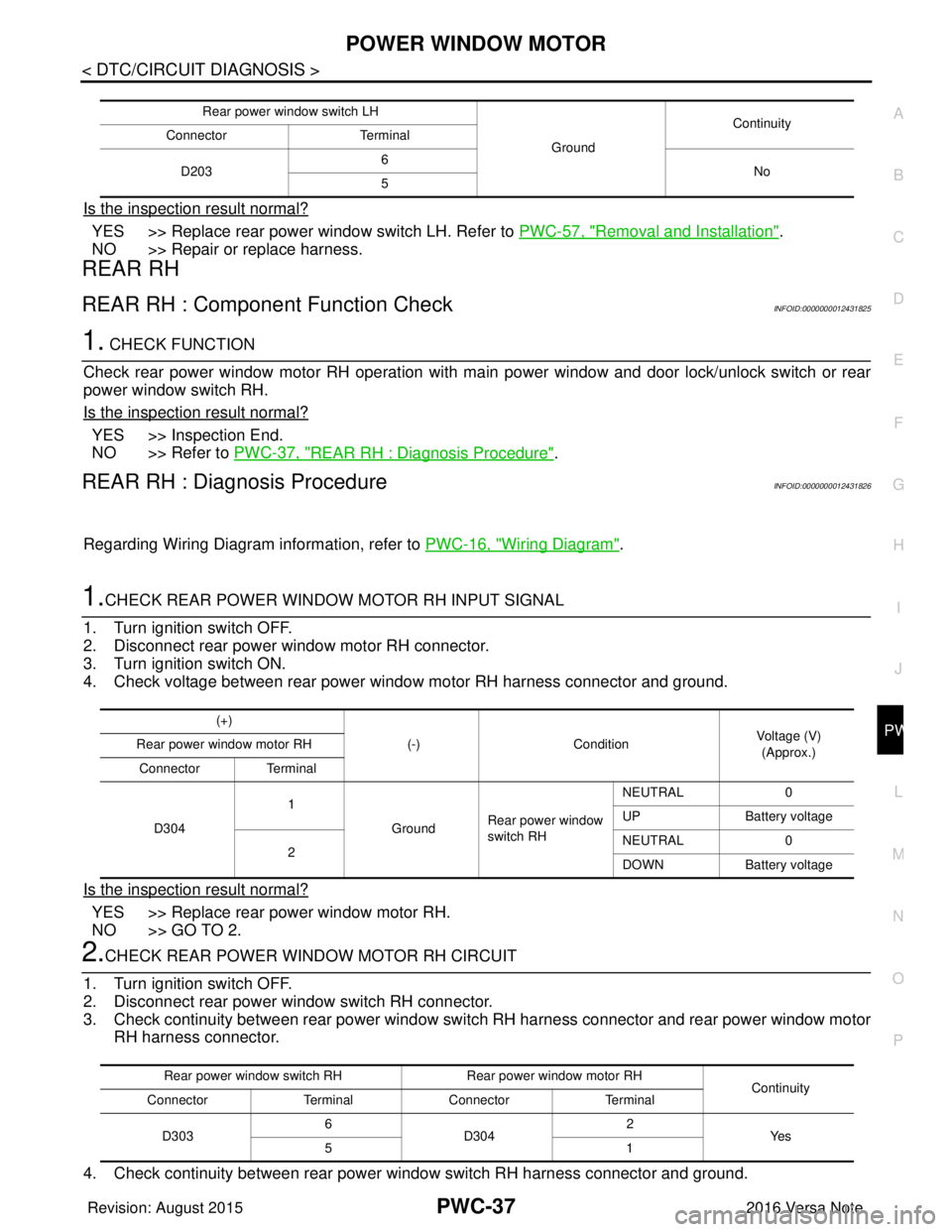
1.CHECK REAR POWER WINDOW MOTOR RH INPUT SIGNAL
1. Turn ignition switch OFF.
2. Disconnect rear power window motor RH connector.
3. Turn ignition switch ON.
4. Check voltage between rear power window motor RH harness connector and ground.
Is the inspection result normal?
YES >> Replace rear power window motor RH.
NO >> GO TO 2.
2.CHECK REAR POWER WINDOW MOTOR RH CIRCUIT
1. Turn ignition switch OFF.
2. Disconnect rear power window switch RH connector.
3. Check continuity between rear power window swit ch RH harness connector and rear power window motor
RH harness connector.
4. Check continuity between rear power window switch RH harness connector and ground.
Rear power window switch LH GroundContinuity
Connector Terminal
D203 6
No
5
(+)
(-)Condition Voltage (V)
(Approx.)
Rear power window motor RH
Connector Terminal
D304 1
GroundRear power window
switch RH NEUTRAL
0
UP Battery voltage
2 NEUTRAL
0
DOWN Battery voltage
Rear power window switch RH Rear power window motor RH
Continuity
Connector TerminalConnector Terminal
D303 6
D304 2
Ye s
51
Revision: August 2015 2016 Versa Note
cardiagn.com
Page 2700 of 3641
DOOR SWITCHPWC-39
< DTC/CIRCUIT DIAGNOSIS >
C
DE
F
G H
I
J
L
M A
B
PWC
N
O P
DOOR SWITCH
WITH INTELLIGENT KEY SYSTEM
WITH INTELLIGENT KEY SYST EM : Component Function CheckINFOID:0000000012431827
1.CHECK FUNCTION
1. Select “DOOR LOCK” of “BCM” using CONSULT.
2. Select “DOOR SW-DR” and “DOOR SW-AS” in “Data Monitor”.
3. Check that the function operates normall y according to the following conditions:
Is the inspection result normal?
YES >> Door switch is OK.
NO >> Refer to PWC-39, "
WITH INTELLIGENT KEY SYSTEM : Diagnosis Procedure".
WITH INTELLIGENT KEY SYST EM : Diagnosis ProcedureINFOID:0000000012431828
Regarding Wiring Diagram information, refer to PWC-16, "Wiring Diagram".
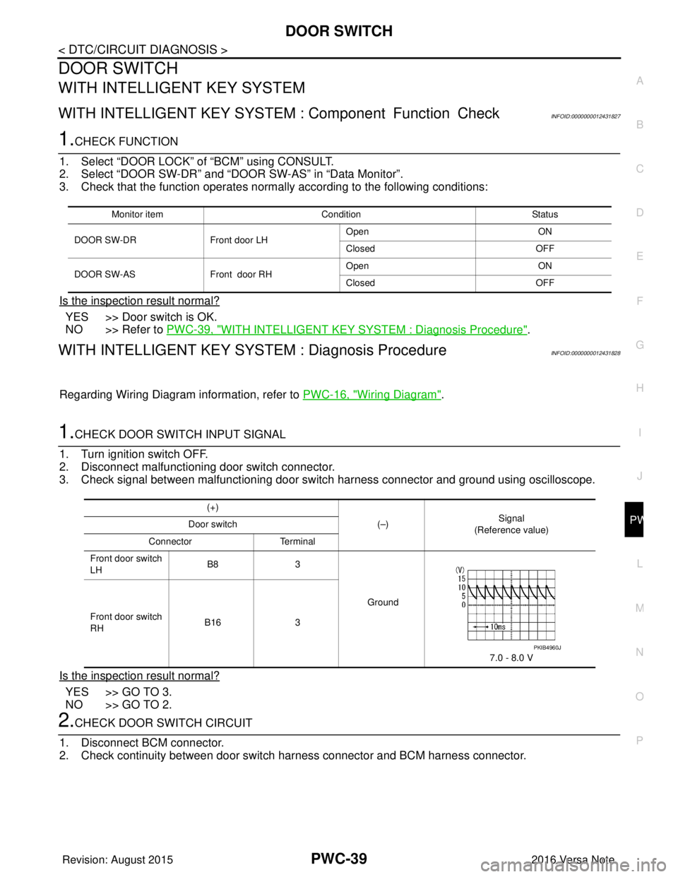
1.CHECK DOOR SWITCH INPUT SIGNAL
1. Turn ignition switch OFF.
2. Disconnect malfunctioning door switch connector.
3. Check signal between malfunctioning door switch harness connector and ground using oscilloscope.
Is the inspection result normal?
YES >> GO TO 3.
NO >> GO TO 2.
2.CHECK DOOR SWITCH CIRCUIT
1. Disconnect BCM connector.
2. Check continuity between door switch harness connector and BCM harness connector.
Monitor item Condition Status
DOOR SW-DR Front door LH Open
ON
Closed OFF
DOOR SW-AS Front door RHOpen
ON
Closed OFF
(+)
(–)Signal
(Reference value)
Door switch
Connector Terminal
Front door switch
LH B8
3
Ground
7.0 - 8.0 V
Front door switch
RH
B16
3
PKIB4960J
Revision: August 2015 2016 Versa Note
cardiagn.com
Page 2702 of 3641
DOOR SWITCHPWC-41
< DTC/CIRCUIT DIAGNOSIS >
C
DE
F
G H
I
J
L
M A
B
PWC
N
O P
With CONSULT
Check door switches “DOOR SW-DR” and “DOOR SW-AS” in “Data Monitor”.
Is the inspection result normal?
YES >> Door switch is OK.
NO >> Refer to PWC-41, "
WITHOUT INTELLIGENT KEY SY STEM : Diagnosis Procedure".
WITHOUT INTELLIGENT KEY SYSTEM : Diagnosis ProcedureINFOID:0000000012431832
Regarding Wiring Diagram information, refer to PWC-16, "Wiring Diagram".
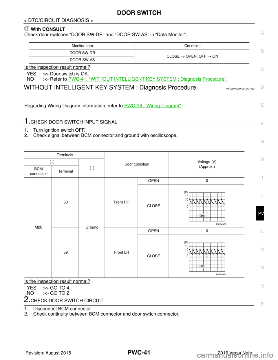
1.CHECK DOOR SWITCH INPUT SIGNAL
1. Turn ignition switch OFF.
2. Check signal between BCM connector and ground with oscilloscope.
Is the inspection result normal?
YES >> GO TO 4.
NO >> GO TO 2.
2.CHECK DOOR SWITCH CIRCUIT
1. Disconnect BCM connector.
2. Check continuity between BCM connector and door switch connector.
Monitor item Condition
DOOR SW-DR CLOSE → OPEN: OFF → ON
DOOR SW-AS
Te r m i n a l s
Door condition Voltage (V)
(Approx.)
(+)
(–)
BCM
connector Te r m i n a l
M20 60
Ground Front RH
OPEN
0
CLOSE
59 Front LHOPEN
0
CLOSE
PKIB4960J
PKIB4960J
Revision: August 2015 2016 Versa Note
cardiagn.com
Page 2720 of 3641
RAX-2
< PRECAUTION >
PRECAUTIONS
PRECAUTION
PRECAUTIONS
Precaution for Supplemental Restraint System (SRS) "AIR BAG" and "SEAT BELT
PRE-TENSIONER"
INFOID:0000000012431904
The Supplemental Restraint System such as “A IR BAG” and “SEAT BELT PRE-TENSIONER”, used along
with a front seat belt, helps to reduce the risk or severity of injury to the driver and front passenger for certain
types of collision. Information necessary to service the system safely is included in the SR and SB section of
this Service Manual.
WARNING:
• To avoid rendering the SRS inopera tive, which could increase the risk of personal injury or death in
the event of a collision which would result in air bag inflation, all maintenance must be performed by
an authorized NISSAN/INFINITI dealer.
• Improper maintenance, including in correct removal and installation of the SRS, can lead to personal
injury caused by unintent ional activation of the system. For re moval of Spiral Cable and Air Bag
Module, see the SR section.
• Do not use electrical test equipmen t on any circuit related to the SRS unless instructed to in this
Service Manual. SRS wiring harn esses can be identified by yellow and/or orange harnesses or har-
ness connectors.
PRECAUTIONS WHEN USING POWER TOOLS (AIR OR ELECTRIC) AND HAMMERS
WARNING:
• When working near the Airbag Diagnosis Sensor Unit or other Airbag System sensors with the Igni-
tion ON or engine running, DO NOT use air or electri c power tools or strike near the sensor(s) with a
hammer. Heavy vibration could activate the sensor( s) and deploy the air bag(s), possibly causing
serious injury.
• When using air or electric power tools or hammers , always switch the Ignition OFF, disconnect the
battery and wait at least three minutes before performing any service.
Precautions for Wheel HubINFOID:0000000012431905
Observe the following precautions when assembling wheel hub.
• Perform work in a location that is free from dust, dirt and debris.
• Use paper shop towels while performing repairs. Fabric shop cloths must not be used because of the danger of lint adhering to parts.
• Do not drop any of the components such as the brake drum, wheel bearing, spindle, or wheel hub lock nut. If
any of these parts have been dropped, they must be replaced.
• Always check that the tools used to press-fit the wheel bearing to the brake drum have no wear and defor-
mation. Damaged tools will not guarantee that pre ssure can be applied vertically and damage parts.
Revision: August 2015 2016 Versa Note
cardiagn.com
Page 2730 of 3641
RSU-2
< PRECAUTION >
PRECAUTIONS
PRECAUTION
PRECAUTIONS
Precaution for Supplemental Restraint System (SRS) "AIR BAG" and "SEAT BELT
PRE-TENSIONER"
INFOID:0000000012431916
The Supplemental Restraint System such as “A IR BAG” and “SEAT BELT PRE-TENSIONER”, used along
with a front seat belt, helps to reduce the risk or severity of injury to the driver and front passenger for certain
types of collision. Information necessary to service the system safely is included in the SR and SB section of
this Service Manual.
WARNING:
• To avoid rendering the SRS inopera tive, which could increase the risk of personal injury or death in
the event of a collision which would result in air bag inflation, all maintenance must be performed by
an authorized NISSAN/INFINITI dealer.
• Improper maintenance, including in correct removal and installation of the SRS, can lead to personal
injury caused by unintent ional activation of the system. For re moval of Spiral Cable and Air Bag
Module, see the SR section.
• Do not use electrical test equipmen t on any circuit related to the SRS unless instructed to in this
Service Manual. SRS wiring harn esses can be identified by yellow and/or orange harnesses or har-
ness connectors.
PRECAUTIONS WHEN USING POWER TOOLS (AIR OR ELECTRIC) AND HAMMERS
WARNING:
• When working near the Airbag Diagnosis Sensor Unit or other Airbag System sensors with the Igni-
tion ON or engine running, DO NOT use air or electri c power tools or strike near the sensor(s) with a
hammer. Heavy vibration could activate the sensor( s) and deploy the air bag(s), possibly causing
serious injury.
• When using air or electric power tools or hammers , always switch the Ignition OFF, disconnect the
battery and wait at least three minutes before performing any service.
Precaution for SuspensionINFOID:0000000012431917
• When installing rubber bushings, the final tightening mu st be carried out under unladen conditions with tires
on ground. Spilled oil might shorten the life of rubber bushings. Be sure to wipe off any spilled oil.
- Unladen conditions mean that fuel, engine coolant and lubricant are full. Spare tire, jack, hand tools and mats are in designated positions.
• After servicing suspension parts, be sure to check wheel alignment.
• Self-lock nuts are not reusable. Always use new ones when installing. Since new self-lock nuts are pre-oiled,
tighten as they are.
• The tightening surface must be kept free of oil/grease.
• When jacking up the vehicle with a floor jack, do not hang the jack on the suspension beam.
Revision: August 2015 2016 Versa Note
cardiagn.com