Page 2682 of 3641
POWER WINDOW SYSTEMPWC-21
< WIRING DIAGRAM >
C
DE
F
G H
I
J
L
M A
B
PWC
N
O P
ABKIA7094GB
Revision: August 2015 2016 Versa Note
cardiagn.com
Page 2683 of 3641
PWC-22
< WIRING DIAGRAM >
POWER WINDOW SYSTEM
AAKIA2296GB
Revision: August 20152016 Versa Note
cardiagn.com
Page 2686 of 3641

POWER SUPPLY AND GROUND CIRCUITPWC-25
< DTC/CIRCUIT DIAGNOSIS >
C
DE
F
G H
I
J
L
M A
B
PWC
N
O P
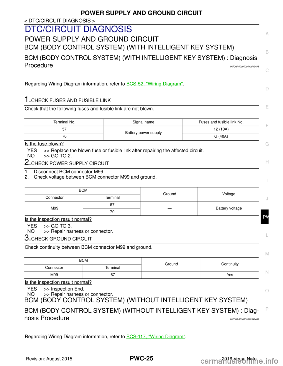
DTC/CIRCUIT DIAGNOSIS
POWER SUPPLY AND GROUND CIRCUIT
BCM (BODY CONTROL SYSTEM) (W ITH INTELLIGENT KEY SYSTEM)
BCM (BODY CONTROL SYSTEM) (WITH IN TELLIGENT KEY SYSTEM) : Diagnosis
Procedure
INFOID:0000000012542488
Regarding Wiring Diagram information, refer to BCS-52, "Wiring Diagram".
1.CHECK FUSES AND FUSIBLE LINK
Check that the following fuses and fusible link are not blown.
Is the fuse blown?
YES >> Replace the blown fuse or fusible link after repairing the affected circuit.
NO >> GO TO 2.
2.CHECK POWER SUPPLY CIRCUIT
1. Disconnect BCM connector M99.
2. Check voltage between BCM connector M99 and ground.
Is the inspection result normal?
YES >> GO TO 3.
NO >> Repair harness or connector.
3.CHECK GROUND CIRCUIT
Check continuity between BCM connector M99 and ground.
Is the inspection result normal?
YES >> Inspection End.
NO >> Repair harness or connector.
BCM (BODY CONTROL SYSTEM) (WIT HOUT INTELLIGENT KEY SYSTEM)
BCM (BODY CONTROL SYSTEM) (WITHOUT INTELLIGENT KEY SYSTEM) : Diag-
nosis Procedure
INFOID:0000000012542489
Regarding Wiring Diagram information, refer to BCS-117, "Wiring Diagram".
Terminal No.Signal nameFuses and fusible link No.
57 Battery power supply 12 (10A)
70 G (40A)
BCM
Ground Voltage
Connector Terminal
M99 57
— Battery voltage
70
BCM GroundContinuity
Connector Terminal
M99 67—Yes
Revision: August 2015 2016 Versa Note
cardiagn.com
Page 2687 of 3641

PWC-26
< DTC/CIRCUIT DIAGNOSIS >
POWER SUPPLY AND GROUND CIRCUIT
1.CHECK FUSES AND FUSIBLE LINK
Check that the following fuses and fusible link are not blown.
Is the fuse blown?
YES >> Replace the blown fuse or fusible link after repairing the affected circuit.
NO >> GO TO 2.
2.CHECK POWER SUPPLY CIRCUIT
1. Turn ignition switch OFF.
2. Disconnect BCM connectors.
3. Check voltage between BCM connector and ground.
Is the inspection result normal?
YES >> GO TO 3.
NO >> Repair harness or connector.
3.CHECK GROUND CIRCUIT
Check continuity between BCM connector and ground.
Is the inspection result normal?
YES >> Inspection End.
NO >> Repair harness or connector.
POWER WINDOW MAIN SWITCH
POWER WINDOW MAIN SWITCH : Diagnosis ProcedureINFOID:0000000012431810
Regarding Wiring Diagram information, refer to PWC-16, "Wiring Diagram".
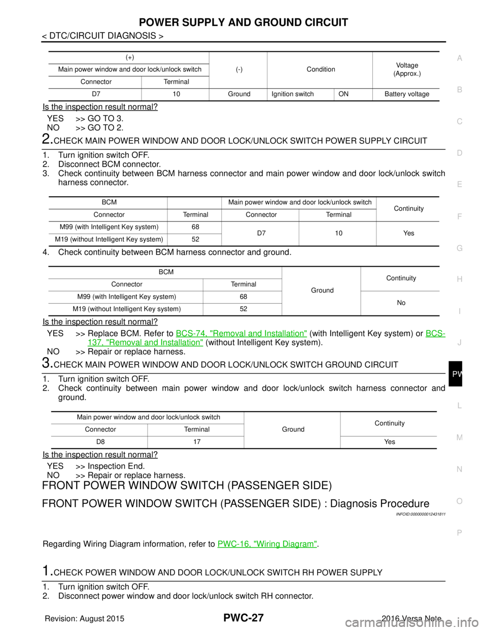
1.CHECK MAIN POWER WINDOW AND DOOR LOCK/UNLOCK SWITCH POWER SUPPLY
1. Turn ignition switch OFF.
2. Disconnect main power window and door lock/unlock switch connector.
3. Check voltage between main power window and door lock/unlock switch harness connector and ground.
Terminal No. Signal nameFuses and fusible link No.
37 Battery power supply 8 (10A)
42 12 (10A)
50 G (40A)
11 Ignition switch ACC or ON 18 (10A)
38 Ignition switch ON or START 2 (10A)
BCMGround Ignition switch position
Connector Terminal
—OFF
ACC ON
M18 11
0 V
Battery voltage
Battery voltage
37
Battery voltage
38 0 V0 V
M19 42
Battery voltage Battery voltage
50
BCM GroundContinuity
Connector Terminal
M19 55—Yes
Revision: August 2015 2016 Versa Note
cardiagn.com
Page 2688 of 3641

POWER SUPPLY AND GROUND CIRCUITPWC-27
< DTC/CIRCUIT DIAGNOSIS >
C
DE
F
G H
I
J
L
M A
B
PWC
N
O P
Is the inspection result normal?
YES >> GO TO 3.
NO >> GO TO 2.
2.CHECK MAIN POWER WINDOW AND DOOR LOCK/UNLOCK SWITCH POWER SUPPLY CIRCUIT
1. Turn ignition switch OFF.
2. Disconnect BCM connector.
3. Check continuity between BCM harness connecto r and main power window and door lock/unlock switch
harness connector.
4. Check continuity between BCM harness connector and ground.
Is the inspection result normal?
YES >> Replace BCM. Refer to BCS-74, "Removal and Installation" (with Intelligent Key system) or BCS-
137, "Removal and Installation" (without Intelligent Key system).
NO >> Repair or replace harness.
3.CHECK MAIN POWER WINDOW AND DOOR LOCK/UNLOCK SWITCH GROUND CIRCUIT
1. Turn ignition switch OFF.
2. Check continuity between main power window and door lock/unlock switch harness connector and ground.
Is the inspection result normal?
YES >> Inspection End.
NO >> Repair or replace harness.
FRONT POWER WINDOW SWIT CH (PASSENGER SIDE)
FRONT POWER WINDOW SWITCH (PASSENG ER SIDE) : Diagnosis Procedure
INFOID:0000000012431811
Regarding Wiring Diagram information, refer to PWC-16, "Wiring Diagram".
1.CHECK POWER WINDOW AND DOOR LOCK/UNLOCK SWITCH RH POWER SUPPLY
1. Turn ignition switch OFF.
2. Disconnect power window and door lock/unlock switch RH connector.
(+)
(-)Condition Vo l ta g e
(Approx.)
Main power window and door lock/unlock switch
Connector Terminal
D7 10Ground Ignition switch ON Battery voltage
BCMMain power window and door lock/unlock switch
Continuity
Connector TerminalConnector Terminal
M99 (with Intelligent Key system) 68 D710Yes
M19 (without Intelligent Key system) 52
BCM GroundContinuity
Connector Terminal
M99 (with Intelligent Key system) 68
No
M19 (without Intelligent Key system) 52
Main power window and door lock/unlock switch
GroundContinuity
Connector Terminal
D8 17 Yes
Revision: August 2015 2016 Versa Note
cardiagn.com
Page 2689 of 3641

PWC-28
< DTC/CIRCUIT DIAGNOSIS >
POWER SUPPLY AND GROUND CIRCUIT
3. Turn ignition switch ON.
4. Check voltage between power window and door lock/unlock switch RH harness connector and ground.
Is the inspection result normal?
YES >> Inspection End.
NO >> GO TO 2.
2.CHECK POWER WINDOWN AND DOOR LOCK/UNLOCK SWITCH RH POWER SUPPLY CIRCUIT
1. Turn ignition switch OFF.
2. Disconnect BCM connector.
3. Check continuity between BCM harness connector and power window and door lock/unlock switch RH harness connector.
4. Check continuity between BCM harness connector and ground.
Is the inspection result normal?
YES >> Replace BCM. Refer to BCS-74, "Removal and Installation" (with Intelligent Key system) or BCS-
137, "Removal and Installation" (without Intelligent Key system).
NO >> Repair or replace harness.
REAR POWER WINDOW SWITCH
REAR POWER WINDOW SW ITCH : Diagnosis ProcedureINFOID:0000000012431812
Regarding Wiring Diagram information, refer to PWC-16, "Wiring Diagram".
1.CHECK REAR POWER WINDOW SWITCH POWER SUPPLY
1. Turn ignition switch OFF.
2. Disconnect rear power window switch connector.
3. Turn ignition switch ON.
4. Check voltage between rear power window switch harness connector and ground.
Is the inspection result normal?
YES >> Inspection End.
(+)
(-)Vo l ta g e
(Approx.)
Power window and door lock/unlock switch RH
Connector Terminal
D105 8GroundBattery voltage
BCM Power window and door lock/unlock switch RH
Continuity
Connector Terminal Connector Terminal
M99 (with Intelligent Key system) 68
D105 8Yes
M19 (without Intelligent Key system) 52
BCM GroundContinuity
Connector Terminal
M99 (with Intelligent Key system) 68
No
M19 (without Intelligent Key system) 52
(+)
(-)Voltage (V)
(Approx.)
Rear power window switch
Connector Terminal
LH D203
4GroundBattery voltage
RH D303
Revision: August 2015 2016 Versa Note
cardiagn.com
Page 2691 of 3641

PWC-30
< DTC/CIRCUIT DIAGNOSIS >
FRONT POWER WINDOW SWITCH (PASSENGER SIDE)
FRONT POWER WINDOW SWITCH (PASSENGER SIDE)
Component Function CheckINFOID:0000000012431813
1. CHECK FUNCTION
Check front power window motor RH operation with power window and door lock/unlock switch RH.
Is the inspection result normal?
YES >> Inspection End.
NO >> Refer to PWC-30, "
Diagnosis Procedure".
Diagnosis ProcedureINFOID:0000000012431814
Regarding Wiring Diagram information, refer to PWC-16, "Wiring Diagram".
1.CHECK POWER WINDOW DOOR LOCK/UNLOCK SWITCH RH INPUT SIGNAL
1. Turn ignition switch OFF.
2. Disconnect power window and door lock/unlock switch RH connector.
3. Turn ignition switch ON.
4. Check voltage between power window and door lock/unlock switch RH harness connector and ground.
Is the inspection result normal?
YES >> GO TO 3.
NO >> GO TO 2.
2.CHECK POWER WINDOW AND DOOR LOCK/UNLOCK SWITCH RH CIRCUIT
1. Turn ignition switch OFF.
2. Disconnect main power window and door lock/unlock switch connector.
3. Check continuity between main power window and door lock/unlock switch harness connector and power window and door lock/unlock switch RH harness connector.
4. Check continuity between main power window and door lock/unlock switch harness connector and
ground.
Is the inspection result normal?
YES >> Replace main power window and door lock/unlock switch. Refer to PWC-55, "Removal and Instal-
lation".
(+)
(-)Condition Voltage (V)
(Approx.)
Power window and door lock/unlock switch RH
Connector Terminal
D105 12
GroundPower window main
switch (front RH) NEUTRAL
0
UP Battery voltage
11 NEUTRAL
0
DOWN Battery voltage
Main power window and door lock/unlock switch Power window and door lock/unlock switch RH
Continuity
Connector TerminalConnector Terminal
D7 12
D105 11
Ye s
16 12
Main power window and door lock/unlock switch GroundContinuity
Connector Terminal
D7 12
No
16
Revision: August 2015 2016 Versa Note
cardiagn.com
Page 2693 of 3641

PWC-32
< DTC/CIRCUIT DIAGNOSIS >
REAR POWER WINDOW SWITCH
REAR POWER WINDOW SWITCH
Component Function CheckINFOID:0000000012431816
1. CHECK FUNCTION
Check rear power window motor operation with rear power window switch.
Is the inspection result normal?
YES >> Inspection End.
NO >> Refer to PWC-32, "
Diagnosis Procedure".
Diagnosis ProcedureINFOID:0000000012431817
Regarding Wiring Diagram information, refer to PWC-16, "Wiring Diagram".
1.CHECK REAR POWER WINDOW SWITCH INPUT SIGNAL
1. Turn ignition switch OFF.
2. Disconnect rear power window switch connector.
3. Turn ignition switch ON.
4. Check voltage between rear power window switch harness connector and ground.
Is the inspection result normal?
YES >> GO TO 3.
NO >> GO TO 2.
2.CHECK REAR POWER WINDOW SWITCH CIRCUIT
1. Turn ignition switch OFF.
2. Disconnect main power window and door lock/unlock switch connector.
3. Check continuity between main power window and door lock/unlock switch harness connector and rear power window switch harness connector.
4. Check continuity between main power window and door lock/unlock switch harness connector and
ground.
(+)
(-)Condition Vo l ta g e
(Approx.)
Rear power window switch
Connector Terminal
LH D203 7
Ground Power window main
switch (rear LH)
NEUTRAL
0
DOWN Battery voltage
8 NEUTRAL
0
UP Battery voltage
RH D303 7
Power window main
switch (rear RH)NEUTRAL
0
DOWN Battery voltage
8 NEUTRAL
0
UP Battery voltage
Main power window and door lock/unlock switch Rear power window switch
Continuity
Connector Terminal ConnectorTerminal
D7 1
LHD203 8
Ye s
37
5
RHD303 7
78
Revision: August 2015 2016 Versa Note
cardiagn.com