2016 NISSAN NOTE turn signal
[x] Cancel search: turn signalPage 3554 of 3641

WCS
SEAT BELT BUCKLE SWITCH SIGNAL CIRCUIT
WCS-39
< DTC/CIRCUIT DIAGNOSIS >
C
D E
F
G H
I
J
K L
M B A
O P
SEAT BELT BUCKLE SW ITCH SIGNAL CIRCUIT
TYPE A
TYPE A : DescriptionINFOID:0000000012432692
Transmits a seat belt buckle switch LH signal to the combination meter.
TYPE A : Component Function CheckINFOID:0000000012432693
1. CHECK COMBINATION METER INPUT SIGNAL
Select “Data Monitor” of “METER/M&A” using “C ONSULT” and check the “BUCKLE SW” monitor value.
Is the inspection result normal?
YES >> Inspection End.
NO >> Refer to WCS-39, "
TYPE A : DiagnosisProcedure".
TYPE A : Diagnosis ProcedureINFOID:0000000012432694
Regarding Wiring Diagram information, refer to WCS-26, "Wiring Diagram".
1.CHECK COMBINATION METER INPUT SIGNAL
1. Turn ignition switch ON.
2. Check voltage between combination meter harness connector M82 terminal 9 and ground.
Is the inspection result normal?
YES >> Replace combination meter. Refer to MWI-54, "Removal and Installation" (Type A).
NO >> GO TO 2.
2.CHECK SEAT BELT BUCKLE SWITCH LH CIRCUIT
1. Turn ignition switch OFF.
2. Disconnect combination meter harness connector M82 and seat belt buckle switch LH harness connector
B13.
3. Check continuity between combination meter har ness connector M82 terminal 9 and seat belt buckle
switch LH harness connector B13 terminal 1.
4. Check continuity between combination meter harness connector M82 terminal 9 and ground.
Is the inspection result normal?
Monitor item Condition Status
BUCKLE SW When seat belt LH is fastened
OFF
When seat belt LH is unfastened ON
Combination meter
GroundCondition Vo l ta g e
(Approx.)
Connector Terminal
M82 9— When seat belt LH is fastened
Battery voltage
When seat belt LH is unfastened 0 V
Combination meterSeat belt buckle switch LH
Continuity
Connector TerminalConnector Terminal
M82 9B13 1Yes
Combination meter GroundContinuity
Connector Terminal
M82 9— No
Revision: August 2015 2016 Versa Note
cardiagn.com
Page 3555 of 3641

WCS-40
< DTC/CIRCUIT DIAGNOSIS >
SEAT BELT BUCKLE SWITCH SIGNAL CIRCUIT
YES >> GO TO 3.
NO >> Repair or replace harness or connector.
3.CHECK SEAT BELT BUCKLE SWITCH LH GROUND CIRCUIT
Check continuity between seat belt buckle swit ch LH harness connector B13 terminal 2 and ground.
Is the inspection result normal?
YES >> Check the seat belt buckle switch LH. Refer to SR-35, "Removal and Installation".
NO >> Repair or replace harness or connector.
TYPE A : Component InspectionINFOID:0000000012432695
1. CHECK SEAT BELT BUCKLE SWITCH LH
1. Turn ignition switch OFF.
2. Disconnect the seat belt buckle switch LH.
3. Check continuity between the seat belt buckle switch LH terminals 1 and 2.
Is the inspection result normal?
YES >> Inspection End.
NO >> Replace the seat belt buckle switch LH. Refer to SR-35, "
Removal and Installation".
TYPE B
TYPE B : DescriptionINFOID:0000000012432696
Transmits a seat belt buckle switch LH signal to the combination meter.
TYPE B : Component Function CheckINFOID:0000000012432697
1. CHECK COMBINATION METER INPUT SIGNAL
Select “Data Monitor” of “METER/M&A” using “C ONSULT” and check the “BUCKLE SW” monitor value.
Is the inspection result normal?
YES >> Inspection End.
NO >> Refer to WCS-40, "
TYPE B : DiagnosisProcedure".
TYPE B : Diagnosis ProcedureINFOID:0000000012432698
Regarding Wiring Diagram information, refer to WCS-26, "Wiring Diagram".
1.CHECK COMBINATION METER INPUT SIGNAL
1. Turn ignition switch ON.
2. Check voltage between combination meter harness connector M24 terminal 9 and ground.
Seat belt buckle switch LH GroundContinuity
Connector Terminal
B13 2—Yes
Terminal ConditionContinuity
12 When seat belt is fastened
No
When seat belt is unfastened Yes
Monitor itemCondition Status
BUCKLE SW When seat belt LH is fastened
OFF
When seat belt LH is unfastened ON
Revision: August 2015 2016 Versa Note
cardiagn.com
Page 3556 of 3641

WCS
SEAT BELT BUCKLE SWITCH SIGNAL CIRCUIT
WCS-41
< DTC/CIRCUIT DIAGNOSIS >
C
D E
F
G H
I
J
K L
M B A
O P
Is the inspection result normal?
YES >> Replace combination meter. Refer to MWI-115, "Removal and Installation" (Type B).
NO >> GO TO 2.
2.CHECK SEAT BELT BUCKLE SWITCH LH CIRCUIT
1. Turn ignition switch OFF.
2. Disconnect combination meter harness connector M24 and seat belt buckle switch LH harness connector
B13.
3. Check continuity between combination meter har ness connector M24 terminal 9 and seat belt buckle
switch LH harness connector B13 terminal 1.
4. Check continuity between combination meter harness connector M24 terminal 9 and ground.
Is the inspection result normal?
YES >> GO TO 3.
NO >> Repair or replace harness or connector.
3.CHECK SEAT BELT BUCKLE SWITCH LH GROUND CIRCUIT
Check continuity between seat belt buckle swit ch LH harness connector B13 terminal 2 and ground.
Is the inspection result normal?
YES >> Check the seat belt buckle switch LH. Refer to SR-35, "Removal and Installation".
NO >> Repair or replace harness or connector.
TYPE B : Component InspectionINFOID:0000000012432699
1. CHECK SEAT BELT BUCKLE SWITCH LH
1. Turn ignition switch OFF.
2. Disconnect the seat belt buckle switch LH.
3. Check continuity between the seat belt buckle switch LH terminals 1 and 2.
Is the inspection result normal?
YES >> Inspection End.
NO >> Replace the seat belt buckle switch LH. Refer to SR-35, "
Removal and Installation".
Combination meter
GroundCondition Vo l ta g e
(Approx.)
Connector Terminal
M24 9— When seat belt LH is fastened
Battery voltage
When seat belt LH is unfastened 0 V
Combination meterSeat belt buckle switch LH
Continuity
Connector TerminalConnector Terminal
M24 9B13 1Yes
Combination meter GroundContinuity
Connector Terminal
M24 9— No
Seat belt buckle switch LH
GroundContinuity
Connector Terminal
B13 2—Yes
Terminal ConditionContinuity
12 When seat belt is fastened
No
When seat belt is unfastened Yes
Revision: August 2015 2016 Versa Note
cardiagn.com
Page 3557 of 3641

WCS-42
< DTC/CIRCUIT DIAGNOSIS >
PARKING BRAKE SWITCH SIGNAL CIRCUIT
PARKING BRAKE SWITCH SIGNAL CIRCUIT
TYPE A
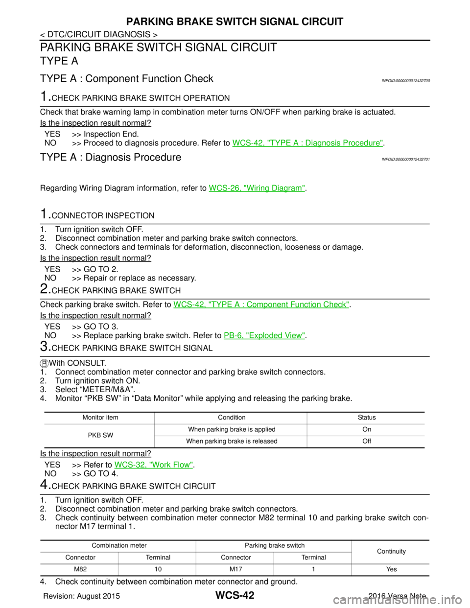
TYPE A : Component Function CheckINFOID:0000000012432700
1.CHECK PARKING BRAKE SWITCH OPERATION
Check that brake warning lamp in combination me ter turns ON/OFF when parking brake is actuated.
Is the inspection result normal?
YES >> Inspection End.
NO >> Proceed to diagnosis procedure. Refer to WCS-42, "
TYPE A : Diagnosis Procedure".
TYPE A : Diagnosis ProcedureINFOID:0000000012432701
Regarding Wiring Diagram information, refer to WCS-26, "Wiring Diagram".
1.CONNECTOR INSPECTION
1. Turn ignition switch OFF.
2. Disconnect combination meter and parking brake switch connectors.
3. Check connectors and terminals for deformation, disconnection, looseness or damage.
Is the inspection result normal?
YES >> GO TO 2.
NO >> Repair or replace as necessary.
2.CHECK PARKING BRAKE SWITCH
Check parking brake switch. Refer to WCS-42, "
TYPE A : Component Function Check".
Is the inspection result normal?
YES >> GO TO 3.
NO >> Replace parking brake switch. Refer to PB-6, "
Exploded View".
3.CHECK PARKING BRAKE SWITCH SIGNAL
With CONSULT.
1. Connect combination meter connector and parking brake switch connectors.
2. Turn ignition switch ON.
3. Select “METER/M&A”.
4. Monitor “PKB SW” in “Data Monitor” while applying and releasing the parking brake.
Is the inspection result normal?
YES >> Refer to WCS-32, "Work Flow".
NO >> GO TO 4.
4.CHECK PARKING BRAKE SWITCH CIRCUIT
1. Turn ignition switch OFF.
2. Disconnect combination meter and parking brake switch connectors.
3. Check continuity between combination meter connec tor M82 terminal 10 and parking brake switch con-
nector M17 terminal 1.
4. Check continuity between combination meter connector and ground.
Monitor item Condition Status
PKB SW When parking brake is applied
On
When parking brake is released Off
Combination meterParking brake switch
Continuity
Connector TerminalConnector Terminal
M82 10 M171Yes
Revision: August 2015 2016 Versa Note
cardiagn.com
Page 3558 of 3641

WCS
PARKING BRAKE SWITCH SIGNAL CIRCUITWCS-43
< DTC/CIRCUIT DIAGNOSIS >
C
DE
F
G H
I
J
K L
M B A
O P
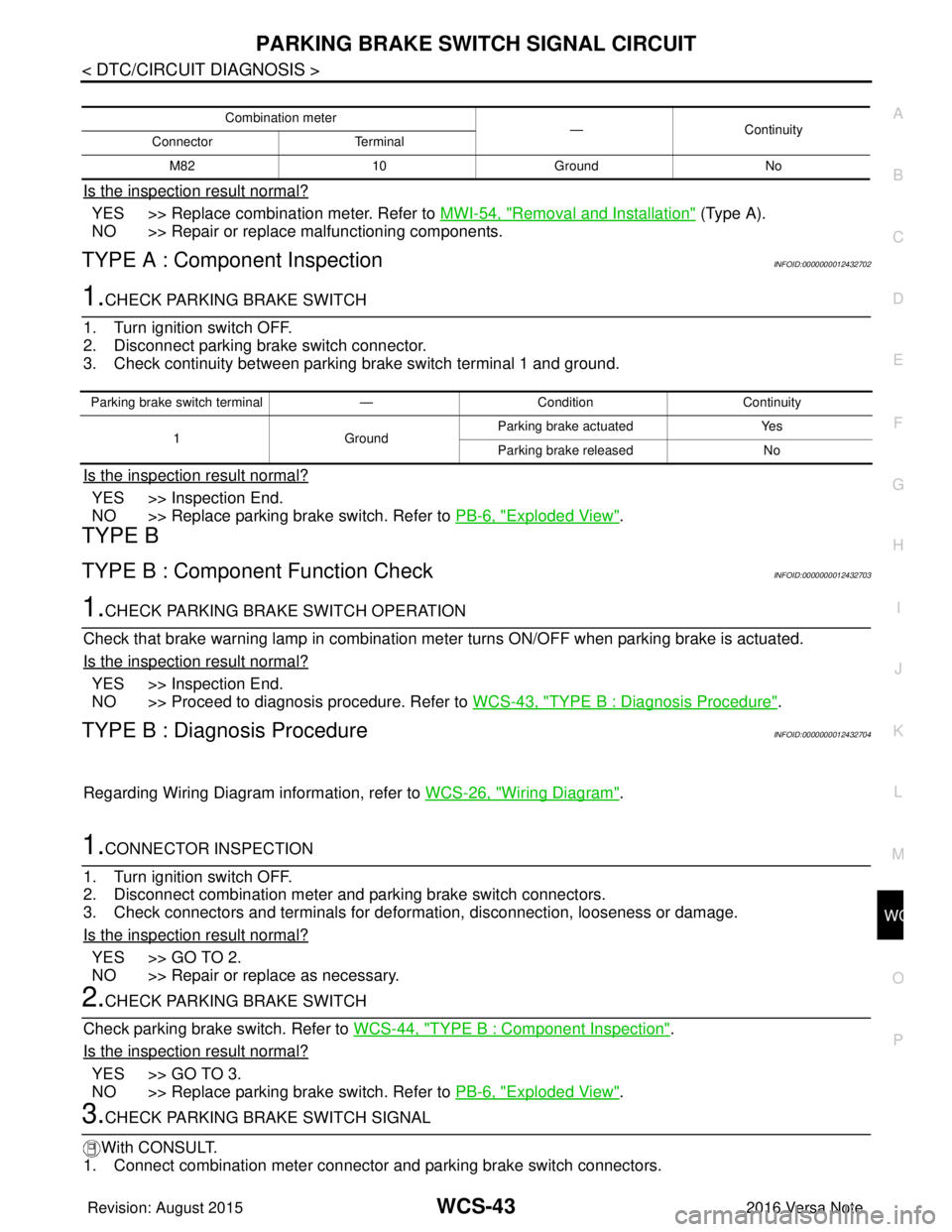
Is the inspection result normal?
YES >> Replace combination meter. Refer to MWI-54, "Removal and Installation" (Type A).
NO >> Repair or replace malfunctioning components.
TYPE A : Component InspectionINFOID:0000000012432702
1.CHECK PARKING BRAKE SWITCH
1. Turn ignition switch OFF.
2. Disconnect parking brake switch connector.
3. Check continuity between parking brake switch terminal 1 and ground.
Is the inspection result normal?
YES >> Inspection End.
NO >> Replace parking brake switch. Refer to PB-6, "
Exploded View".
TYPE B
TYPE B : Component Function CheckINFOID:0000000012432703
1.CHECK PARKING BRA KE SWITCH OPERATION
Check that brake warning lamp in combination meter turns ON/OFF when parking brake is actuated.
Is the inspection result normal?
YES >> Inspection End.
NO >> Proceed to diagnosis procedure. Refer to WCS-43, "
TYPE B : Diagnosis Procedure".
TYPE B : Diagnosis ProcedureINFOID:0000000012432704
Regarding Wiring Diagram information, refer to WCS-26, "Wiring Diagram".
1.CONNECTOR INSPECTION
1. Turn ignition switch OFF.
2. Disconnect combination meter and parking brake switch connectors.
3. Check connectors and terminals for deformation, disconnection, looseness or damage.
Is the inspection result normal?
YES >> GO TO 2.
NO >> Repair or replace as necessary.
2.CHECK PARKING BRAKE SWITCH
Check parking brake switch. Refer to WCS-44, "
TYPE B : Component Inspection".
Is the inspection result normal?
YES >> GO TO 3.
NO >> Replace parking brake switch. Refer to PB-6, "
Exploded View".
3.CHECK PARKING BRAKE SWITCH SIGNAL
With CONSULT.
1. Connect combination meter connector and parking brake switch connectors.
Combination meter —Continuity
Connector Terminal
M82 10 Ground No
Parking brake switch terminal —Condition Continuity
1 GroundParking brake actuated
Yes
Parking brake released No
Revision: August 2015 2016 Versa Note
cardiagn.com
Page 3559 of 3641

WCS-44
< DTC/CIRCUIT DIAGNOSIS >
PARKING BRAKE SWITCH SIGNAL CIRCUIT
2. Turn ignition switch ON.
3. Select “METER/M&A”.
4. Monitor “PKB SW” in “Data Monitor” while applying and releasing the parking brake.
Is the inspection result normal?
YES >> Refer to WCS-32, "Work Flow".
NO >> GO TO 4.
4.CHECK PARKING BRAKE SWITCH CIRCUIT
1. Turn ignition switch OFF.
2. Disconnect combination meter and parking brake switch connectors.
3. Check continuity between combination meter connec tor M24 terminal 10 and parking brake switch con-
nector M17 terminal 1.
4. Check continuity between combination meter connector and ground.
Is the inspection result normal?
YES >> Replace combination meter. Refer to MWI-115, "Removal and Installation" (Type B).
NO >> Repair or replace malfunctioning components.
TYPE B : Component InspectionINFOID:0000000012432705
1.CHECK PARKING BRAKE SWITCH
1. Turn ignition switch OFF.
2. Disconnect parking brake switch connector.
3. Check continuity between parki ng brake switch terminal 1 and ground.
Is the inspection result normal?
YES >> Inspection End.
NO >> Replace parking brake switch. Refer to PB-6, "
Exploded View".
Monitor itemCondition Status
PKB SW When parking brake is applied
ON
When parking brake is released OFF
Combination meterParking brake switch
Continuity
Connector TerminalConnector Terminal
M24 10 M171Yes
Combination meter
—Continuity
Connector Terminal
M24 10 Ground No
Parking brake switch terminal —Condition Continuity
1G ro u nd Parking brake actuated
Yes
Parking brake released No
Revision: August 2015 2016 Versa Note
cardiagn.com
Page 3561 of 3641

WCS-46
< DTC/CIRCUIT DIAGNOSIS >
KEY SWITCH SIGNAL CIRCUIT (WITHOUT INTELLIGENT KEY)
Is the inspection result normal?
YES >> GO TO 4.
NO >> Repair or replace harness.
4. CHECK KEY SWITCH POWER SUPPLY CIRCUIT
Check voltage between key switch harness connector M27 terminal 2 and ground.
Is the inspection result normal?
YES >> Replace key switch.
NO >> Repair or replace harness.
Component InspectionINFOID:0000000012432709
1. CHECK KEY SWITCH
1. Turn ignition switch OFF.
2. Disconnect key switch.
3. Check continuity between key switch terminals 1 and 2.
Is the inspection result normal?
YES >> Inspection End.
NO >> Replace key switch.
BCM
GroundContinuity
Connector Terminal
M18 37 No
Te r m i n a l s
Vo l ta g e
(Approx.)
(+)
(–)
Key switch Terminal
M27 2Ground Battery voltage
Terminal ConditionContinuity
12 When key is removed from key cylinder
No
When key is inserted into key cylinder Yes
Revision: August 2015 2016 Versa Note
cardiagn.com
Page 3573 of 3641

WW-8
< SYSTEM DESCRIPTION >
SYSTEM
SYSTEM
FRONT WIPER AND WASHER SYSTEM
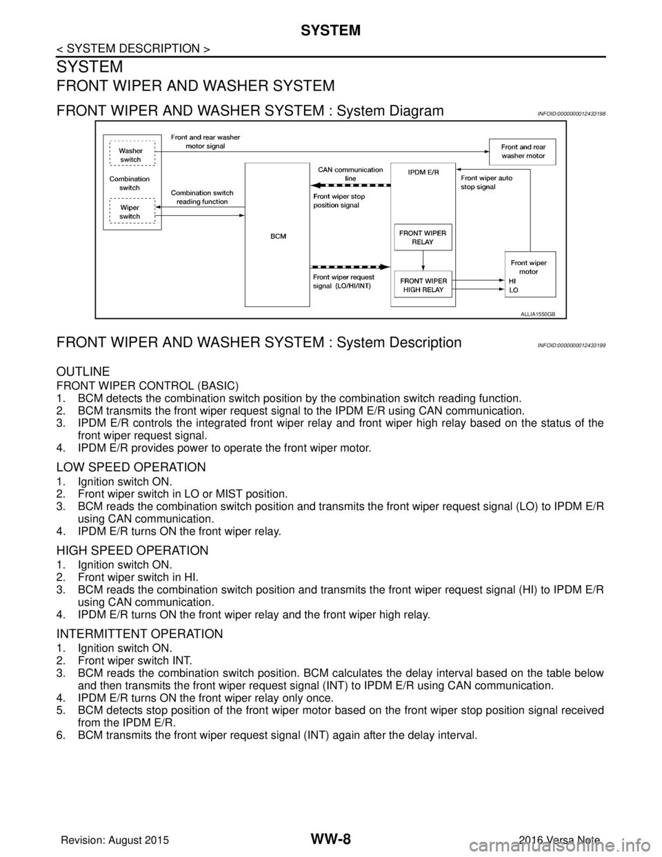
FRONT WIPER AND WASHER SYSTEM : System DiagramINFOID:0000000012433198
FRONT WIPER AND WASHER SYSTEM : System DescriptionINFOID:0000000012433199
OUTLINE
FRONT WIPER CONTROL (BASIC)
1. BCM detects the combination switch position by the combination switch reading function.
2. BCM transmits the front wiper request signal to the IPDM E/R using CAN communication.
3. IPDM E/R controls the integrated front wiper relay and front wiper high relay based on the status of the front wiper request signal.
4. IPDM E/R provides power to operate the front wiper motor.
LOW SPEED OPERATION
1. Ignition switch ON.
2. Front wiper switch in LO or MIST position.
3. BCM reads the combination switch position and transmi ts the front wiper request signal (LO) to IPDM E/R
using CAN communication.
4. IPDM E/R turns ON the front wiper relay.
HIGH SPEED OPERATION
1. Ignition switch ON.
2. Front wiper switch in HI.
3. BCM reads the combination switch position and transmits the front wiper request signal (HI) to IPDM E/R using CAN communication.
4. IPDM E/R turns ON the front wiper relay and the front wiper high relay.
INTERMITTENT OPERATION
1. Ignition switch ON.
2. Front wiper switch INT.
3. BCM reads the combination switch position. BCM ca lculates the delay interval based on the table below
and then transmits the front wiper request signal (INT) to IPDM E/R using CAN communication.
4. IPDM E/R turns ON the front wiper relay only once.
5. BCM detects stop position of the front wiper motor based on the front wiper stop position signal received from the IPDM E/R.
6. BCM transmits the front wiper request si gnal (INT) again after the delay interval.
ALLIA1550GB
Revision: August 2015 2016 Versa Note
cardiagn.com