2016 NISSAN NOTE radiator
[x] Cancel search: radiatorPage 2053 of 3641
HA-28
< REMOVAL AND INSTALLATION >
COOLER PIPE AND HOSE
COOLER PIPE AND HOSE
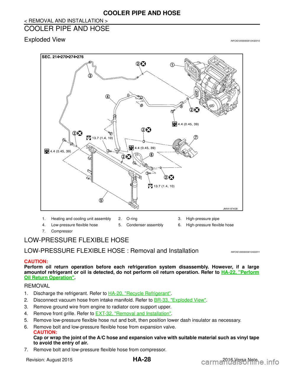
Exploded ViewINFOID:0000000012432010
LOW-PRESSURE FLEXIBLE HOSE
LOW-PRESSURE FLEXIBLE HOSE : Removal and InstallationINFOID:0000000012432011
CAUTION:
Perform oil return operation before each refrigeration system disassembly. However, if a large
amountof refrigerant or oil is detected, do not perform oil return operation. Refer to HA-22, "
Perform
Oil Return Operation".
REMOVAL
1. Discharge the refrigerant. Refer to HA-20, "Recycle Refrigerant".
2. Disconnect vacuum hose from intake manifold. Refer to BR-33, "
Exploded View".
3. Remove ground wire from engine to radiator core support upper.
4. Remove front grille. Refer to EXT-32, "
Removal and Installation".
5. Remove low-pressure flexible hose nut and bolt, then position lower dash insulator as necessary.
6. Remove bolt and low-pressure flexible hose from expansion valve. CAUTION:
Cap or wrap the joint of the A/C hose and expansion valve with suitable material such as vinyl tape
to avoid the entry of air.
7. Remove bolt and low-pressure flexible hose from compressor.
1. Heating and cooling unit assembly 2. O-ring 3. High-pressure pipe
4. Low-pressure flexible hose 5. Condenser assembly 6. High-pressure flexible hose
7. Compressor
JMIIA1874GB
Revision: August 2015 2016 Versa Note
cardiagn.com
Page 2054 of 3641
COOLER PIPE AND HOSEHA-29
< REMOVAL AND INSTALLATION >
C
DE
F
G H
J
K L
M A
B
HA
N
O P
CAUTION:
Cap or wrap the joint of the A/ C hose and compressor with suitable material such as vinyl tape to
avoid the entry of air.
INSTALLATION
Installation is in the reverse order of removal.
CAUTION:
• Do not reuse O-rings.
• Apply compressor oil to new O-rings of low-pressure flexible hose for installation.
• After charging refrigerant, check for leaks. Refer to HA-18, "
Leak Test".
HIGH-PRESSURE FLEXIBLE HOSE
HIGH-PRESSURE FLEXIBLE HOSE : Removal and InstallationINFOID:0000000012432012
CAUTION:
Perform oil return operation before each refrigeration system disassembly. However, if a large
amountof refrigerant or oil is detected, do not perform oil return operation. Refer to HA-22, "
Perform
Oil Return Operation".
REMOVAL
1. Discharge the refrigerant. Refer to HA-20, "Recycle Refrigerant".
2. Remove front grille. Refer to EXT-32, "
Removal and Installation".
3. Remove bolt and high-pressure flexible hose from condenser. CAUTION:
Cap or wrap the joint of the A/C hose and condenser with suitable material such as vinyl tape to
avoid the entry of air.
4. Remove bolt and high-pressure flexible hose from compressor. CAUTION:
Cap or wrap the joint of the A/ C hose and compressor with suitable material such as vinyl tape to
avoid the entry of air.
INSTALLATION
Installation is in the reverse order of removal.
CAUTION:
• Do not reuse O-rings.
• Apply compressor oil to new O-rings of the high-pressure flexible hose for installation.
• After charging refrigerant, check for leaks. Refer to HA-18, "
Leak Test".
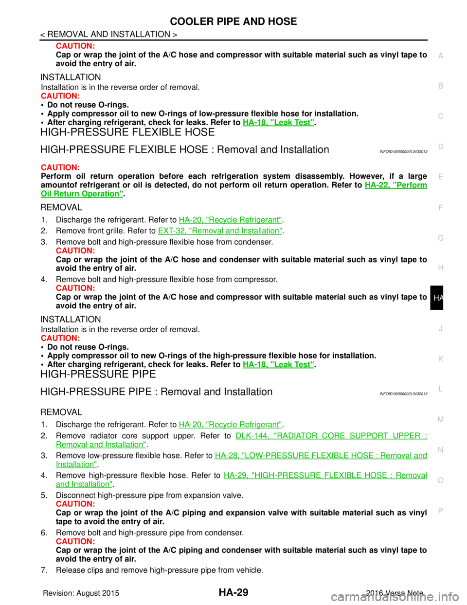
HIGH-PRESSURE PIPE
HIGH-PRESSURE PIPE : Removal and InstallationINFOID:0000000012432013
REMOVAL
1. Discharge the refrigerant. Refer to HA-20, "Recycle Refrigerant".
2. Remove radiator core support upper. Refer to DLK-144, "
RADIATOR CORE SUPPORT UPPER :
Removal and Installation".
3. Remove low-pressure flexible hose. Refer to HA-28, "
LOW-PRESSURE FLEXIBLE HOSE : Removal and
Installation".
4. Remove high-pressure flexible hose. Refer to HA-29, "
HIGH-PRESSURE FLEXIBLE HOSE : Removal
and Installation".
5. Disconnect high-pressure pipe from expansion valve. CAUTION:
Cap or wrap the joint of the A/C piping and expan sion valve with suitable material such as vinyl
tape to avoid the entry of air.
6. Remove bolt and high-pressure pipe from condenser. CAUTION:
Cap or wrap the joint of the A/C piping and conden ser with suitable material such as vinyl tape to
avoid the entry of air.
7. Release clips and remove high-pressure pipe from vehicle.
Revision: August 2015 2016 Versa Note
cardiagn.com
Page 2056 of 3641
CONDENSERHA-31
< REMOVAL AND INSTALLATION >
C
DE
F
G H
J
K L
M A
B
HA
N
O P
CONDENSER
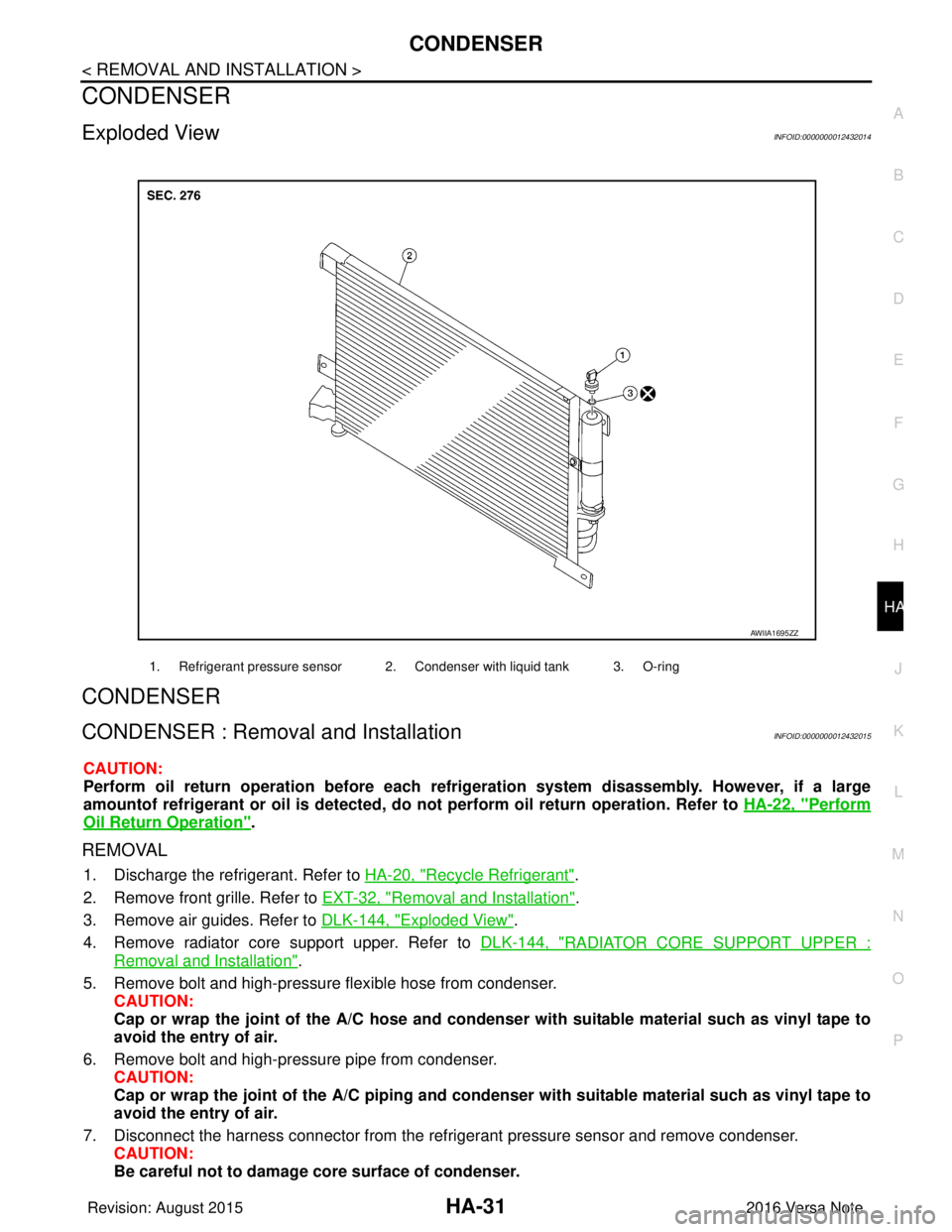
Exploded ViewINFOID:0000000012432014
CONDENSER
CONDENSER : Remova l and InstallationINFOID:0000000012432015
CAUTION:
Perform oil return operation be fore each refrigeration system disassembly. However, if a large
amountof refrigerant or oil is detected, do not perform oil return operation. Refer to HA-22, "
Perform
Oil Return Operation".
REMOVAL
1. Discharge the refrigerant. Refer to HA-20, "Recycle Refrigerant".
2. Remove front grille. Refer to EXT-32, "
Removal and Installation".
3. Remove air guides. Refer to DLK-144, "
Exploded View".
4. Remove radiator core support upper. Refer to DLK-144, "
RADIATOR CORE SUPPORT UPPER :
Removal and Installation".
5. Remove bolt and high-pressure flexible hose from condenser. CAUTION:
Cap or wrap the joint of the A/C hose and condenser with suitable material such as vinyl tape to
avoid the entry of air.
6. Remove bolt and high-pressure pipe from condenser. CAUTION:
Cap or wrap the joint of the A/C piping and conden ser with suitable material such as vinyl tape to
avoid the entry of air.
7. Disconnect the harness connector from the refri gerant pressure sensor and remove condenser.
CAUTION:
Be careful not to damage core surface of condenser.
1. Refrigerant pressure sensor 2. Condenser with liquid tank 3. O-ring
AWIIA1695ZZ
Revision: August 2015 2016 Versa Note
cardiagn.com
Page 2079 of 3641

SQUEAK AND RATTLE TROUBLE DIAGNOSESIP-11
< SYMPTOM DIAGNOSIS >
C
DE
F
G H
I
K L
M A
B
IP
N
O P
1. Loose harness or harness connectors.
2. Front console map/reading lamp lens loose.
3. Loose screws at console attachment points.
SEATS
When isolating seat noise it's important to note the position the seat is in and the load placed on the seat when
the noise is present. These conditions should be duplicated when verifying and isolating the cause of the
noise.
Cause of seat noise include:
1. Headrest rods and holder
2. A squeak between the seat pad cushion and frame
3. The rear seatback lock and bracket
These noises can be isolated by moving or pressing on the suspected components while duplicating the con-
ditions under which the noise occurs. Most of thes e incidents can be repaired by repositioning the component
or applying urethane tape to the contact area.
UNDERHOOD
Some interior noise may be caused by components under the hood or on the engine wall. The noise is then
transmitted into the passenger compartment.
Causes of transmitted underhood noise include:
1. Any component installed to the engine wall
2. Components that pass through the engine wall
3. Engine wall mounts and connectors
4. Loose radiator installation pins
5. Hood bumpers out of adjustment
6. Hood striker out of adjustment
These noises can be difficult to isolate since they cannot be reached from the interior of the vehicle. The best
method is to secure, move or insulate one component at a time and test drive the vehicle. Also, engine rpm or
load can be changed to isolate the noise. Repairs can usually be made by moving, adjusting, securing, or
insulating the component causing the noise.
Revision: August 2015 2016 Versa Note
cardiagn.com
Page 2163 of 3641

INT-12
< SYMPTOM DIAGNOSIS >
SQUEAK AND RATTLE TROUBLE DIAGNOSES
1. Loose harness or harness connectors.
2. Front console map/reading lamp lens loose.
3. Loose screws at console attachment points.
SEATS
When isolating seat noise it's important to note the position the seat is in and the load placed on the seat when
the noise is present. These conditions should be duplicated when verifying and isolating the cause of the
noise.
Cause of seat noise include:
1. Headrest rods and holder
2. A squeak between the seat pad cushion and frame
3. The rear seatback lock and bracket
These noises can be isolated by moving or pressing on the suspected components while duplicating the con-
ditions under which the noise occurs. Most of thes e incidents can be repaired by repositioning the component
or applying urethane tape to the contact area.
UNDERHOOD
Some interior noise may be caused by components under the hood or on the engine wall. The noise is then
transmitted into the passenger compartment.
Causes of transmitted underhood noise include:
1. Any component installed to the engine wall
2. Components that pass through the engine wall
3. Engine wall mounts and connectors
4. Loose radiator installation pins
5. Hood bumpers out of adjustment
6. Hood striker out of adjustment
These noises can be difficult to isolate since they cannot be reached from the interior of the vehicle. The best
method is to secure, move or insulate one component at a time and test drive the vehicle. Also, engine rpm or
load can be changed to isolate the noise. Repairs can usually be made by moving, adjusting, securing, or
insulating the component causing the noise.
Revision: August 2015 2016 Versa Note
cardiagn.com
Page 2321 of 3641

MA-6
< PERIODIC MAINTENANCE >
GENERAL MAINTENANCE
UNDER THE HOOD AND VEHICLE
The maintenance items listed here should be checked periodically (e.g. each time you check the engine oil or refuel).
SeatsCheck seat position controls such as seat adjusters, seatback recliner, etc. to
make sure they operate smoothly and that all latches lock securely in every po-
sition. Check that the head restraints move up and down smoothly and that the
locks (if equipped) hold securely in all latched positions. Check that the latches
lock securely for folding-down rear seatbacks. —
Seat belts Check that all parts of the seat belt system (e.g. buckles, anchors, adjusters and
retractors) operate properly and smoothly and are installed securely. Check the
belt webbing for cuts, fraying, wear or damage. MA-43
Accelerator pedal
Check the pedal for smooth operation and make sure the pedal does not catch
or require uneven effort. Keep the floor mats away from the pedal. —
Brakes Check that the brake does not pull the vehicle to one side when applied. —
Brake pedal and
booster Check the pedal for smooth operation and make sure it has the proper distance
under it when depressed fully. Check the brake booster function. Be sure to keep
floor mats away from the pedal. BR-9
Clutch pedal
Make sure the pedal operates smoothly and check that it has the proper free play. CL-5
Parking brakeCheck that the lever or pedal has the proper travel and make sure that the vehicle
is held securely on a fairly steep hill when only the parking brake is applied. PB-4
CVT "P" (Park) posi-
tion mechanismOn a fairly steep hill check that the vehicle is held securely with the shift selector
in the "P" (PARK) position without applying any brakes.
—
Item
Reference page
Item Reference page
Windshield washer
fluid Check that there is adequate fluid in the tank.
—
Engine coolant level Check the coolant level when the engine is cold. CO-8
Radiator and hosesCheck the front of the radiator and clean off any dirt, insects, leaves, etc., that
may have accumulated. Make sure the radiator hoses have no cracks, deforma-
tion, deterioration or loose connections. CO-12
Brake and clutch fluid
levelsMake sure that the brake and clutch fluid levels are between the “MAX” and “MIN”
lines on the reservoirs. BR-12
CL-7
Battery
Check the fluid level in each cell. It should be between the “MAX” and “MIN” lines.
Vehicles operated in high temperatures or under severe conditions require fre-
quent checks of the battery fluid level. PG-61
Engine drive belts
Make sure that no belt is frayed, worn, cracked or oily. MA-14
Engine oil levelCheck the level on the oil level gauge after parking the vehicle on a level spot and
turning off the engine. MA-20
Exhaust system
Make sure there are no loose supports, cracks or holes. If the sound of the ex-
haust seems unusual or there is a smell of exhaust fumes, immediately locate the
trouble and correct it. MA-26
Underbody
The underbody is frequently exposed to corrosive substances such as those
used on icy roads or to control dust. It is very important to remove these sub-
stances, otherwise rust will form on the floor pan, frame, fuel lines and around the
exhaust system. At the end of winter, the underbody should be thoroughly
flushed with plain water, being careful to clean those areas where mud and dirt
can easily accumulate. —
Fluid leaks Check under the vehicle for fuel, oil, water or other fluid leaks after the vehicle
has been parked for a while. Water dripping from the air conditioner after use is
normal. If you should notice any leaks or gasoline fumes are evident, check for
the cause and correct it immediately. —
Revision: August 2015
2016 Versa Note
cardiagn.com
Page 2327 of 3641
MA-12
< PERIODIC MAINTENANCE >
RECOMMENDED FLUIDS AND LUBRICANTS
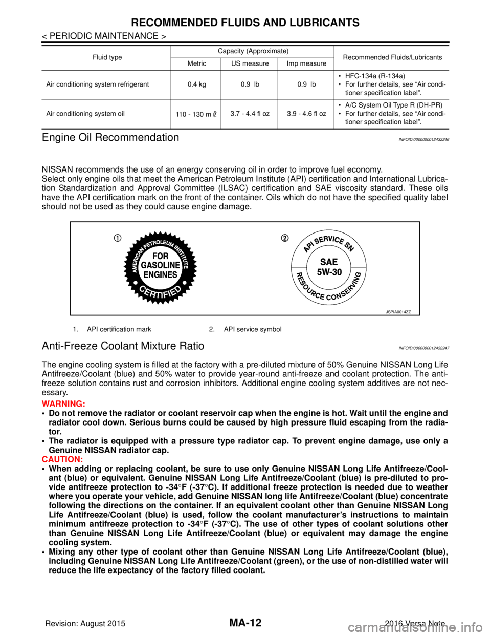
Engine Oil Recommendation
INFOID:0000000012432246
NISSAN recommends the use of an energy conservi ng oil in order to improve fuel economy.
Select only engine oils that meet the American Petroleum Institute (API) certification and International Lubrica-
tion Standardization and Approval Committee (ILSAC) ce rtification and SAE viscosity standard. These oils
have the API certification mark on the front of the container. Oils whic h do not have the specified quality label
should not be used as they could cause engine damage.
Anti-Freeze Coolant Mixture RatioINFOID:0000000012432247
The engine cooling system is filled at the factory with a pre-diluted mixture of 50% Genuine NISSAN Long Life
Antifreeze/Coolant (blue) and 50% water to provide year-round anti-freeze and coolant protection. The anti-
freeze solution contains rust and corrosion inhibitors. Additional engine cooling system additives are not nec-
essary.
WARNING:
• Do not remove the radiator or coolant reservoir cap when the engine is hot. Wait until the engine and radiator cool down. Serious burns could be caused by high pressure fluid escaping from the radia-
tor.
• The radiator is equipped with a pressure type radiator cap. To prevent engine damage, use only a
Genuine NISSAN radiator cap.
CAUTION:
• When adding or replacing coolant, be sure to use only Genuine NISSAN Lo ng Life Antifreeze/Cool-
ant (blue) or equivalent. Genuine NISSAN Long Life Antifreeze/Coolant (blue) is pre-diluted to pro-
vide antifreeze protection to -34 °F (-37 °C). If additional freeze protect ion is needed due to weather
where you operate your vehicle, add Genuine NISSAN long life Antifreeze/Coolant (blue) concentrate
following the directions on the container. If an equivalent coolant other than Genuine NISSAN Long
Life Antifreeze/Coolant (blue) is used, follow the coolant manufact urer’s instructions to maintain
minimum antifreeze protection to -34 °F (-37 °C). The use of other types of coolant solutions other
than Genuine NISSAN Long Life Antifreeze/Coolant (blue) or equivalent may damage the engine
cooling system.
• Mixing any other type of coolant other than Genuine NISSAN Long Life Antifreeze/Coolant (blue),
including Genuine NISSAN Long Life Antifreeze/Coolant (green), or the use of non-distilled water will
reduce the life expectancy of the factory filled coolant.
Air conditioning system refrigerant 0.4 kg0.9 lb 0.9 lb• HFC-134a (R-134a)
• For further details, see “Air condi-
tioner specification label”.
Air conditioning system oil 110 - 130 m3.7 - 4.4 fl oz 3.9 - 4.6 fl oz • A/C System Oil Type R (DH-PR)
• For further details, see “Air condi-
tioner specification label”.
Fluid type
Capacity (Approximate)
Recommended Fluids/Lubricants
Metric US measure Imp measure
1. API certification mark 2. API service symbol
JSPIA0014ZZ
Revision: August 2015 2016 Versa Note
cardiagn.com
Page 2330 of 3641
ENGINE MAINTENANCEMA-15
< PERIODIC MAINTENANCE >
C
DE
F
G H
I
J
K L
M B
MA
N
O A
• When checking immediately after in
stallation, first adjust it to the specified value. Then, after
turning crankshaft two turns or more, readjust to the specified value to avoid variation in deflec-
tion between pulleys.
• When the tension adjustment is performed, the lo ck nut should be in the condition at Step 2. If
the tension adjustment is perfo rmed when the lock nut is loosened more than the temporary
tightening, the idler pulley tilts and the co rrect tension adjustment cannot be performed.
4. Tighten the lock nut to final tightening specification.
ENGINE COOLANT
ENGINE COOLANT : InspectionINFOID:0000000012432252
CHECKING COOLING SYSTEM HOSES
Check hoses for the following:
• Improper attachment
• Leaks
•Cracks
• Damage
• Loose connections
• Chafing
• Deterioration
CHECKING RESERVOIR LEVEL
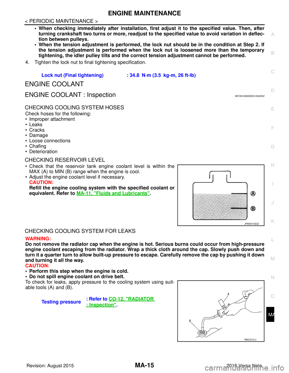
• Check that the reservoir tank engine coolant level is within the MAX (A) to MIN (B) range when the engine is cool.
• Adjust the engine coolant level if necessary. CAUTION:
Refill the engine cooling system with the specified coolant or
equivalent. Refer to MA-11, "
Fluids and Lubricants".
CHECKING COOLING SYSTEM FOR LEAKS
WARNING:
Do not remove the radiator cap when the engine is hot. Serious burns could occur from high-pressure
engine coolant escaping from the radiator. Wrap a thick cloth around the cap. Slowly push down and
turn it a quarter turn to allow built-up pressure to escape. Carefully remove the cap by pushing it down
and turning it all the way.
CAUTION:
• Perform this step when the engine is cold.
• Do not spill engine coolant on drive belt.
To check for leaks, apply pressure to the cooling system using suit-
able tools (A) and (B). Lock nut (Final tightening) :
34.8 N·m (3.5 kg-m, 26 ft-lb)
JPBIA0102ZZ
Testing pressure: Refer to CO-12, "RADIATOR
: Inspection".
PBIC5121J
Revision: August 2015
2016 Versa Note
cardiagn.com