2016 NISSAN NOTE radiator
[x] Cancel search: radiatorPage 1630 of 3641
![NISSAN NOTE 2016 Service Repair Manual SERVICE DATA AND SPECIFICATIONS (SDS)CO-25
< SERVICE DATA AND SPECIFICATIONS (SDS) [HR16DE]
C
D
E
F
G H
I
J
K L
M A
CO
NP
O
SERVICE DATA AND SPECIFICATIONS (SDS)
SERVICE DATA AND SPECIFICATIONS (SDS) NISSAN NOTE 2016 Service Repair Manual SERVICE DATA AND SPECIFICATIONS (SDS)CO-25
< SERVICE DATA AND SPECIFICATIONS (SDS) [HR16DE]
C
D
E
F
G H
I
J
K L
M A
CO
NP
O
SERVICE DATA AND SPECIFICATIONS (SDS)
SERVICE DATA AND SPECIFICATIONS (SDS)](/manual-img/5/57363/w960_57363-1629.png)
SERVICE DATA AND SPECIFICATIONS (SDS)CO-25
< SERVICE DATA AND SPECIFICATIONS (SDS) [HR16DE]
C
D
E
F
G H
I
J
K L
M A
CO
NP
O
SERVICE DATA AND SPECIFICATIONS (SDS)
SERVICE DATA AND SPECIFICATIONS (SDS)
Standard and LimitINFOID:0000000012432150
Engine coolant capa
city (approximate)
Unit: (US qt, Imp qt)
*: Includes reservoir amount.
Radiator
Unit: kPa (kg/cm2, psi)
Thermostat
Standard
Engine coolant capacity (With reservoir tank at “MAX” level)* CVT models
7.3 (7-3/4, 6-3/8)
M/T models 6.7 (7-1/8, 5-7/8)
Reservoir tank engine coolant capacity (At “MAX” level) 0.7 (3/4, 5/8)
Cap relief pressureStandard 88 (0.90, 12.8)
Radiator leak test pressure 156 (1.59, 22.6)
Valve opening temperature 80.5 - 83.5°C (177 - 182 °F)
Maximum valve lift 8.0 mm/95°C (0.315 in/203 °F)
Valve closing temperature 77°C (171 °F)
Revision: August 2015 2016 Versa Note
cardiagn.com
Page 1643 of 3641
![NISSAN NOTE 2016 Service Repair Manual OIL COOLERLU-13
< REMOVAL AND INSTALLATION > [HR16DE]
C
D
E
F
G H
I
J
K L
M A
LU
NP
O
OIL COOLER
Exploded ViewINFOID:0000000012432206
Removal and InstallationINFOID:0000000012432207
REMOVAL
WARNING:
D NISSAN NOTE 2016 Service Repair Manual OIL COOLERLU-13
< REMOVAL AND INSTALLATION > [HR16DE]
C
D
E
F
G H
I
J
K L
M A
LU
NP
O
OIL COOLER
Exploded ViewINFOID:0000000012432206
Removal and InstallationINFOID:0000000012432207
REMOVAL
WARNING:
D](/manual-img/5/57363/w960_57363-1642.png)
OIL COOLERLU-13
< REMOVAL AND INSTALLATION > [HR16DE]
C
D
E
F
G H
I
J
K L
M A
LU
NP
O
OIL COOLER
Exploded ViewINFOID:0000000012432206
Removal and InstallationINFOID:0000000012432207
REMOVAL
WARNING:
Do not remove the radiator cap when the engine is
hot. Serious burns could occur from high-pressure
engine coolant escaping from the radi ator. Wrap a thick cloth around the radiator cap. Slowly turn it a
quarter of a turn to release built-up pressure. Carefu lly remove radiator cap by turning it all the way.
NOTE:
When removing components such as hoses, tubes/lines, etc. , cap or plug openings to prevent fluid from spill-
ing.
1. Drain engine oil. Refer to LU-8, "
Draining".
2. Drain engine coolant. Refer to CO-8, "
Draining Engine Coolant".
3. Remove oil filter. Refer to LU-10, "
Removal and Installation".
4. Remove water hoses from the oil cooler.
5. Remove oil cooler and O-ring. CAUTION:
Do not reuse O-rings.
1. Radiator hose (upper) 2. Hose clamp3. Water hose
4. Radiator hose (lower) 5. Connector bolt6. Oil cooler
7. O-ring 8. Relief valve9. Water hose
A. To radiator (upper side) B. To radiator (lower side)
AWBIA1596ZZ
Revision: August 2015 2016 Versa Note
cardiagn.com
Page 1754 of 3641

EXL-102
< REMOVAL AND INSTALLATION >
FRONT COMBINATION LAMP
REMOVAL AND INSTALLATION
FRONT COMBINATION LAMP
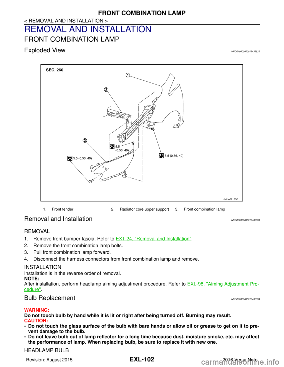
Exploded ViewINFOID:0000000012432832
Removal and InstallationINFOID:0000000012432833
REMOVAL
1. Remove front bumper fascia. Refer to EXT-24, "Removal and Installation".
2. Remove the front combination lamp bolts.
3. Pull front combination lamp forward.
4. Disconnect the harness connectors from front combination lamp and remove.
INSTALLATION
Installation is in the reverse order of removal.
NOTE:
After installation, perform headlamp aiming adjustment procedure. Refer to EXL-98, "
Aiming Adjustment Pro-
cedure".
Bulb ReplacementINFOID:0000000012432834
WARNING:
Do not touch bulb by hand while it is lit or right after being turned off. Burning may result.
CAUTION:
• Do not touch the glass surface of the bulb with bare hands or allow oil or grease to get on it to pre-
vent damage to the bulb.
• Do not leave bulb out of lamp reflector for a long time because dust, moisture smoke, etc. may affect
the performance of lamp. When replacing bulb, be sure to replace it with new one.
HEADLAMP BULB
1. Front fender2. Radiator core upper support 3. Front combination lamp
JMLIA3217GB
Revision: August 2015 2016 Versa Note
cardiagn.com
Page 1787 of 3641

EXT-20
< SYMPTOM DIAGNOSIS >
SQUEAK AND RATTLE TROUBLE DIAGNOSES
1. Loose harness or harness connectors.
2. Front console map/reading lamp lens loose.
3. Loose screws at console attachment points.
SEATS
When isolating seat noise it's important to note the position the seat is in and the load placed on the seat when
the noise is present. These conditions should be duplicated when verifying and isolating the cause of the
noise.
Cause of seat noise include:
1. Headrest rods and holder
2. A squeak between the seat pad cushion and frame
3. The rear seatback lock and bracket
These noises can be isolated by moving or pressing on the suspected components while duplicating the con-
ditions under which the noise occurs. Most of thes e incidents can be repaired by repositioning the component
or applying urethane tape to the contact area.
UNDERHOOD
Some interior noise may be caused by components under the hood or on the engine wall. The noise is then
transmitted into the passenger compartment.
Causes of transmitted underhood noise include:
1. Any component installed to the engine wall
2. Components that pass through the engine wall
3. Engine wall mounts and connectors
4. Loose radiator installation pins
5. Hood bumpers out of adjustment
6. Hood striker out of adjustment
These noises can be difficult to isolate since they cannot be reached from the interior of the vehicle. The best
method is to secure, move or insulate one component at a time and test drive the vehicle. Also, engine rpm or
load can be changed to isolate the noise. Repairs can usually be made by moving, adjusting, securing, or
insulating the component causing the noise.
Revision: August 2015 2016 Versa Note
cardiagn.com
Page 1800 of 3641

ACTIVE GRILLE SHUTTEREXT-33
< REMOVAL AND INSTALLATION >
C
DE
F
G H
I
J
L
M A
B
EXT
N
O P
ACTIVE GRILLE SHUTTER
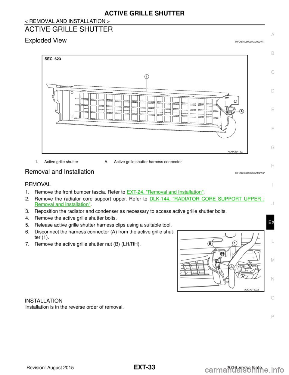
Exploded ViewINFOID:0000000012432171
Removal and InstallationINFOID:0000000012432172
REMOVAL
1. Remove the front bumper fascia. Refer to EXT-24, "Removal and Installation".
2. Remove the radiator core support upper. Refer to DLK-144, "
RADIATOR CORE SUPPORT UPPER :
Removal and Installation".
3. Reposition the radiator and condenser as necessa ry to access active grille shutter bolts.
4. Remove the active grille shutter bolts.
5. Release active grille shutter harness clips using a suitable tool.
6. Disconnect the harness connector (A) from the active grille shut- ter (1).
7. Remove the active grille shutter nut (B) (LH/RH).
INSTALLATION
Installation is in the reverse order of removal.
1. Active grille shutter A. Active grille shutter harness connector
ALKIA3641ZZ
ALKIA3150ZZ
Revision: August 2015 2016 Versa Note
cardiagn.com
Page 1912 of 3641

GI-24
< PRECAUTION >
PRECAUTIONS
General Precautions
INFOID:0000000012433162
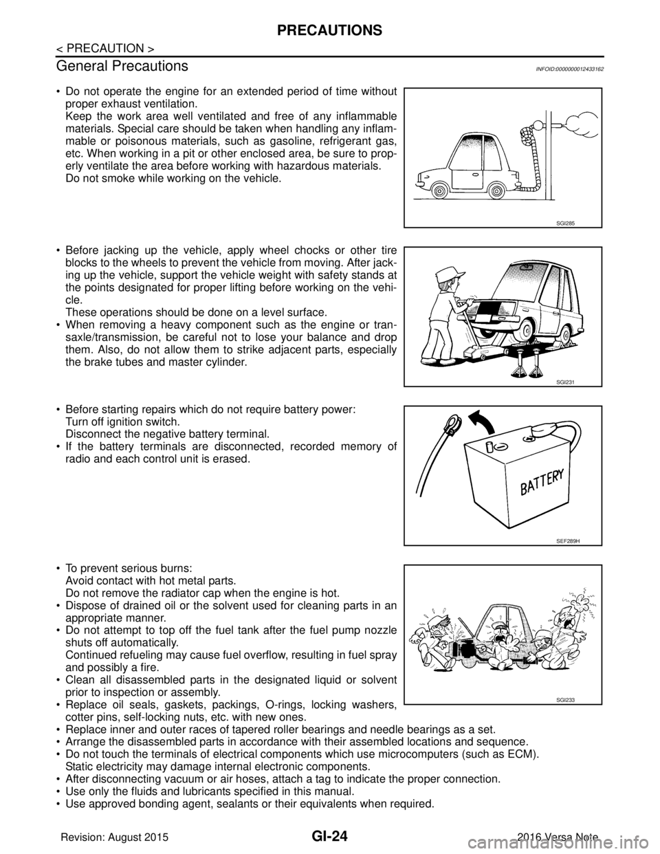
• Do not operate the engine for an extended period of time without proper exhaust ventilation.
Keep the work area well ventilated and free of any inflammable
materials. Special care should be taken when handling any inflam-
mable or poisonous materials, such as gasoline, refrigerant gas,
etc. When working in a pit or other enclosed area, be sure to prop-
erly ventilate the area before working with hazardous materials.
Do not smoke while working on the vehicle.
• Before jacking up the vehicle, apply wheel chocks or other tire blocks to the wheels to prevent the vehicle from moving. After jack-
ing up the vehicle, support the vehicle weight with safety stands at
the points designated for proper lifting before working on the vehi-
cle.
These operations should be done on a level surface.
• When removing a heavy component such as the engine or tran- saxle/transmission, be careful not to lose your balance and drop
them. Also, do not allow them to strike adjacent parts, especially
the brake tubes and master cylinder.
• Before starting repairs which do not require battery power: Turn off ignition switch.
Disconnect the negative battery terminal.
• If the battery terminals are disconnected, recorded memory of radio and each control unit is erased.
• To prevent serious burns: Avoid contact with hot metal parts.
Do not remove the radiator cap when the engine is hot.
• Dispose of drained oil or the solvent used for cleaning parts in an appropriate manner.
• Do not attempt to top off the fuel tank after the fuel pump nozzle
shuts off automatically.
Continued refueling may cause fuel overflow, resulting in fuel spray
and possibly a fire.
• Clean all disassembled parts in the designated liquid or solvent prior to inspection or assembly.
• Replace oil seals, gaskets, packings, O-rings, locking washers,
cotter pins, self-locking nuts, etc. with new ones.
• Replace inner and outer races of tapered roller bearings and needle bearings as a set.
• Arrange the disassembled parts in accordance with their assembled locations and sequence.
• Do not touch the terminals of electrical com ponents which use microcomputers (such as ECM).
Static electricity may damage internal electronic components.
• After disconnecting vacuum or air hoses, atta ch a tag to indicate the proper connection.
• Use only the fluids and lubricants specified in this manual.
• Use approved bonding agent, sealants or their equivalents when required.
SGI285
SGI231
SEF289H
SGI233
Revision: August 2015 2016 Versa Note
cardiagn.com
Page 1948 of 3641

GW-8
< SYMPTOM DIAGNOSIS >
SQUEAK AND RATTLE TROUBLE DIAGNOSES
1. Loose harness or harness connectors.
2. Front console map/reading lamp lens loose.
3. Loose screws at console attachment points.
SEATS
When isolating seat noise it's important to note the position the seat is in and the load placed on the seat when
the noise is present. These conditions should be duplicated when verifying and isolating the cause of the
noise.
Cause of seat noise include:
1. Headrest rods and holder
2. A squeak between the seat pad cushion and frame
3. The rear seatback lock and bracket
These noises can be isolated by moving or pressing on the suspected components while duplicating the con-
ditions under which the noise occurs. Most of thes e incidents can be repaired by repositioning the component
or applying urethane tape to the contact area.
UNDERHOOD
Some interior noise may be caused by components under the hood or on the engine wall. The noise is then
transmitted into the passenger compartment.
Causes of transmitted underhood noise include:
1. Any component installed to the engine wall
2. Components that pass through the engine wall
3. Engine wall mounts and connectors
4. Loose radiator installation pins
5. Hood bumpers out of adjustment
6. Hood striker out of adjustment
These noises can be difficult to isolate since they cannot be reached from the interior of the vehicle. The best
method is to secure, move or insulate one component at a time and test drive the vehicle. Also, engine rpm or
load can be changed to isolate the noise. Repairs can usually be made by moving, adjusting, securing, or
insulating the component causing the noise.
Revision: August 2015 2016 Versa Note
cardiagn.com
Page 2017 of 3641
![NISSAN NOTE 2016 Service Repair Manual INSUFFICIENT HEATINGHAC-49
< SYMPTOM DIAGNOSIS > [MANUAL AIR CONDITIONING]
C
D
E
F
G H
J
K L
M A
B
HAC
N
O P
INSUFFICIENT HEATING
DescriptionINFOID:0000000012430752
Symptom
• Insufficient heating
� NISSAN NOTE 2016 Service Repair Manual INSUFFICIENT HEATINGHAC-49
< SYMPTOM DIAGNOSIS > [MANUAL AIR CONDITIONING]
C
D
E
F
G H
J
K L
M A
B
HAC
N
O P
INSUFFICIENT HEATING
DescriptionINFOID:0000000012430752
Symptom
• Insufficient heating
�](/manual-img/5/57363/w960_57363-2016.png)
INSUFFICIENT HEATINGHAC-49
< SYMPTOM DIAGNOSIS > [MANUAL AIR CONDITIONING]
C
D
E
F
G H
J
K L
M A
B
HAC
N
O P
INSUFFICIENT HEATING
DescriptionINFOID:0000000012430752
Symptom
• Insufficient heating
• No warm air comes out. (Air flow volume is normal.)
Diagnosis ProcedureINFOID:0000000012430753
NOTE:
Perform self-diagnosis with CONSULT before performing sy mptom diagnosis. If any malfunction result or DTC
is detected, perform the corresponding diagnosis.
1.CHECK COOLING SYSTEM
1. Check engine coolant level and check for leakage. Refer to CO-8, "
Inspection".
2. Check radiator cap. Refer to CO-12, "
RADIATOR CAP : Inspection".
3. Check water flow sounds of the engine coolant. Refer to CO-9, "
Refilling".
Is the inspection result normal?
YES >> GO TO 2.
NO >> Refill engine coolant and repair or replace the parts depending on the inspection results.
2.CHECK HEATER HOSE
Check installation of heater hose by visually or touching.
Is the inspection result normal?
YES >> GO TO 3.
NO >> Repair or replace parts depending on the inspection results.
3.CHECK HEATER CORE
1. Check temperature of inlet hose and outlet hose of heater core.
2. Check that inlet side of heater core is hot and the outle t side is slightly lower than/almost equal to the inlet
side.
CAUTION:
Always perform the temperature inspection in a sh ort period of time because the engine coolant
temperature is very hot.
Is the inspection result normal?
YES >> GO TO 4.
NO >> Replace heater core. Refer to HA-35, "
HEATER CORE : Removal and Installation".
4.CHECK AIR LEAKAGE FROM EACH DUCT
Check duct and nozzle, etc. of air conditioning system for air leakage.
Is the inspection result normal?
YES >> Check air mix door cable inst allation and air mix door operation.
NO >> Repair or replace parts depending on the inspection results.
Revision: August 2015 2016 Versa Note
cardiagn.com