2016 NISSAN NOTE check engine
[x] Cancel search: check enginePage 3200 of 3641

STC-16
< BASIC INSPECTION >
DIAGNOSIS AND REPAIR WORKFLOW
YES >> GO TO 7.
NO >> Check harness and connectors based on the information obtained by interview. Refer to GI-42,
"Intermittent Incident".
7.FINAL CHECK
With CONSULT
1. Check the reference value for EPS control unit.
2. Recheck the symptom and check that sympto m is not reproduced on the same conditions.
Is the symptom reproduced?
YES >> GO TO 3.
NO >> Inspection End.
Diagnostic Work SheetINFOID:0000000012431952
Description
• In general, customers have their own criteria for a pr oblem. Therefore, it is important to understand the
symptom and status well enough by asking the customer about his/her concerns carefully. To systemize all
the information for the diagnosis, prepare the interview sheet referring to the interview points.
• In some cases, multiple conditions that appear simultaneously may cause a DTC to be detected.
Interview sheet sample
Interview sheet
Customer
name MR/MSRegistration
number
Initial year
registration
Vehicle type VIN
Storage date EngineMileagekm (Mile)
Symptom �†
The steering wheel position (center) is in the wrong position.
�† Warning lamp turns on.
�† Noise �†Vibration
�† Others
( )
First occurrence �†Recently �†Others ( )
Frequency of occurrence �†Always �†Under a certain conditions of �†Sometimes (time(s)/day)
Climate con-
ditions �†
Irrelevant
Weather �†Fine �†Cloud �†Rain �†Snow �†Others ( )
Temperature �†Hot �†Warm �†Cool �†Cold �†Temperature [Approx. °C ( °F)]
Relative humidity �†High �†Moderate �†Low
Road conditions �†
Urban area �†Suburb area �†High way
�† Mountain road (uphill or down hill) �†Rough road
Operation conditions, etc. �†
Irrelevant
�† When engine starts �†During idling
�† During driving �†During acceleration �†At constant speed driving
�† During deceleration �†During cornerin g (right curve or left curve)
�† During steering
Revision: August 2015 2016 Versa Note
cardiagn.com
Page 3203 of 3641
C1601 BATTERY POWER SUPPLYSTC-19
< DTC/CIRCUIT DIAGNOSIS >
C
DE
F
H I
J
K L
M A
B
STC
N
O P
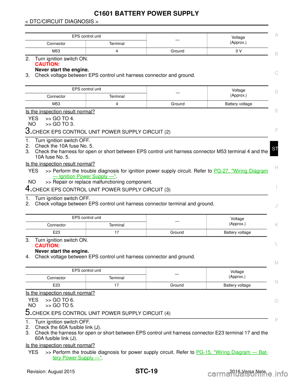
2. Turn ignition switch ON. CAUTION:
Never start the engine.
3. Check voltage between EPS control unit harness connector and ground.
Is the inspection result normal?
YES >> GO TO 4.
NO >> GO TO 3.
3.CHECK EPS CONTROL UNIT POWER SUPPLY CIRCUIT (2)
1. Turn ignition switch OFF.
2. Check the 10A fuse No. 5.
3. Check the harness for open or short between EPS c ontrol unit harness connector M53 terminal 4 and the
10A fuse No. 5.
Is the inspection result normal?
YES >> Perform the trouble diagnosis for i gnition power supply circuit. Refer to PG-27, "Wiring Diagram
— Ignition Power Supply —".
NO >> Repair or replace malfunctioning component.
4.CHECK EPS CONTROL UNIT POWER SUPPLY CIRCUIT (3)
1. Turn ignition switch OFF.
2. Check voltage between EPS control unit harness connector terminal and ground.
3. Turn ignition switch ON. CAUTION:
Never start the engine.
4. Check voltage between EPS control unit harness connector and ground.
Is the inspection result normal?
YES >> GO TO 6.
NO >> GO TO 5.
5.CHECK EPS CONTROL UNIT POWER SUPPLY CIRCUIT (4)
1. Turn ignition switch OFF.
2. Check the 60A fusible link (J).
3. Check the harness for open or short between EPS c ontrol unit harness connector E23 terminal 17 and the
60A fusible link (J).
Is the inspection result normal?
YES >> Perform the trouble diagnosis fo r power supply circuit. Refer to PG-15, "Wiring Diagram — Bat-
tery Power Supply —".
EPS control unit
—Vol tag e
(Approx.)
Connector Terminal
M53 4Ground 0 V
EPS control unit
—Voltage
(Approx.)
Connector Terminal
M53 4GroundBattery voltage
EPS control unit
—Vo l ta g e
(Approx.)
Connector Terminal
E23 17GroundBattery voltage
EPS control unit —Vol tag e
(Approx.)
Connector Terminal
E23 17GroundBattery voltage
Revision: August 2015 2016 Versa Note
cardiagn.com
Page 3205 of 3641
C1604 TORQUE SENSORSTC-21
< DTC/CIRCUIT DIAGNOSIS >
C
DE
F
H I
J
K L
M A
B
STC
N
O P
C1604 TORQUE SENSOR
DTC LogicINFOID:0000000012431955
DTC DETECTION LOGIC
DTC CONFIRMATION PROCEDURE
1.PRECONDITIONING
If “DTC CONFIRMATION PROCEDURE” has been previously conducted, always turn ignition switch OFF and
wait at least 10 seconds before conducting the next test.
>> GO TO 2.
2.DTC REPRODUCTION PROCEDURE
With CONSULT
1. Turn the ignition switch OFF to ON.
2. Perform “Self Diagnostic Result” of “EPS”.
Is DTC
“C1604” detected?
YES >> Proceed to diagnosis procedure. Refer to STC-21, "Diagnosis Procedure".
NO >> Inspection End.
Diagnosis ProcedureINFOID:0000000012431956
Regarding Wiring Diagram information, refer to STC-11, "Wiring Diagram".
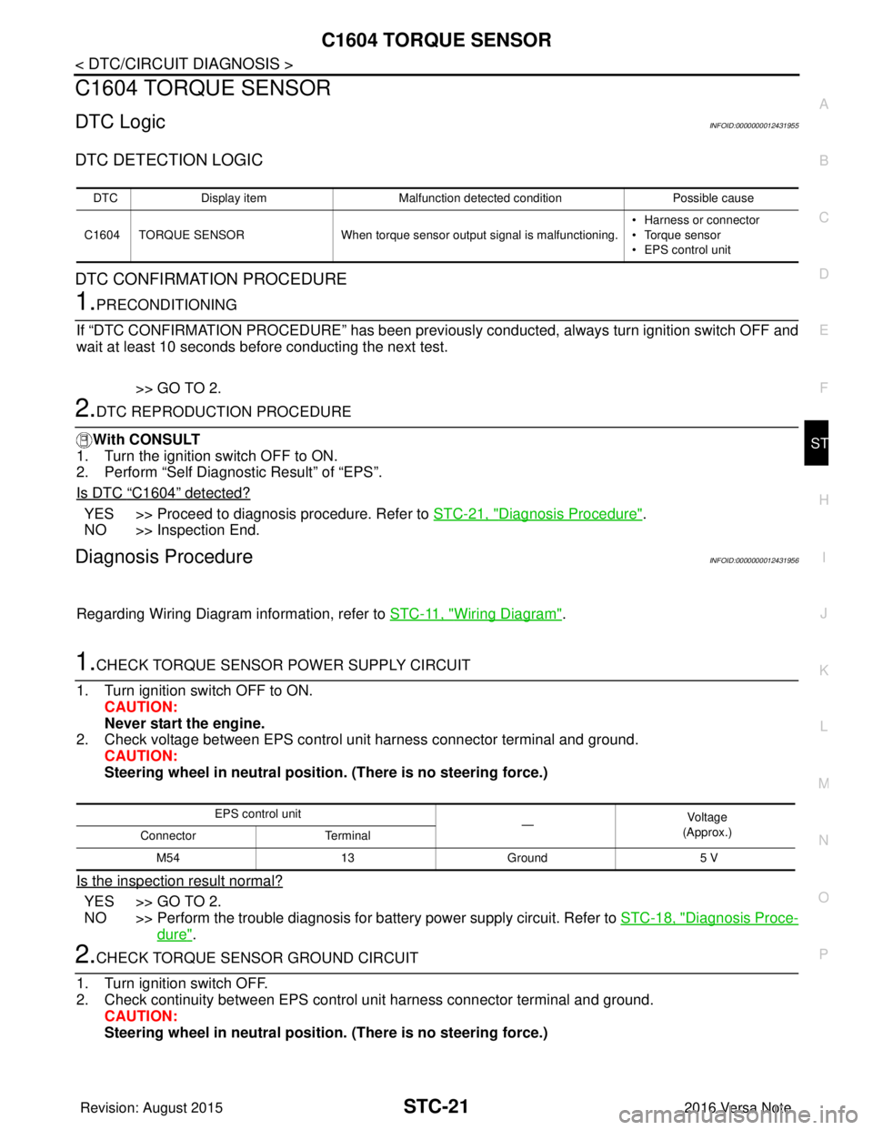
1.CHECK TORQUE SENSOR POWER SUPPLY CIRCUIT
1. Turn ignition switch OFF to ON. CAUTION:
Never start the engine.
2. Check voltage between EPS control unit harness connector terminal and ground.
CAUTION:
Steering wheel in neutral position . (There is no steering force.)
Is the inspection result normal?
YES >> GO TO 2.
NO >> Perform the trouble diagnosis for battery power supply circuit. Refer to STC-18, "
Diagnosis Proce-
dure".
2.CHECK TORQUE SENSOR GROUND CIRCUIT
1. Turn ignition switch OFF.
2. Check continuity between EPS control unit harness connector terminal and ground. CAUTION:
Steering wheel in neutral position . (There is no steering force.)
DTCDisplay item Malfunction detected condition Possible cause
C1604 TORQUE SENSOR When torque sensor output signal is malfunctioning. • Harness or connector
• Torque sensor
• EPS control unit
EPS control unit
—Vo l ta g e
(Approx.)
Connector Terminal
M54 13Ground 5 V
Revision: August 2015 2016 Versa Note
cardiagn.com
Page 3206 of 3641

STC-22
< DTC/CIRCUIT DIAGNOSIS >
C1604 TORQUE SENSOR
Is the inspection result normal?
YES >> GO TO 3.
NO >> Repair open circuit or short to ground or short to power in harness or connectors.
3.CHECK TORQUE SENSOR SIGNAL
1. Turn ignition switch OFF to ON.
2. Check voltage between EPS control unit harness connector terminal and ground. CAUTION:
Steering wheel in neutral position. (There is no steering force.)
3. Start the engine.
4. Check voltage between EPS control unit harness connector terminal and ground while turning the steer- ing wheel.
Is the inspection result normal?
YES >> GO TO 4.
NO >> Torque sensor is malfunctioning. Repl ace steering column assembly. Refer to ST-9, "
Exploded
View".
4.CHECK CONNECTOR
1. Turn ignition switch OFF.
2. Disconnect EPS control unit harness connector.
3. Check terminal for deformation, disconnection, looseness, and so on. If any malfunction is found, repair or replace terminal.
Is the inspection result normal?
YES >> Replace EPS control unit. Refer to STC-37, "Removal and Installation".
NO >> Repair or replace malfunctioning component.
EPS control unit —Continuity
Connector Terminal
M54 15Ground Yes
EPS control unit
—Vo l ta g e
(Approx.)
Connector Terminal
M54 16
Ground 2.5 V
14
EPS control unit —Voltag e
(Approx.)
Connector Terminal
M54 16
Ground 1.6 V – 3.4 V
(The value is changed according to steering left or right)
14
Revision: August 2015
2016 Versa Note
cardiagn.com
Page 3211 of 3641
C1610 ENGINE STATUS SIGNALSTC-27
< DTC/CIRCUIT DIAGNOSIS >
C
DE
F
H I
J
K L
M A
B
STC
N
O P
C1610 ENGINE STATUS SIGNAL
DescriptionINFOID:0000000012431965
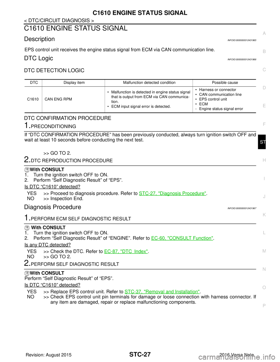
EPS control unit receives the engine status signal from ECM via CAN communication line.
DTC LogicINFOID:0000000012431966
DTC DETECTION LOGIC
DTC CONFIRMATION PROCEDURE
1.PRECONDITIONING
If “DTC CONFIRMATION PROCEDURE” has been previously conducted, always turn ignition switch OFF and
wait at least 10 seconds before conducting the next test.
>> GO TO 2.
2.DTC REPRODUCTION PROCEDURE
With CONSULT
1. Turn the ignition switch OFF to ON.
2. Perform “Self Diagnostic Result” of “EPS”.
Is DTC
“C1610” detected?
YES >> Proceed to diagnosis procedure. Refer to STC-27, "Diagnosis Procedure".
NO >> Inspection End.
Diagnosis ProcedureINFOID:0000000012431967
1.PERFORM ECM SELF DIAGNOSTIC RESULT
With CONSULT
1. Turn the ignition switch OFF to ON.
2. Perform “Self Diagnostic Result” of “ENGINE”. Refer to EC-60, "
CONSULT Function".
Is any DTC detected?
YES >> Check the DTC. Refer to EC-87, "DTCIndex".
NO >> GO TO 2.
2.PERFORM SELF DIAGNOSTIC RESULT
With CONSULT
Perform “Self Diagnostic Result” of “EPS”.
Is DTC
“C1610” detected?
YES >> Replace EPS control unit. Refer to STC-37, "Removal and Installation".
NO >> Check EPS control unit pin terminals for damage or loose connection with harness connector. If
any item are damaged, repair or replace malfunctioning components.
DTC Display item Malfunction detected condition Possible cause
C1610 CAN ENG RPM • Malfunction is detected in engine status signal
that is output from ECM via CAN communica-
tion.
• ECM input signal error is detected. • Harness or connector
• CAN communication line
• EPS control unit
•ECM
- Engine status signal error
Revision: August 2015
2016 Versa Note
cardiagn.com
Page 3213 of 3641
EPS WARNING LAMPSTC-29
< DTC/CIRCUIT DIAGNOSIS >
C
DE
F
H I
J
K L
M A
B
STC
N
O P
EPS WARNING LAMP
Component Function CheckINFOID:0000000012431971
1.CHECK THE ILLUMINATION OF THE EPS WARNING LAMP
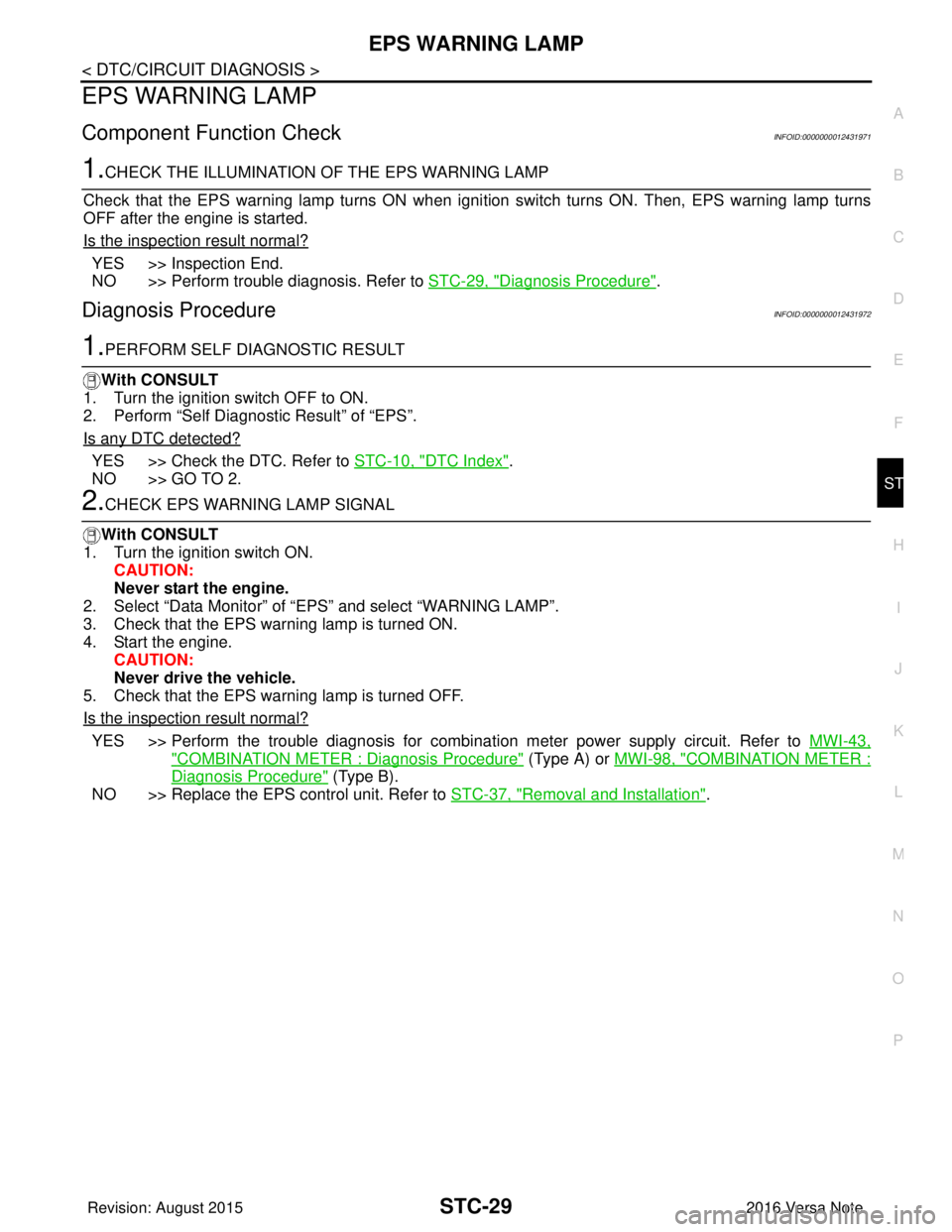
Check that the EPS warning lamp turns ON when igni tion switch turns ON. Then, EPS warning lamp turns
OFF after the engine is started.
Is the inspection result normal?
YES >> Inspection End.
NO >> Perform trouble diagnosis. Refer to STC-29, "
Diagnosis Procedure".
Diagnosis ProcedureINFOID:0000000012431972
1.PERFORM SELF DIAGNOSTIC RESULT
With CONSULT
1. Turn the ignition switch OFF to ON.
2. Perform “Self Diagnostic Result” of “EPS”.
Is any DTC detected?
YES >> Check the DTC. Refer to STC-10, "DTC Index".
NO >> GO TO 2.
2.CHECK EPS WARNING LAMP SIGNAL
With CONSULT
1. Turn the ignition switch ON.
CAUTION:
Never start the engine.
2. Select “Data Monitor” of “ EPS” and select “WARNING LAMP”.
3. Check that the EPS warning lamp is turned ON.
4. Start the engine. CAUTION:
Never drive the vehicle.
5. Check that the EPS warning lamp is turned OFF.
Is the inspection result normal?
YES >> Perform the trouble diagnosis for combination meter power supply circuit. Refer to MWI-43,
"COMBINATION METER : Diagnosis Procedure" (Type A) or MWI-98, "COMBINATION METER :
Diagnosis Procedure" (Type B).
NO >> Replace the EPS control unit. Refer to STC-37, "
Removal and Installation".
Revision: August 2015 2016 Versa Note
cardiagn.com
Page 3215 of 3641
EPS WARNING LAMP DOES NOT TURN OFFSTC-31
< SYMPTOM DIAGNOSIS >
C
DE
F
H I
J
K L
M A
B
STC
N
O P
EPS WARNING LAMP DOES NOT TURN OFF
DescriptionINFOID:0000000012431975
EPS warning lamp does not turn OFF several seconds after engine started.
Diagnosis ProcedureINFOID:0000000012431976
1.PERFORM SELF-DIAGNOSIS
With CONSULT
1. Turn the ignition switch OFF to ON.
2. Perform “Self Diagnostic Result” of “EPS”.
Is any DTC detected?
YES >> Check the DTC. Refer to STC-10, "DTC Index".
NO >> GO TO 2.
2.CHECK EPS WARNING LAMP
Perform the trouble diagnosis of EPS warning lamp. Refer to STC-29, "
Diagnosis Procedure".
Is the inspection result normal?
YES >> GO TO 3.
NO >> Repair or replace the specific malfunctioning part.
3.CHECK EPS CONTROL UNIT POWE R SUPPLY AND GROUND CIRCUIT
Perform the trouble diagnosis of EPS cont rol unit power supply and ground. Refer to STC-18, "
Diagnosis Pro-
cedure".
Is the inspection result normal?
YES >> Check that there is no malfunction in eac h harness connector pin terminal or disconnection.
NO >> Repair or replace the specific malfunctioning part.
Revision: August 2015 2016 Versa Note
cardiagn.com
Page 3216 of 3641
STC-32
< SYMPTOM DIAGNOSIS >
STEERING WHEEL TURNING FORCE IS HEAVY OR LIGHT
STEERING WHEEL TURNING FORCE IS HEAVY OR LIGHT
DescriptionINFOID:0000000012431977
Steering wheel turning force is heavy or light.
Diagnosis ProcedureINFOID:0000000012431978
1.PERFORM SELF DIAGNOSTIC RESULT
With CONSULT
1. Turn the ignition switch OFF to ON.
2. Perform “Self Diagnostic Result” of “EPS”.
Is any DTC detected?
YES >> Check the DTC. Refer to STC-10, "DTC Index".
NO >> GO TO 2.
2.CHECK THE ILLUMINATION OF THE EPS WARNING LAMP
Check that the EPS warning lamp turns ON when igni tion switch turns ON. Then, EPS warning lamp turns
OFF after the engine is started.
Is the inspection result normal?
YES >> GO TO 3.
NO >> Perform trouble diagnosis of EPS warning lamp. Refer to STC-29, "
Diagnosis Procedure".
3.CHECK EPS CONTROL UNIT SIGNAL (1)
With CONSULT
1. Start the engine. CAUTION:
Never drive the vehicle.
2. Select “ASSIST LEVEL” in “Data Monitor” of “EPS”.
Does the item in
“Data Monitor” indicate 100%?
YES >> GO TO 6.
NO >> GO TO 4.
4.CHECK EPS CONTROL UNIT SIGNAL (2)
With CONSULT
Select “BATTERY VOLT” in “Data Monitor” of “EPS”.
Does the item in
“Data Monitor” indicate 10 V or more?
YES >> GO TO 5.
NO >> Perform trouble diagnosis of EPS control unit power supply and ground. Refer to STC-18, "
Diag-
nosis Procedure".
5.CHECK EPS CONTROL UNIT SIGNAL (3)
With CONSULT
1. Select “ASSIST LEVEL” in “Data Monitor” of “EPS”.
2. Stop the EPS system until the item in “Data Monitor” becomes “100%”.
NOTE:
While stopping the EPS system, do not turn steering wheel.
3. Check that the symptom continues.
Does the symptom continue?
YES >> GO TO 6.
NO >> The assist torque decreases because of protection function. This is not malfunction. Inspection End.
6.CHECK EPS CONTROL UNIT SIGNAL (4)
With CONSULT
1. Start the engine. CAUTION:
Revision: August 2015 2016 Versa Note
cardiagn.com