2016 NISSAN NOTE check engine
[x] Cancel search: check enginePage 3176 of 3641

STR-24
< BASIC INSPECTION >
DIAGNOSIS AND REPAIR WORKFLOW
Is “S” connector circuit normal?
YES >> GO TO 9.
NO >> Repair as needed.
9.ENGINE ROTATION STATUS
Check that the engine can be rotated by hand.
Does the engine turn freely by hand?
YES >> Replace starter motor. Refer to STR-31, "Removal and Installation".
NO >> Perform further diagnosis of engine mechanical or powertrain mechanism. Once resolved, per-
form battery test again using Multitasking battery and electrical diagnostic station GR8-1200 NI.
Refer to the diagnostic station Instruction Manual for proper testing procedures.
Revision: August 2015 2016 Versa Note
cardiagn.com
Page 3177 of 3641
DIAGNOSIS AND REPAIR WORKFLOWSTR-25
< BASIC INSPECTION >
C
DE
F
G H
I
J
K L
M A
STR
NP
O
Work Flow (Without GR8-1200 NI)INFOID:0000000012432071
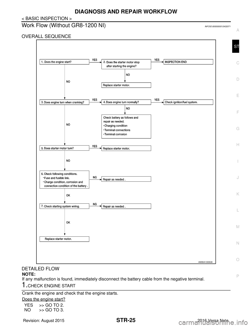
OVERALL SEQUENCE
DETAILED FLOW
NOTE:
If any malfunction is found, immediately disconnec
t the battery cable from the negative terminal.
1.CHECK ENGINE START
Crank the engine and check that the engine starts.
Does the engine start?
YES >> GO TO 2.
NO >> GO TO 3.
AWBIA1303GB
Revision: August 2015 2016 Versa Note
cardiagn.com
Page 3178 of 3641
STR-26
< BASIC INSPECTION >
DIAGNOSIS AND REPAIR WORKFLOW
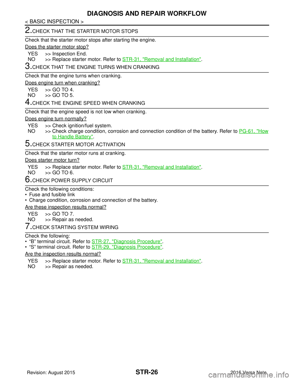
2.CHECK THAT THE STARTER MOTOR STOPS
Check that the starter motor stops after starting the engine.
Does the starter motor stop?
YES >> Inspection End.
NO >> Replace starter motor. Refer to STR-31, "
Removal and Installation".
3.CHECK THAT THE ENGINE TURNS WHEN CRANKING
Check that the engine turns when cranking.
Does engine turn when cranking?
YES >> GO TO 4.
NO >> GO TO 5.
4.CHECK THE ENGINE SPEED WHEN CRANKING
Check that the engine speed is not low when cranking.
Does engine turn normally?
YES >> Check ignition/fuel system.
NO >> Check charge condition, corrosion and connection condition of the battery. Refer to PG-61, "
How
to Handle Battery".
5.CHECK STARTER MOTOR ACTIVATION
Check that the starter motor runs at cranking.
Does starter motor turn?
YES >> Replace starter motor. Refer to STR-31, "Removal and Installation".
NO >> GO TO 6.
6.CHECK POWER SUPPLY CIRCUIT
Check the following conditions:
• Fuse and fusible link
• Charge condition, corrosion and connection of the battery.
Are these inspection results normal?
YES >> GO TO 7.
NO >> Repair as needed.
7.CHECK STARTING SYSTEM WIRING
Check the following:
• “B” terminal circuit. Refer to STR-27, "
Diagnosis Procedure".
• “S” terminal circuit. Refer to STR-29, "
Diagnosis Procedure".
Are the inspection results normal?
YES >> Replace starter motor. Refer to STR-31, "Removal and Installation".
NO >> Repair as needed.
Revision: August 2015 2016 Versa Note
cardiagn.com
Page 3179 of 3641
B TERMINAL CIRCUITSTR-27
< DTC/CIRCUIT DIAGNOSIS >
C
DE
F
G H
I
J
K L
M A
STR
NP
O
DTC/CIRCUIT DIAGNOSIS
B TERMINAL CIRCUIT
DescriptionINFOID:0000000012432072
Terminal “B” is constantly supplied with battery power.
Diagnosis ProcedureINFOID:0000000012432073
Regarding Wiring Diagram information, refer to
STR-10, "Wiring Diagram - With Intelligent Key System" or
STR-16, "
Wiring Diagram - Without Intelligent Key System".
CAUTION:
Perform diagnosis under the cond ition that the engine cannot start by the following procedure.
1. Remove fuel pump fuse.
2. Crank or start the engine (where possi ble) until the fuel pressure is released.
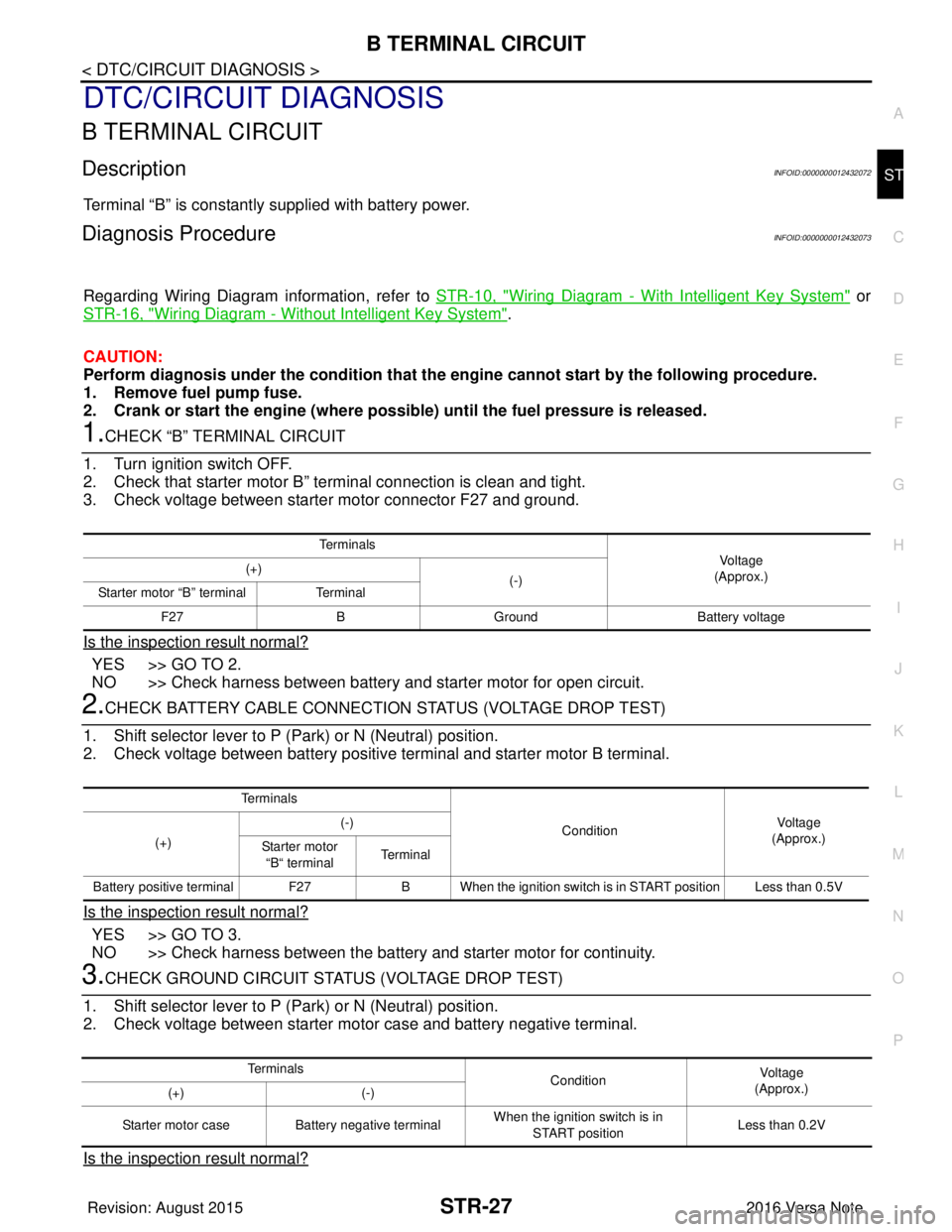
1.CHECK “B” TERMINAL CIRCUIT
1. Turn ignition switch OFF.
2. Check that starter motor B” terminal connection is clean and tight.
3. Check voltage between starter motor connector F27 and ground.
Is the inspection result normal?
YES >> GO TO 2.
NO >> Check harness between battery and starter motor for open circuit.
2.CHECK BATTERY CABLE CONNECTION STATUS (VOLTAGE DROP TEST)
1. Shift selector lever to P (P ark) or N (Neutral) position.
2. Check voltage between battery positive terminal and starter motor B terminal.
Is the inspection result normal?
YES >> GO TO 3.
NO >> Check harness between the battery and starter motor for continuity.
3.CHECK GROUND CIRCUIT STATUS (VOLTAGE DROP TEST)
1. Shift selector lever to P (P ark) or N (Neutral) position.
2. Check voltage between starter motor case and battery negative terminal.
Is the inspection result normal?
Te r m i n a l s
Voltage
(Approx.)
(+)
(-)
Starter motor “B” terminal Terminal
F27 BGround Battery voltage
Te r m i n a l s
ConditionVoltage
(Approx.)
(+) (-)
Starter motor “B“ terminal Terminal
Battery positive terminal F27 B When the ignition switch is in START position Less than 0.5V
Te r m i n a l s
ConditionVoltage
(Approx.)
(+) (-)
Starter motor case Battery negative terminal When the ignition switch is in
START position Less than 0.2V
Revision: August 2015
2016 Versa Note
cardiagn.com
Page 3180 of 3641

STR-28
< DTC/CIRCUIT DIAGNOSIS >
B TERMINAL CIRCUIT
YES >> “B” terminal circuit is OK. Further inspection is necessary. Refer to STR-21, "Work Flow (With
GR8-1200 NI)" or STR-25, "Work Flow (Without GR8-1200 NI)".
NO >> Check the starter motor case to engine mounting for high resistance.
Revision: August 2015 2016 Versa Note
cardiagn.com
Page 3181 of 3641
S CONNECTOR CIRCUITSTR-29
< DTC/CIRCUIT DIAGNOSIS >
C
DE
F
G H
I
J
K L
M A
STR
NP
O
S CONNECTOR CIRCUIT
DescriptionINFOID:0000000012432074
The starter motor magnetic switch is supplied with power when the ignition switch is turned to the START posi-
tion while the selector lever is in the P (Park) or N (Neutral) position.
Diagnosis ProcedureINFOID:0000000012432075
Regarding Wiring Diagram information, refer to
STR-10, "Wiring Diagram - With Intelligent Key System" or
STR-16, "
Wiring Diagram - Without Intelligent Key System".
CAUTION:
Perform diagnosis under the cond ition that engine cannot start by the following procedure.
1. Remove fuel pump fuse.
2. Crank or start the engine (where possi ble) until the fuel pressure is released.
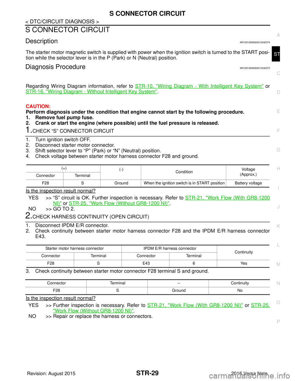
1.CHECK “S” CONNECTOR CIRCUIT
1. Turn ignition switch OFF.
2. Disconnect starter motor connector.
3. Shift selector lever to “P” (Park) or “N” (Neutral) position.
4. Check voltage between starter motor harness connector F28 and ground.
Is the inspection result normal?
YES >> “S” circuit is OK. Further inspection is necessary. Refer to STR-21, "Work Flow (With GR8-1200
NI)" or STR-25, "Work Flow (Without GR8-1200 NI)".
NO >> GO TO 2.
2.CHECK HARNESS CONTINUI TY (OPEN CIRCUIT)
1. Disconnect IPDM E/R connector.
2. Check continuity between starter motor harnes s connector F28 and the IPDM E/R harness connector
E43.
3. Check continuity between starter motor connector F28 terminal S and ground.
Is the inspection result normal?
YES >> Further inspection is necessary. Refer to STR-21, "Work Flow (With GR8-1200 NI)" or STR-25,
"Work Flow (Without GR8-1200 NI)".
NO >> Repair or replace the harness or connectors.
(+) (-)
Condition Voltage
(Approx.)
Connector Terminal
F28 SGround When the ignition switch is in START position Battery voltage
Starter motor harness connector IPDM E/R harness connector
Continuity
Connector TerminalConnector Terminal
F28 SE43 6Yes
Connector Terminal –Continuity
F28 SGround No
Revision: August 2015 2016 Versa Note
cardiagn.com
Page 3185 of 3641

STC-1
STEERING
C
DE
F
H I
J
K L
M
SECTION STC
A
B
STC
N
O P
CONTENTS
STEERING CONTROL SYSTEM
PRECAUTION ....... ........................................3
PRECAUTIONS .............................................. .....3
Precaution for Supplemental Restraint System
(SRS) "AIR BAG" and "SEAT BELT PRE-TEN-
SIONER" ............................................................. ......
3
Service Notice and Precautions for EPS System ......3
SYSTEM DESCRIPTION ..............................4
COMPONENT PARTS ................................... .....4
Component Parts Location .................................. ......4
EPS Control Unit .......................................................5
EPS Motor, Torque Sensor, Reduction Gear ............5
DIAGNOSIS SYSTEM (EPS CONTROL UNIT)
.....
6
CONSULT Function ............................................ ......6
ECU DIAGNOSIS INFORMATION ...............8
EPS CONTROL UNIT ..................................... .....8
Reference Value ................................................. ......8
Fail-Safe ....................................................................9
Protection Function .................................................10
DTC Inspection Priority Chart ............................. ....10
DTC Index ........................................................... ....10
WIRING DIAGRAM ......................................11
EPS SYSTEM ... .............................................. ....11
Wiring Diagram ................................................... ....11
BASIC INSPECTION ...................................15
DIAGNOSIS AND REPAIR WORKFLOW ..... ....15
Work Flow ........................................................... ....15
Diagnostic Work Sheet ............................................16
DTC/CIRCUIT DIAGNOSIS .........................18
C1601 BATTERY POWER SUPPLY .................18
DTC Logic ........................................................... ....18
Diagnosis Procedure ........................................... ....18
C1604 TORQUE SENSOR ................................21
DTC Logic ................................................................21
Diagnosis Procedure ...............................................21
C1606 EPS MOTOR ..........................................23
DTC Logic ................................................................23
Diagnosis Procedure ...............................................23
Component Inspection .............................................23
C1607, C1608 EPS CONTROL UNIT ...............25
DTC Logic ................................................................25
Diagnosis Procedure ...............................................25
C1609 VEHICLE SPEED SIGNAL ....................26
Description ...............................................................26
DTC Logic ................................................................26
Diagnosis Procedure ...............................................26
C1610 ENGINE STATUS SIGNAL ...................27
Description ...............................................................27
DTC Logic ................................................................27
Diagnosis Procedure ...............................................27
U1000 CAN COMM CIRCUIT ...........................28
Description ...............................................................28
DTC Logic ................................................................28
Diagnosis Procedure ...............................................28
EPS WARNING LAMP ......................................29
Component Function Check ....................................29
Diagnosis Procedure ...............................................29
SYMPTOM DIAGNOSIS ..............................30
EPS WARNING LAMP DOES NOT TURN ON ...30
Description ........................................................... ....30
Diagnosis Procedure ...............................................30
EPS WARNING LAMP DOES NOT TURN
OFF ....................................................................
31
Description ...............................................................31
Revision: August 2015 2016 Versa Note
cardiagn.com
Page 3187 of 3641
PRECAUTIONSSTC-3
< PRECAUTION >
C
DE
F
H I
J
K L
M A
B
STC
N
O P
PRECAUTION
PRECAUTIONS
Precaution for Supplemental Restraint System (SRS) "AIR BAG" and "SEAT BELT
PRE-TENSIONER"
INFOID:0000000012431939
The Supplemental Restraint System such as “AIR BAG” and “SEAT BELT PRE-TENSIONER”, used along
with a front seat belt, helps to reduce the risk or severi ty of injury to the driver and front passenger for certain
types of collision. Information necessary to service the system safely is included in the SR and SB section of
this Service Manual.
WARNING:
• To avoid rendering the SRS inoper ative, which could increase the risk of personal injury or death in
the event of a collision which would result in air bag inflation, all maintenance must be performed by
an authorized NISSAN/INFINITI dealer.
• Improper maintenance, including in correct removal and installation of the SRS, can lead to personal
injury caused by unintentional act ivation of the system. For removal of Spiral Cable and Air Bag
Module, see the SR section.
• Do not use electrical test equipm ent on any circuit related to the SRS unless instructed to in this
Service Manual. SRS wiring harnesses can be identi fied by yellow and/or orange harnesses or har-
ness connectors.
PRECAUTIONS WHEN USING POWER TOOLS (AIR OR ELECTRIC) AND HAMMERS
WARNING:
• When working near the Airbag Diagnosis Sensor Un it or other Airbag System sensors with the Igni-
tion ON or engine running, DO NOT use air or el ectric power tools or strike near the sensor(s) with a
hammer. Heavy vibration could activate the sensor( s) and deploy the air bag(s), possibly causing
serious injury.
• When using air or electric power tools or hammers, always switch the Ignition OFF, disconnect the
battery and wait at least three mi nutes before performing any service.
Service Notice and Precautions for EPS SystemINFOID:0000000012431940
• Check the following item when performing the trouble diagnosis:
- Check for possible causes of the malfunction by inte rviewing the customer as to what conditions were
present when the symptom occurred.
- Check if the steering wheel and the EPS control unit are genuine parts.
- Check if the air pressure and size of each tire is correct.
- Check if the installation of the links and suspension components are correct.
- Check if the tires are worn evenly, indicating the wheel alignment is correct.
- Check if the installation of the steering column and t he steering gear are correct. Check for loose bolts, dam-
aged links, cracked boots and leaking grease, etc.
- Check for damage or modification to suspension or body resulting in increased weight or altered ground clearance.
- Check if the battery voltage is proper.
- Check the EPS control unit harness to be sure the harness connectors are fully seated.
• Before connecting or disconnecting the EPS control uni t harness connector, turn ignition switch “OFF” and
disconnect the battery cable from the negative terminal. Battery voltage is applied to the EPS control unit
even if ignition switch is turned “OFF”.
Revision: August 2015 2016 Versa Note
cardiagn.com