2016 NISSAN NOTE ECU
[x] Cancel search: ECUPage 3508 of 3641

VTL-2
< PRECAUTION >
PRECAUTIONS
PRECAUTION
PRECAUTIONS
Precaution for Supplemental Restraint System (SRS) "AIR BAG" and "SEAT BELT
PRE-TENSIONER"
INFOID:0000000012430544
The Supplemental Restraint System such as “A IR BAG” and “SEAT BELT PRE-TENSIONER”, used along
with a front seat belt, helps to reduce the risk or severity of injury to the driver and front passenger for certain
types of collision. Information necessary to service the system safely is included in the SR and SB section of
this Service Manual.
WARNING:
• To avoid rendering the SRS inopera tive, which could increase the risk of personal injury or death in
the event of a collision which would result in air bag inflation, all maintenance must be performed by
an authorized NISSAN/INFINITI dealer.
• Improper maintenance, including in correct removal and installation of the SRS, can lead to personal
injury caused by unintent ional activation of the system. For re moval of Spiral Cable and Air Bag
Module, see the SR section.
• Do not use electrical test equipmen t on any circuit related to the SRS unless instructed to in this
Service Manual. SRS wiring harn esses can be identified by yellow and/or orange harnesses or har-
ness connectors.
PRECAUTIONS WHEN USING POWER TOOLS (AIR OR ELECTRIC) AND HAMMERS
WARNING:
• When working near the Airbag Diagnosis Sensor Unit or other Airbag System sensors with the Igni-
tion ON or engine running, DO NOT use air or electri c power tools or strike near the sensor(s) with a
hammer. Heavy vibration could activate the sensor( s) and deploy the air bag(s), possibly causing
serious injury.
• When using air or electric power tools or hammers , always switch the Ignition OFF, disconnect the
battery and wait at least three minutes before performing any service.
Precaution for WorkINFOID:0000000012430545
• When removing or disassembling each component, be careful not to damage or deform it. If a component may be subject to interference, be sure to protect it with a shop cloth.
• When removing (disengaging) components with a screwdriver or similar tool, be sure to wrap the component with a shop cloth or vinyl tape to protect it.
• Protect the removed parts with a shop cloth and prevent them from being dropped.
• Replace a deformed or damaged clip.
• If a part is specified as a non-reusable part, always replace it with a new one.
• Be sure to tighten bolts and nuts securely to the specified torque.
• After installation is complete, be sure to check that each part works properly.
• Follow the steps below to clean components:
- Water soluble dirt:
• Dip a soft cloth into lukewarm water, wring the water out of the cloth and wipe the dirty area.
• Then rub with a soft, dry cloth.
- Oily dirt:
• Dip a soft cloth into lukewarm water with mild detergent (concentration: within 2 to 3%) and wipe the dirty area.
• Then dip a cloth into fresh water, wring the water out of the cloth and wipe the detergent off.
• Then rub with a soft, dry cloth.
- Do not use organic solvent such as thinner, benzene, alcohol or gasoline.
- For genuine leather seats, use a genuine leather seat cleaner.
Revision: August 2015 2016 Versa Note
cardiagn.com
Page 3513 of 3641

DUCT AND GRILLEVTL-7
< REMOVAL AND INSTALLATION >
C
DE
F
G H
J
K L
M A
B
VTL
N
O P
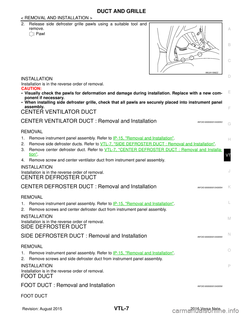
2. Release side defroster grille pawls using a suitable tool and remove.
: Pawl
INSTALLATION
Installation is in the reverse order of removal.
CAUTION:
• Visually check the pawls for deformation and dama ge during installation. Replace with a new com-
ponent if necessary.
• When installing side defroster grille, check that all pawls are securely placed into instrument panel assembly.
CENTER VENTILATOR DUCT
CENTER VENTILATOR DUCT : Removal and InstallationINFOID:0000000012430553
REMOVAL
1. Remove instrument panel assembly. Refer to IP-15, "Removal and Installation".
2. Remove side defroster ducts. Refer to VTL-7, "
SIDE DEFROSTER DUCT : Removal and Installation".
3. Remove center defroster duct. Refer to VTL-7, "
CENTER DEFROSTER DUCT : Removal and Installa-
tion".
4. Remove screw and center ventilator duct from instrument panel assembly.
INSTALLATION
Installation is in the reverse order of removal.
CENTER DEFROSTER DUCT
CENTER DEFROSTER DUCT : Removal and InstallationINFOID:0000000012430554
REMOVAL
1. Remove instrument panel assembly. Refer to IP-15, "Removal and Installation".
2. Remove screws and center defroster duct from instrument panel assembly.
INSTALLATION
Installation is in the reverse order of removal.
SIDE DEFROSTER DUCT
SIDE DEFROSTER DUCT : Removal and InstallationINFOID:0000000012430555
REMOVAL
1. Remove instrument panel assembly. Refer to IP-15, "Removal and Installation".
2. Remove screws and side defroster duct from instrument panel assembly.
INSTALLATION
Installation is in the reverse order of removal.
FOOT DUCT
FOOT DUCT : Removal and InstallationINFOID:0000000012430556
FOOT DUCT
AWJIA1098ZZ
Revision: August 2015 2016 Versa Note
cardiagn.com
Page 3516 of 3641

WCS
WCS-1
DRIVER INFORMATION & MULTIMEDIA
C
DE
F
G H
I
J
K L
M B
SECTION WCS
A
O P
CONTENTS
WARNING CHIME SYSTEM
HOW TO USE THIS MANU AL ......................3
APPLICATION NOTICE ................................. .....3
Information .......................................................... ......3
PRECAUTION ...............................................4
PRECAUTIONS .............................................. .....4
Precaution for Supplemental Restraint System
(SRS) "AIR BAG" and "SEAT BELT PRE-TEN-
SIONER" ............................................................. ......
4
SYSTEM DESCRIPTION ..............................5
COMPONENT PARTS ................................... .....5
Component Parts Location .................................. ......5
Combination Meter ....................................................5
SYSTEM ..............................................................7
WARNING CHIME SYSTEM .......................................7
WARNING CHIME SYSTEM : System Description
......
7
WARNING CHIME SYSTEM : Fail-safe ....................8
LIGHT REMINDER WARNING CHIME ................. ......8
LIGHT REMINDER WARNING CHIME : Light Re-
minder Warning .........................................................
8
PARKING BRAKE RELEASE WARNING CHIME ......9
PARKING BRAKE RELEASE WARNING CHIME
: Parking Brake Release Warning Chime ............ ......
9
SEAT BELT REMINDER WARNING CHIME ........ ....10
SEAT BELT REMINDER WARNING CHIME :
Seat belt Warning ....................................................
10
KEY WARNING CHIME (WITHOUT INTELLIGENT
KEY) ....................................................................... ....
11
KEY WARNING CHIME (WITHOUT INTELLI-
GENT KEY) : Key Warning Chime ..........................
11
DIAGNOSIS SYSTEM (COMBINATION
METER) .............................................................
13
TYPE A ............................................ ...........................13
TYPE A : On Board Diagnosis Function .............. ....13
TYPE A : CONSULT Function (METER/M&A) ........14
TYPE B ............................................ ...........................16
TYPE B : On Board Diagnosis Function .............. ....16
TYPE B : CONSULT Function (METER/M&A) ........18
DIAGNOSIS SYSTEM (BCM) (WITH INTELLI-
GENT KEY SYSTEM) .......................................
21
COMMON ITEM ..................................................... ....21
COMMON ITEM : CONSULT Function (BCM -
COMMON ITEM) .....................................................
21
BUZZER ................................................................. ....22
BUZZER : CONSULT Function (BCM - BUZZER) ....22
DIAGNOSIS SYSTEM (BCM) (WITHOUT IN-
TELLIGENT KEY SYSTEM) .............................
23
COMMON ITEM ..................................................... ....23
COMMON ITEM : CONSULT Function (BCM -
COMMON ITEM) .....................................................
23
BUZZER ................................................................. ....24
BUZZER : CONSULT Function (BCM - BUZZER) ....24
ECU DIAGNOSIS INFORMATION ..............25
BCM, COMBINATION METER .........................25
List of ECU Reference ......................................... ....25
WIRING DIAGRAM ......................................26
WARNING CHIME SYSTEM .............................26
Wiring Diagram .................................................... ....26
BASIC INSPECTION ...................................32
DIAGNOSIS AND REPAIR WORK FLOW .......32
Revision: August 2015 2016 Versa Note
cardiagn.com
Page 3529 of 3641

WCS-14
< SYSTEM DESCRIPTION >
DIAGNOSIS SYSTEM (COMBINATION METER)
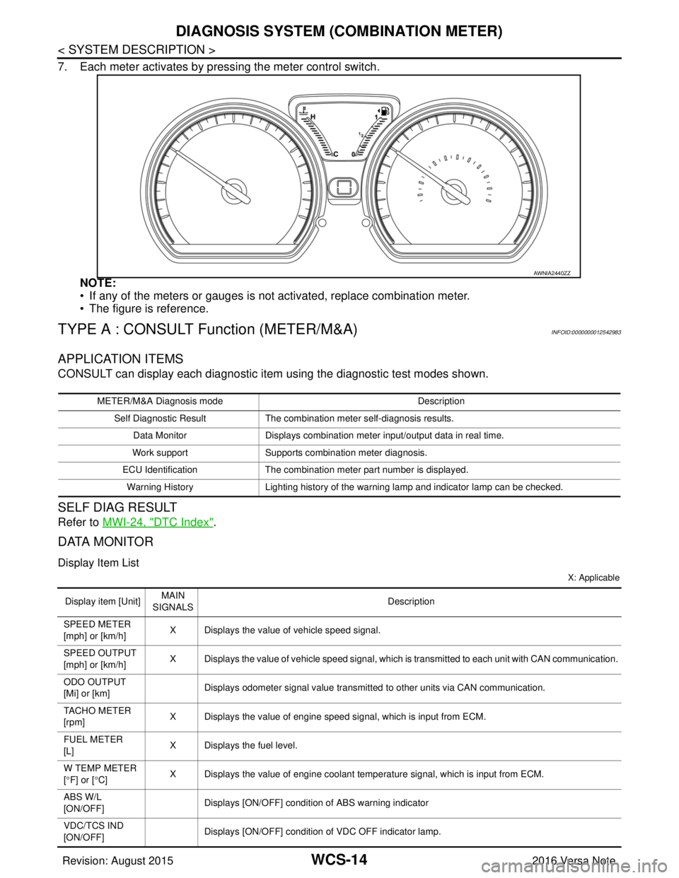
7. Each meter activates by pressing the meter control switch.NOTE:
• If any of the meters or gauges is not activated, replace combination meter.
• The figure is reference.
TYPE A : CONSULT Function (METER/M&A)INFOID:0000000012542983
APPLICATION ITEMS
CONSULT can display each diagnostic item using the diagnostic test modes shown.
SELF DIAG RESULT
Refer to MWI-24, "DTC Index".
DATA MONITOR
Display Item List
X: Applicable
AWNIA2440ZZ
METER/M&A Diagnosis mode Description
Self Diagnostic Result The combination meter self-diagnosis results.
Data Monitor Displays combination meter input/output data in real time.
Work support Supports combination meter diagnosis.
ECU Identification The combination meter part number is displayed.
Warning History Lighting history of the warning lamp and indicator lamp can be checked.
Display item [Unit]MAIN
SIGNALS Description
SPEED METER
[mph] or [km/h] X Displays the value of vehicle speed signal.
SPEED OUTPUT
[mph] or [km/h] X Displays the value of vehicle speed signal, which is transmitted to each unit with CAN communication.
ODO OUTPUT
[Mi] or [km] Displays odometer signal value transmitted to other units via CAN communication.
TACHO METER
[rpm] X Displays the value of engine speed signal, which is input from ECM.
FUEL METER
[L] X Displays the fuel level.
W TEMP METER
[ ° F] or [ °C] X Displays the value of engine coolant temperature signal, which is input from ECM.
ABS W/L
[ON/OFF] Displays [ON/OFF] conditio
n of ABS warning indicator
VDC/TCS IND
[ON/OFF] Displays [ON/OFF] condition
of VDC OFF indicator lamp.
Revision: August 2015 2016 Versa Note
cardiagn.com
Page 3533 of 3641

WCS-18
< SYSTEM DESCRIPTION >
DIAGNOSIS SYSTEM (COMBINATION METER)
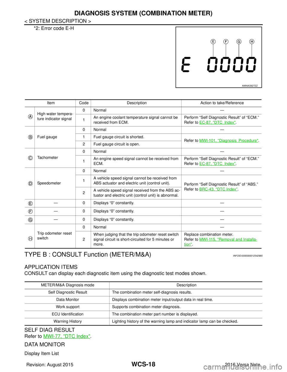
*2: Error code E-H
TYPE B : CONSULT Function (METER/M&A)INFOID:0000000012542985
APPLICATION ITEMS
CONSULT can display each diagnostic item using the diagnostic test modes shown.
SELF DIAG RESULT
Refer to MWI-77, "DTC Index".
DATA MONITOR
Display Item List
AWNIA3627ZZ
Item Code Description Action to take/Reference
High water tempera-
ture indicator signal 0Normal
—
1 An engine coolant temperature signal cannot be
received from ECM. Perform “Self Diagnostic Result” of “ECM.”
Refer to
EC-87, "
DTCIndex".
Fuel gauge 0Normal
—
1 Fuel gauge circuit is shorted. Refer to MWI-101, "
DiagnosisProcedure".
2 Fuel gauge circuit is open.
Tachometer 0Normal
—
1 An engine speed signal cannot be received from
ECM. Perform “Self Diagnostic Result” of “ECM.”
Refer to
EC-87, "
DTCIndex".
Speedometer 0Normal
—
1 A vehicle speed signal cannot be received from
ABS actuator and electric unit (control unit).
Perform “Self Diagnostic Result” of “ABS.”
Refer to BRC-43, "
DTC Index".
2 A vehicle speed signal re
ceived from the ABS ac-
tuator and electric unit (control unit) is abnormal.
— 0 Displays “0” constantly. —
— 0 Displays “0” constantly. —
— 0 Displays “0” constantly. —
Trip odometer reset
switch 0Normal
—
2 When judging that the trip odometer reset switch
signal circuit is short-circuited for 5 minutes or
more. Replace combination meter.
Refer to
MWI-115, "
Removal and Installa-
tion".
METER/M&A Diagnosis mode Description
Self Diagnostic Result The combination meter self-diagnosis results.
Data Monitor Displays combination meter input/output data in real time.
Work support Supports combination meter diagnosis.
ECU Identification The combination meter part number is displayed.
Warning History Lighting history of the warning lamp and indicator lamp can be checked.
Revision: August 2015 2016 Versa Note
cardiagn.com
Page 3536 of 3641

WCS
DIAGNOSIS SYSTEM (BCM) (WITH INTELLIGENT KEY SYSTEM)
WCS-21
< SYSTEM DESCRIPTION >
C
D E
F
G H
I
J
K L
M B A
O P
DIAGNOSIS SYSTEM (BCM) (WIT H INTELLIGENT KEY SYSTEM)
COMMON ITEM
COMMON ITEM : CONSULT Function (BCM - COMMON ITEM)INFOID:0000000012542986
APPLICATION ITEM
CONSULT performs the following functions via CAN communication with BCM.
SYSTEM APPLICATION
BCM can perform the following functions.
Direct Diagnostic Mode Description
ECU Identification The BCM part number is displayed.
Self Diagnostic Result The BCM self diagnostic results are displayed.
Data Monitor The BCM input/output data is displayed in real time.
Active Test The BCM activates outputs to test components.
Work support The settings for BCM functions can be changed.
Configuration • The vehicle specification can be read and saved.
• The vehicle specification can be written when replacing BCM.
CAN DIAG SUPPORT MNTR The result of transmit/receive diagnosis of CAN communication is displayed.
System Sub System Direct Diagnostic Mode
ECU Identification
Self Diagnostic Result
Data Monitor
Active Test
Work support
Configuration
CAN DIAG SUPPORT MNTR
Door lock
DOOR LOCK ×××
Rear window defogger REAR DEFOGGER ××
Warning chime BUZZER ××
Interior room lamp timer INT LAMP ×××
Exterior lamp HEAD LAMP ×××
Wiper and washer WIPER ×××
Turn signal and hazard warning lamps FLASHER ×××
Air conditioner AIR CONDITIONER ×
Intelligent Key system INTELLIGENT KEY ××××
Combination switch COMB SW ×
BCM BCM× × ×××
Immobilizer IMMU ××××
Interior room lamp battery saver BATTERY SAVER ×××
Vehicle security system THEFT ALM ××
RAP system RETAINED PWR ×
Signal buffer system SIGNAL BUFFER ×
TPMS AIR PRESSURE MONITOR ××××
Panic alarm system PANIC ALARM ×
Revision: August 2015 2016 Versa Note
cardiagn.com
Page 3538 of 3641

WCS
DIAGNOSIS SYSTEM (BCM) (WITHOUT INTELLIGENT KEY SYSTEM)WCS-23
< SYSTEM DESCRIPTION >
C
DE
F
G H
I
J
K L
M B A
O P
DIAGNOSIS SYSTEM (BCM) (WITHO UT INTELLIGENT KEY SYSTEM)
COMMON ITEM
COMMON ITEM : CONSULT Function (BCM - COMMON ITEM)INFOID:0000000012542988
APPLICATION ITEM
CONSULT performs the following functions via CAN communication with BCM.
SYSTEM APPLICATION
BCM can perform the following functions.
Direct Diagnostic Mode Description
ECU Identification The BCM part number is displayed.
Self Diagnostic Result The BCM self diagnostic results are displayed.
Data Monitor The BCM input/output data is displayed in real time.
Active Test The BCM activates outputs to test components.
Work support The settings for BCM functions can be changed.
Configuration • The vehicle specification can be read and saved.
• The vehicle specification can be written when replacing BCM.
CAN DIAG SUPPORT MNTR The result of transmit/receive diagnosis of CAN communication is displayed.
System Sub System Direct Diagnostic Mode
ECU Identification
Self Diagnostic Result
Data Monitor
Active Test
Work support
Configuration
CAN DIAG SUPPORT MNTR
Door lock
DOOR LOCK ×××
Rear window defogger REAR DEFOGGER ××
Warning chime BUZZER ××
Interior room lamp timer INT LAMP ×××
Remote keyless entry system MULTI REMOTE ENT ×××
Exterior lamp HEAD LAMP ×××
Wiper and washer WIPER ×××
Turn signal and hazard warning lamps FLASHER ××
Air conditioner AIR CONDITIONER ×
Combination switch COMB SW ×
BCM BCM× × ×××
Immobilizer IMMU ×××
Interior room lamp battery saver BATTERY SAVER ×××
Vehicle security system THEFT ALM ××
RAP system RETAINED PWR ××
Signal buffer system SIGNAL BUFFER ×
TPMS AIR PRESSURE MONITOR ××××
Panic alarm system PANIC ALARM ×
Revision: August 2015 2016 Versa Note
cardiagn.com
Page 3540 of 3641

WCS
BCM, COMBINATION METERWCS-25
< ECU DIAGNOSIS INFORMATION >
C
DE
F
G H
I
J
K L
M B A
O P
ECU DIAGNOSIS INFORMATION
BCM, COMBINATION METER
List of ECU ReferenceINFOID:0000000012432683
ECU Reference
BCM
(with Intelligent Key system) BCS-30, "
Reference Value"
BCS-48, "Fail-safe"
BCS-49, "DTCInspectionPriorityChart"
BCS-50, "DTCIndex"
BCM
(without Intelligent Key system)BCS-101, "
Reference Value"
BCS-115, "Fail-safe"
BCS-115, "DTCInspectionPriorityChart"
BCS-115, "DTCIndex"
COMBINATION METER
(TYPE A)
MWI-21, "
Reference Value"
MWI-23, "Fail-safe"
MWI-24, "DTC Index"
COMBINATION METER
(TYPE B)MWI-74, "
Reference Value"
MWI-77, "Fail-safe"
MWI-77, "DTC Index"
Revision: August 2015
2016 Versa Note
cardiagn.com