2016 NISSAN NOTE current sensor
[x] Cancel search: current sensorPage 1505 of 3641
![NISSAN NOTE 2016 Service Repair Manual EC-378
< DTC/CIRCUIT DIAGNOSIS >[HR16DE]
P1554 BATTERY CURRENT SENSOR
Diagnosis Procedure
INFOID:0000000012431588
1.CHECK GROUND CONNECTION
1. Turn ignition switch OFF.
2. Check ground connection E15.](/manual-img/5/57363/w960_57363-1504.png "NISSAN NOTE 2016 Service Repair Manual EC-378
< DTC/CIRCUIT DIAGNOSIS >[HR16DE]
P1554 BATTERY CURRENT SENSOR
Diagnosis Procedure
INFOID:0000000012431588
1.CHECK GROUND CONNECTION
1. Turn ignition switch OFF.
2. Check ground connection E15.")
EC-378
< DTC/CIRCUIT DIAGNOSIS >[HR16DE]
P1554 BATTERY CURRENT SENSOR
Diagnosis Procedure
INFOID:0000000012431588
1.CHECK GROUND CONNECTION
1. Turn ignition switch OFF.
2. Check ground connection E15. Refer to Ground Inspection in GI-44, "
Circuit Inspection".
Is the inspection result normal?
YES >> GO TO 2.
NO >> Repair or replace ground connection.
2.CHECK BATTERY CURRENT SENSO R POWER SUPPLY CIRCUIT
1. Disconnect battery current sensor harness connector.
2. Turn ignition switch ON.
3. Check the voltage between battery current sensor harness connector and ground.
Is the inspection result normal?
YES >> GO TO 3.
NO >> Repair open circuit or sort to ground or short to power in harness or connectors.
3.CHECK BATTERY CURRENT SENSOR GROUND CIRCUIT FOR OPEN AND SHORT
1. Turn ignition switch OFF.
2. Disconnect ECM harness connector.
3. Check the continuity between battery current sensor harness connector and ECM harness connector.
4. Also check harness for short to ground and short to power.
Is the inspection result normal?
YES >> GO TO 4.
NO >> Repair open circuit or sort to ground or short to power in harness or connectors.
4.CHECK BATTERY CURRENT SENSOR INPUT SIGNAL CIRCUIT FOR OPEN AND SHORT
1. Check the continuity between battery current sensor harness connector and ECM harness connector.
2. Also check harness for short to ground and short to power.
Is the inspection result normal?
YES >> GO TO 5.
NO >> Repair open circuit or sort to ground or short to power in harness or connectors.
5.CHECK BATTERY CURRENT SENSOR
Refer to EC-379, "
Component Inspection".
Is the inspection result normal?
YES >> GO TO 6.
NO >> Replace battery negative cable assembly.
6.CHECK INTERMITTENT INCIDENT
Refer to GI-42, "
Intermittent Incident".
Battery current sensor
Ground Voltage
Connector Terminal
F9 1 Ground Approx. 5V
Battery current sensor ECM Continuity
Connector Terminal Connector Terminal
F9 3 F11 68 Existed
Battery current sensor ECM Continuity
Connector Terminal Connector Terminal
F9 4 F11 58 Existed
Revision: August 2015 2016 Versa Note
cardiagn.com
Page 1506 of 3641
![NISSAN NOTE 2016 Service Repair Manual P1554 BATTERY CURRENT SENSOREC-379
< DTC/CIRCUIT DIAGNOSIS > [HR16DE]
C
D
E
F
G H
I
J
K L
M A
EC
NP
O
>> INSPECTION END
Component InspectionINFOID:0000000012431589
1.CHECK BATTERY CURRENT SENSOR
1. Re](/manual-img/5/57363/w960_57363-1505.png "NISSAN NOTE 2016 Service Repair Manual P1554 BATTERY CURRENT SENSOREC-379
< DTC/CIRCUIT DIAGNOSIS > [HR16DE]
C
D
E
F
G H
I
J
K L
M A
EC
NP
O
>> INSPECTION END
Component InspectionINFOID:0000000012431589
1.CHECK BATTERY CURRENT SENSOR
1. Re")
P1554 BATTERY CURRENT SENSOREC-379
< DTC/CIRCUIT DIAGNOSIS > [HR16DE]
C
D
E
F
G H
I
J
K L
M A
EC
NP
O
>> INSPECTION END
Component InspectionINFOID:0000000012431589
1.CHECK BATTERY CURRENT SENSOR
1. Reconnect harness connectors disconnected.
2. Disconnect battery negative cable.
3. Install jumper cable between battery negative terminal and body ground.
4. Turn ignition switch ON.
5. Check the voltage between ECM harness connector and ground.
Is the inspection result normal?
YES >> INSPECTION END
NO >> Replace battery negative cable assembly.
ECM Ground Voltage
Connector Terminal
F11 58
(Battery current sensor signal) Ground Approx. 2.5V
JPBIA3287ZZ
Revision: August 2015
2016 Versa Note
cardiagn.com
Page 2421 of 3641
![NISSAN NOTE 2016 Service Repair Manual MWI
SYSTEMMWI-63
< SYSTEM DESCRIPTION > [TYPE B]
C
D
E
F
G H
I
J
K L
M B A
O P
SPEEDOMETER
SPEEDOMETER : System DescriptionINFOID:0000000012432603
SYSTEM DIAGRAM
DESCRIPTION
The ABS actuator and elect](/manual-img/5/57363/w960_57363-2420.png "NISSAN NOTE 2016 Service Repair Manual MWI
SYSTEMMWI-63
< SYSTEM DESCRIPTION > [TYPE B]
C
D
E
F
G H
I
J
K L
M B A
O P
SPEEDOMETER
SPEEDOMETER : System DescriptionINFOID:0000000012432603
SYSTEM DIAGRAM
DESCRIPTION
The ABS actuator and elect")
MWI
SYSTEMMWI-63
< SYSTEM DESCRIPTION > [TYPE B]
C
D
E
F
G H
I
J
K L
M B A
O P
SPEEDOMETER
SPEEDOMETER : System DescriptionINFOID:0000000012432603
SYSTEM DIAGRAM
DESCRIPTION
The ABS actuator and electric unit (control unit) receives each wheel speed sensor signal and provides a vehi-
cle speed signal to the combination meter via CAN communication.
TACHOMETER
Information display Trip com-
puterCurrent fuel consump-
tion
• When reception time of an abnormal signal is 2 seconds or
less, the last received datum is used for calculation to indi-
cate the result.
• When reception time of an abnormal signal is more than two seconds, the last result calculated during normal condition is
indicated.
Average fuel consump-
tion
Distance to empty
Odo/trip meter An indicated value is maintained at communications blackout.
Buzzer The buzzer turns OFF by suspending communication.
Warning lamp/indicator lamp ABS warning lamp
The lamp turns ON by suspending communication.
Slip indicator lamp
Malfunction indicator lamp (MIL)
VDC OFF indicator lamp
EPS warning lamp
Brake warning lamp
High beam indicator lamp
The lamp turns OFF by suspending communication.
Turn signal indicator lamp
Door warning lamp
Light indicator lamp
Engine oil pressure warning lamp
High water temperature warning
lamp
Key warning lamp
O/D OFF indicator lamp
Shift P warning lamp
Engine start operation indicator lamp
Function
Specifications
AWNIA2379GB
Revision: August 2015 2016 Versa Note
cardiagn.com
Page 2588 of 3641

PG
PG-1
ELECTRICAL & POWER CONTROL
C
DE
F
G H
I
J
K L
B
SECTION PG
A
O P
N
CONTENTS
POWER SUPPLY, GROUND & CIRCUIT ELEMENTS
PRECAUTION .......
........................................3
PRECAUTIONS .............................................. .....3
Precaution for Supplemental Restraint System
(SRS) "AIR BAG" and "SEAT BELT PRE-TEN-
SIONER" ............................................................. ......
3
Precaution for Power Generation Voltage Variable
Control System ..........................................................
3
PREPARATION ............................................4
PREPARATION .............................................. .....4
Special Service Tools .......................................... ......4
Commercial Service Tool ..........................................4
SYSTEM DESCRIPTION ..............................5
ELECTRICAL UNITS LOCATION .................. .....5
Electrical Units Location ...................................... ......5
COMPONENT PARTS ........................................9
Circuit Breaker (Built Into BCM) .......................... ......9
Harness Connector ...................................................9
Standardized Relay ............................................. ....12
WIRING DIAGRAM ......................................15
POWER SUPPLY ROUTING CIRCUIT .......... ....15
Wiring Diagram — Battery Power Supply — ....... ....15
Wiring Diagram — Accessory Power Supply — .....23
Wiring Diagram — Ignition Power Supply — ..........27
GROUND ............................................................35
Ground Distribution ............................................. ....35
HARNESS ...................................................... ....42
Harness Layout ................................................... ....42
FUSE BLOCK - JUNCTION BOX (J/B) .............58
Terminal Arrangement ............................................58
FUSE AND FUSIBLE LINK BOX ................... ....59
Terminal Arrangement ............................................59
IPDM E/R (INTELLIGENT POWER DISTRI-
BUTION MODULE ENGINE ROOM) ................
60
IPDM E/R Terminal Arrangement ........................ ....60
BASIC INSPECTION ...................................61
BATTERY ..........................................................61
How to Handle Battery ......................................... ....61
Work Flow ................................................................61
INSPECTION AND ADJUSTMENT ..................64
ADDITIONAL SERVICE WHEN REMOVING BAT-
TERY NEGATIVE TERMINAL ............................... ....
64
ADDITIONAL SERVICE WHEN REMOVING
BATTERY NEGATIVE TERMINAL : Special Re-
pair Requirement .....................................................
64
FUSE INSPECTION ..........................................65
How To Check .........................................................65
FUSIBLE LINK INSPECTION ...........................69
Fusible Link .............................................................69
REMOVAL AND INSTALLATION ...............70
BATTERY ..........................................................70
Exploded View ..................................................... ....70
Removal and Installation (Battery) ..........................70
Removal and Installation (Battery Tray) ..................71
BATTERY TERMINAL WITH FUSIBLE LINK ...72
Exploded View .........................................................72
Removal and Installation .........................................72
BATTERY CURRENT SENSOR .......................73
Exploded View .........................................................73
Removal and Installation .........................................73
SERVICE DATA AND SPECIFICATIONS
(SDS) ............... .......................................... ...
74
Revision: August 2015 2016 Versa Note
cardiagn.com
Page 2590 of 3641
PG
PRECAUTIONSPG-3
< PRECAUTION >
C
DE
F
G H
I
J
K L
B A
O P
N
PRECAUTION
PRECAUTIONS
Precaution for Supplemental
Restraint System (SRS) "AIR BAG" and "SEAT BELT
PRE-TENSIONER"
INFOID:0000000012433111
The Supplemental Restraint System such as “AIR BAG” and “SEAT BELT PRE-TENSIONER”, used along
with a front seat belt, helps to reduce the risk or severi ty of injury to the driver and front passenger for certain
types of collision. Information necessary to service the system safely is included in the SR and SB section of
this Service Manual.
WARNING:
• To avoid rendering the SRS inoper ative, which could increase the risk of personal injury or death in
the event of a collision which would result in air bag inflation, all maintenance must be performed by
an authorized NISSAN/INFINITI dealer.
• Improper maintenance, including in correct removal and installation of the SRS, can lead to personal
injury caused by unintentional act ivation of the system. For removal of Spiral Cable and Air Bag
Module, see the SR section.
• Do not use electrical test equipm ent on any circuit related to the SRS unless instructed to in this
Service Manual. SRS wiring harnesses can be identi fied by yellow and/or orange harnesses or har-
ness connectors.
PRECAUTIONS WHEN USING POWER TOOLS (AIR OR ELECTRIC) AND HAMMERS
WARNING:
• When working near the Airbag Diagnosis Sensor Un it or other Airbag System sensors with the Igni-
tion ON or engine running, DO NOT use air or el ectric power tools or strike near the sensor(s) with a
hammer. Heavy vibration could activate the sensor( s) and deploy the air bag(s), possibly causing
serious injury.
• When using air or electric power tools or hammers, always switch the Ignition OFF, disconnect the
battery and wait at least three mi nutes before performing any service.
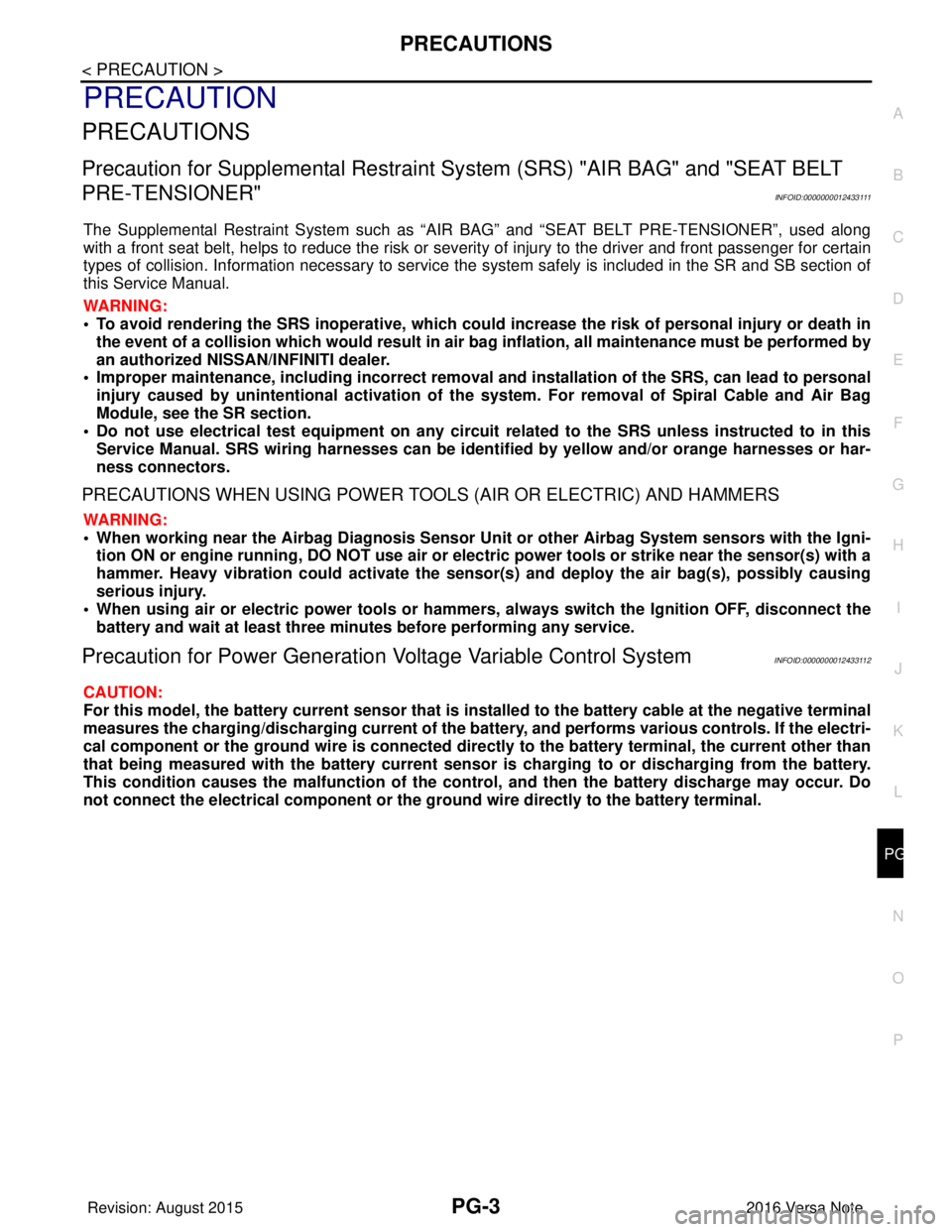
Precaution for Power Generation Voltage Variable Control SystemINFOID:0000000012433112
CAUTION:
For this model, the battery current sensor that is in stalled to the battery cable at the negative terminal
measures the charging/discharging current of the battery, and performs various controls. If the electri-
cal component or the ground wire is connected direct ly to the battery terminal, the current other than
that being measured with the battery current sensor is charging to or discharging from the battery.
This condition causes the malfunction of the control, and then the battery discharge may occur. Do
not connect the electrical component or the gr ound wire directly to the battery terminal.
Revision: August 2015 2016 Versa Note
cardiagn.com
Page 2636 of 3641

PG
HARNESSPG-49
< WIRING DIAGRAM >
C
DE
F
G H
I
J
K L
B A
O P
N
B3 F1 B/3 : Generator
D4 F28 — : Starter motor
B3 F2 — : Generator D3 F29 B/2 : Fuel injector no. 3 (Rear)
B4 F3 B/1 : A/C compressor D3 F30 B/2 : Fuel injector no. 4 (Rear)
B4 F4 — : Generator D1 F31 B/6 : Mass air flow sensor
B4 F5 — : Engine ground E1 F32 GR/2: Exhaust valve timing control solenoid
valve
E2 F6 GR/2 : Engine coolant temperature sensor F1 F33 W/6 : To E19
D1 F7 B/6 : Electric throttle control actuator B1 F34 GR/3: Ignition coil no.1 (With power
transistor)
E 1 F 8 W / 2 4 : To E 8 C 1 F 3 5 G R / 3: Ignition coil no.2 (With power
transistor)
F2 F9 GR/4 : Battery current sensor C1 F36 GR/3: Ignition coil no.3 (With power
transistor)
G 2 F 1 0 G R / 3 2 : E C M D 2 F 3 7 G R / 3: Ignition coil no.4 (With power
transistor)
G1 F11 BR/48 : ECM C4 F38 B/3 : Engine oil pressure sensor
D1 F12 BR/4 : Air fuel ratio (A/F) sensor 1 G3 F39 — : Fusible link box (Battery)
C3 F14 GR/2 : Knock sensor G3 F40 — : Fusible link box (Battery)
E1 F15 B/3 : Crankshaft position sensor (POS) G4 F41 B/3 : Output speed sensor
D4 F16 — : Engine ground F2 F42 W/12: IPDM E/R (Intelligent power distribution
module engine room)
B3 F17 B/2 : Fuel injector no. 1 (Front) F2 F43 W/12: IPDM E/R (Intelligent power distribution
module engine room)
C3 F18 B/2 : Fuel injector no. 2 (Front) F2 F44 B/48 : TCM (Transmission control module)
C3 F19 B/2 : Fuel injector no. 3 (Front) F4 F46 GR/22 : CVT unit
D3 F20 B/2 : Fuel injector no. 4 (Front) G4 F48 B/3 : Secondary speed sensor
D2 F21 B/3 : Camshaft position sensor G4 F50 B/3 : Primary speed sensor
C 1 F 2 2 G R / 2 : Evap canister purge volume control
solenoid valve F3 F52 B/10 : Transmission range switch
B 3 F 2 3 G R / 2 : Intake valve timing control solenoid
valve
B3 F53 B/2 : Fuel injector no. 1 (Rear)
E4 F24 G/3 : Park/neutral position (PNP) switch C3 F54 B/2 : Fuel injector no. 2 (Rear)
C4 F25 GR/2 : Engine oil temperature sensor G1 F55 GR/12 : To E55
C 3 F 2 6 W / 2 : C o n d e n s e r D 2 F 5 6 B / 3: Exhaust valve timing control position
sensor
D 3 F 2 7 — : S t a r t e r m o t o r D 3 F 5 9 — : E n g i n e g r o u n d
Revision: August 2015 2016 Versa Note
cardiagn.com
Page 2660 of 3641
PG
BATTERY CURRENT SENSORPG-73
< REMOVAL AND INSTALLATION >
C
DE
F
G H
I
J
K L
B A
O P
N
BATTERY CURRENT SENSOR
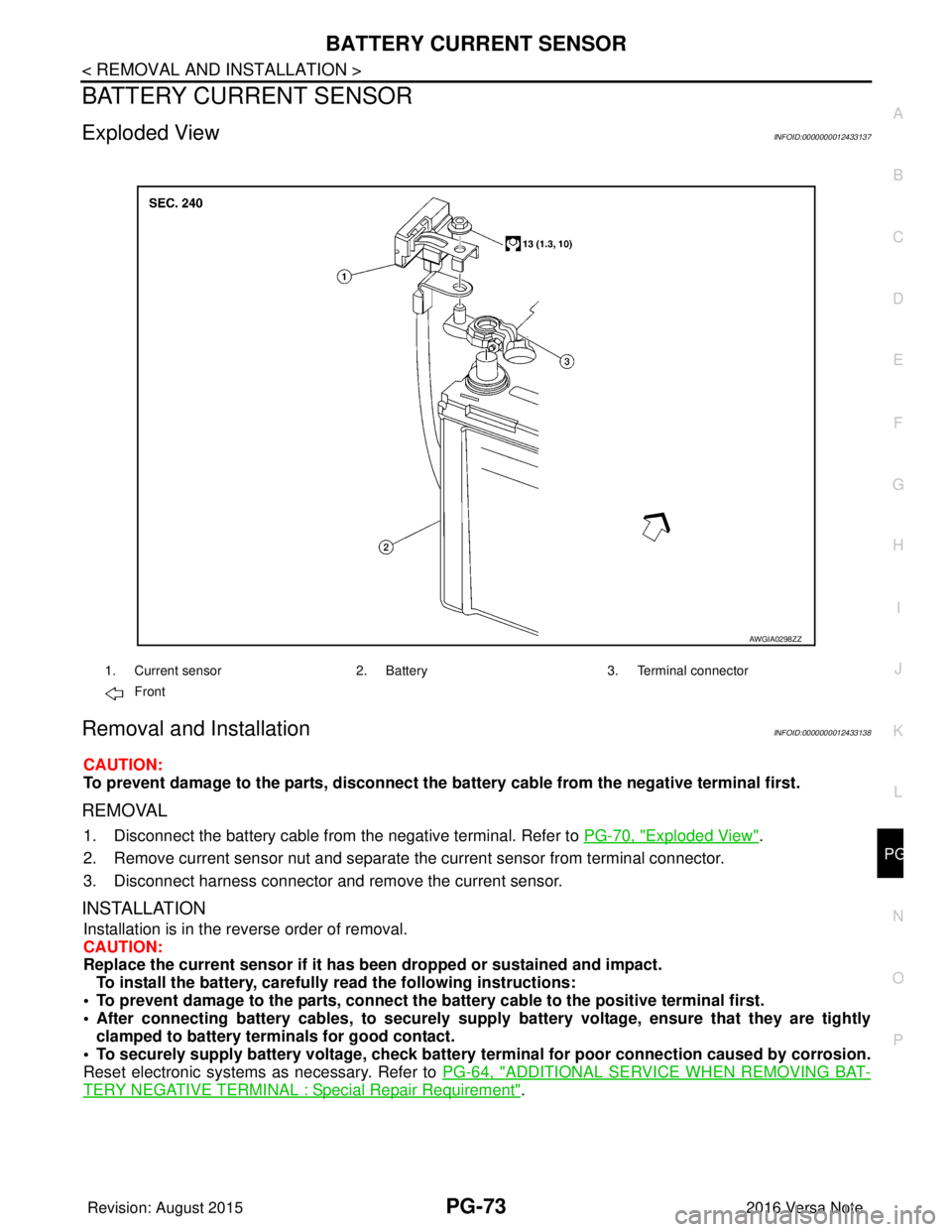
Exploded ViewINFOID:0000000012433137
Removal and InstallationINFOID:0000000012433138
CAUTION:
To prevent damage to the parts, disconnect the battery cable from the negative terminal first.
REMOVAL
1. Disconnect the battery cable from
the negative terminal. Refer to PG-70, "Exploded View".
2. Remove current sensor nut and separate the current sensor from terminal connector.
3. Disconnect harness connector and remove the current sensor.
INSTALLATION
Installation is in the reverse order of removal.
CAUTION:
Replace the current sensor if it has b een dropped or sustained and impact.
To install the battery, carefully read the following instructions:
• To prevent damage to the parts, connect the battery cable to the positive terminal first.
• After connecting battery cables, to securely supp ly battery voltage, ensure that they are tightly
clamped to battery terminals for good contact.
• To securely supply battery voltage, check battery terminal for poor connection caused by corrosion.
Reset electronic systems as necessary. Refer to PG-64, "
ADDITIONAL SERVICE WHEN REMOVING BAT-
TERY NEGATIVE TERMINAL : Special Repair Requirement".
AWGIA0298ZZ
1. Current sensor2. Battery3. Terminal connector
Front
Revision: August 2015 2016 Versa Note
cardiagn.com
Page 3033 of 3641
SRC-16
< SYSTEM DESCRIPTION >
DIAGNOSIS SYSTEM (AIR BAG)
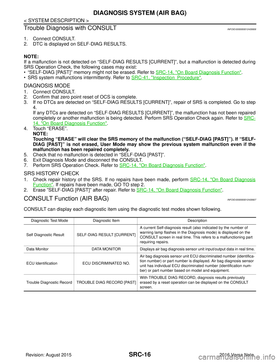
Trouble Diagnosis with CONSULT
INFOID:0000000012430606
1. Connect CONSULT.
2. DTC is displayed on SELF-DIAG RESULTS.
NOTE:
If a malfunction is not detected on “SELF-DIAG RESULTS [CURRENT]”, but a malfunction is detected during
SRS Operation Check, the following cases may exist:
• “SELF-DIAG [PAST]” memory might not be erased. Refer to SRC-14, "
On Board Diagnosis Function".
• SRS system malfunctions intermittently. Refer to SRC-41, "
InspectionProcedure".
DIAGNOSIS MODE
1. Connect CONSULT.
2. Confirm that zero point reset of OCS is complete.
3. If no DTCs are detected on “SELF-DIAG RESULTS [CURRE NT]”, repair of SRS is completed. Go to step
4.
If any DTCs are detected on “SELF-DIAG RESULT S [CURRENT]”, the malfunction has not been repaired
completely or another malfunction is being detected. Perform SRS Operation Check again. Refer to SRC-
14, "On Board Diagnosis Function".
4. Touch “ERASE”. NOTE:
Touching “ERASE” will clear the SRS memory of the malfunction (“SELF-DIAG [PAST]”). If “SELF-
DIAG [PAST]” is not erased, User Mode may sh ow the previous system malfunction even if the
malfunction has been repaired completely.
5. Check that no malfunction is det ected in “SELF-DIAG [PAST]”.
6. Exit Diagnosis Mode and disconnect the CONSULT.
7. Perform SRS Operation Check. Refer to SRC-14, "
On Board Diagnosis Function".
SRS HISTORY CHECK
1. Check repair history of the SRS. If no repairs have been made, perform SRC-14, "On Board Diagnosis
Function". If repairs have been made, GO TO step 2.
2. Erase ”SELF-DIAG [PAST]” after repair. Refer to SRC-14, "
On Board Diagnosis Function".
CONSULT Function (AIR BAG)INFOID:0000000012430607
CONSULT can display each diagnostic item using the diagnostic test modes shown following.
Diagnostic Test ModeDiagnostic Item Description
Self Diagnostic Result SEL F-DIAG RESULT [CURRENT]A current Self-diagnosis result (also indicated by the number of
warning lamp flashes in the Diagnosis mode) is displayed on the
CONSULT screen in real time. This refers to a malfunctioning part
requiring repairs.
Data Monitor DATA MONITOR Displays air bag diagnosis sensor unit input/output data in real time.
ECU Identification ECU DISCRIMINATED NO. Air bag diagnosis sensor unit ECU discriminated number (identifica-
tion number) or part number is displayed. Air bag diagnosis sensor
unit has individual ECU discriminated number (identification num-
ber) or part number based on model and equipment.
Trouble Diagnostic Record TR OUBLE DIAG RECORD [PAST] With TROUBLE DIAG RECORD, diagnosis results previously
erased by a reset operation can be displayed on the CONSULT
screen.
Revision: August 2015
2016 Versa Note
cardiagn.com