2016 NISSAN NOTE start
[x] Cancel search: startPage 2685 of 3641

PWC-24
< BASIC INSPECTION >
DIAGNOSIS AND REPAIR WORK FLOW
>> GO TO 2.
2. CONFIRM THE SYMPTOM
Check the malfunction on the vehicle that the customer describes.
Inspect the relation of the symptoms and the condition when the symptoms occur.
>> GO TO 3.
3. IDENTIFY THE MALFUNCTIONING S YSTEM WITH SYMPTOM DIAGNOSIS
Use Symptom diagnosis from the symptom inspection result in step 2 and then identify where to start perform-
ing the diagnosis based on possible causes and symptoms.
>> GO TO 4.
4. PERFORM THE COMPONENT DIAGNOSIS OF THE OF THE APPLICABLE SYSTEM
Perform the diagnosis with Component diagnosis of the applicable system.
>> GO TO 5.
5. REPAIR OR REPLACE THE MALFUNCTIONING PARTS
Repair or replace the specified malfunctioning parts.
>> GO TO 6.
6. FINAL CHECK
Check that malfunctions are not reproduced when obtaini ng the malfunction information from the customer,
referring to the symptom inspection result in step 2.
Are the malfunctions corrected?
YES >> Inspection End.
NO >> GO TO 3.
Revision: August 2015 2016 Versa Note
cardiagn.com
Page 2687 of 3641

PWC-26
< DTC/CIRCUIT DIAGNOSIS >
POWER SUPPLY AND GROUND CIRCUIT
1.CHECK FUSES AND FUSIBLE LINK
Check that the following fuses and fusible link are not blown.
Is the fuse blown?
YES >> Replace the blown fuse or fusible link after repairing the affected circuit.
NO >> GO TO 2.
2.CHECK POWER SUPPLY CIRCUIT
1. Turn ignition switch OFF.
2. Disconnect BCM connectors.
3. Check voltage between BCM connector and ground.
Is the inspection result normal?
YES >> GO TO 3.
NO >> Repair harness or connector.
3.CHECK GROUND CIRCUIT
Check continuity between BCM connector and ground.
Is the inspection result normal?
YES >> Inspection End.
NO >> Repair harness or connector.
POWER WINDOW MAIN SWITCH
POWER WINDOW MAIN SWITCH : Diagnosis ProcedureINFOID:0000000012431810
Regarding Wiring Diagram information, refer to PWC-16, "Wiring Diagram".
1.CHECK MAIN POWER WINDOW AND DOOR LOCK/UNLOCK SWITCH POWER SUPPLY
1. Turn ignition switch OFF.
2. Disconnect main power window and door lock/unlock switch connector.
3. Check voltage between main power window and door lock/unlock switch harness connector and ground.
Terminal No. Signal nameFuses and fusible link No.
37 Battery power supply 8 (10A)
42 12 (10A)
50 G (40A)
11 Ignition switch ACC or ON 18 (10A)
38 Ignition switch ON or START 2 (10A)
BCMGround Ignition switch position
Connector Terminal
—OFF
ACC ON
M18 11
0 V
Battery voltage
Battery voltage
37
Battery voltage
38 0 V0 V
M19 42
Battery voltage Battery voltage
50
BCM GroundContinuity
Connector Terminal
M19 55—Yes
Revision: August 2015 2016 Versa Note
cardiagn.com
Page 2751 of 3641

WT-8
< SYSTEM DESCRIPTION >
SYSTEM
SYSTEM
TIRE PRESSURE MONITORING SYSTEM
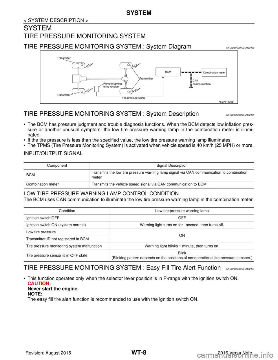
TIRE PRESSURE MONITORING SYSTEM : System DiagramINFOID:0000000012432432
TIRE PRESSURE MONITORING SY STEM : System DescriptionINFOID:0000000012432433
• The BCM has pressure judgment and trouble diagnosis functions. When the BCM detects low inflation pres-
sure or another unusual symptom, the low tire pressure warning lamp in the combination meter is illumi-
nated.
• If the tire pressure is less than the specified value, the low tire pressure warning lamp illuminates.
• The TPMS (Tire Pressure Monitoring System) is activated when vehicle s peed is 40 km/h (25 MPH) or more.
INPUT/OUTPUT SIGNAL
LOW TIRE PRESSURE WARNING LAMP CONTROL CONDITION
The BCM uses CAN communication to illuminate the low tire pressure warning lamp in the combination meter.
TIRE PRESSURE MONITORING SYSTEM : Easy Fill Tire Alert FunctionINFOID:0000000012432434
• This function operates only when the selector lever position is in P-range with the ignition switch ON.
CAUTION:
Never start the engine.
NOTE:
The easy fill tire alert function is reco mmended to use with the ignition switch ON.
ALEIA0133GB
Component Signal Description
BCM Transmits the low tire pressure warning lamp signal via CAN communication to combination
meter.
Combination meter Transmits the vehicle speed signal via CAN communication to BCM.
Condition Low tire pressure warning lamp
Ignition switch OFF OFF
Ignition switch ON (system normal) Warning light turns on for 1second, then turns off.
Low tire pressure ON
Transmitter ID not registered in BCM.
Tire pressure monitoring system malfunction Warning light blinks 1 minute, then turns on.
Tire pressure sensor is in OFF state Blink
(Blinking pattern depends on the positions of nonoperational tire pressure sensors.)
Revision: August 2015 2016 Versa Note
cardiagn.com
Page 2752 of 3641

SYSTEMWT-9
< SYSTEM DESCRIPTION >
C
DF
G H
I
J
K L
M A
B
WT
N
O P
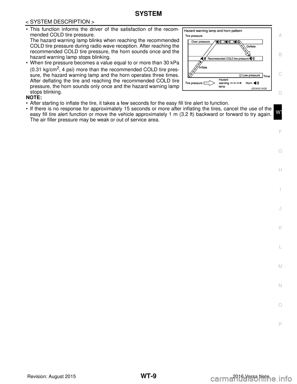
• This function informs the driver of the satisfaction of the recom- mended COLD tire pressure.
The hazard warning lamp blinks when reaching the recommended
COLD tire pressure during radio wave reception. After reaching the
recommended COLD tire pressure, the horn sounds once and the
hazard warning lamp stops blinking.
• When tire pressure becomes a value equal to or more than 30 kPa
(0.31 kg/cm
2, 4 psi) more than the recommended COLD tire pres-
sure, the hazard warning lamp and the horn operates three times.
After deflating the tire and reaching the recommended COLD tire
pressure, the horn sounds only once and the hazard warning lamp
stops blinking.
NOTE:
• After starting to inflate the tire, it takes a fe w seconds for the easy fill tire alert to function.
• If there is no response for approximately 15 seconds or mo re after inflating the tires, cancel the use of the
easy fill tire alert function or move the vehicle approximately 1 m (3.2 ft) backward or forward to try again.
The air filler pressure may be weak or out of service area.
JSEIA0214GB
Revision: August 2015 2016 Versa Note
cardiagn.com
Page 2765 of 3641

WT-22
< BASIC INSPECTION >
ID REGISTRATION PROCEDURE
ID REGISTRATION PROCEDURE
DescriptionINFOID:0000000012432443
This procedure must be performed after replacing wheels, transmitters or the BCM.
Work ProcedureINFOID:0000000012432444
TPMS ID registration can be performed using one of the following procedures:
• Transmitter Activation tool [KV48105501 (J-45295-A)] with CONSULT (preferred method)
• Signal Tech II tool [- (J- 50190)] with CONSULT (preferred method)
• Signal Tech II tool [- (J-50190)] without CONSULT
• CONSULT only
TPMS REGISTRATION WITH TRANSMITTER ACTIVATION TOOL [KV48105501 (J-45295-A)]
With CONSULT
1. Turn the ignition switch ON.
2. Using CONSULT, select “WORK SUPPORT” in “AIR PRESSURE MONITOR” of “BCM”. Then, select “ID
REGIST.”
3. Select “Start” on “ID REGIST” screen.
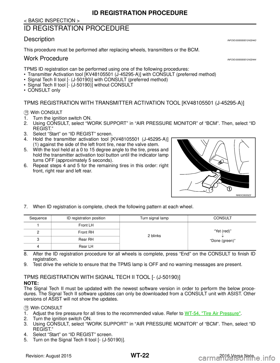
4. Hold the transmitter activation tool [KV48105501 (J-45295-A)] (1) against the side of the left front tire, near the valve stem.
5. With the tool held at a 0 to 15 degree angle to the tire, press and hold the transmitter activation tool button until the indicator lamp
turns OFF (approximately 5 seconds).
6. Repeat steps 4 and 5 for the remaining tires in this order: right front, right rear and left rear.
7. When ID registration is complete, check the following pattern at each wheel.
8. After the ID registration procedure for all wheels is complete, press “End” on the CONSULT to finish ID registration.
9. Test drive the vehicle to ensure that the TPMS lamp is OFF and no warning messages are present.
TPMS REGISTRATION WITH SIGNAL TECH II TOOL [- (J-50190)]
NOTE:
The Signal Tech II must be updated with the newest software version in order to perform the below proce-
dures. The Signal Tech II software updates can onl y be downloaded from a CONSULT unit with ASIST. Other
versions of ASIST wil l not show the updates.
With CONSULT
1. Adjust the tire pressure for all tires to the recommended value. Refer to WT-54, "Tire Air Pressure".
2. Turn the ignition switch ON.
3. Using CONSULT, select “WORK SUPPORT” in “AIR PRESSURE MONITOR” of “BCM”. Then, select “ID
REGIST.”
4. Select “Start” on “ID REGIST” screen.
5. Turn on the Signal Tech II tool [- (J-50190)].
NNEIC0020ZZ
Sequence ID registration position Turn signal lamp CONSULT
1F ro nt L H
2 blinks “Yet (red)”
↓
“Done (green)”
2F
ro nt R H
3R ea r R H
4R ear L H
Revision: August 2015 2016 Versa Note
cardiagn.com
Page 2767 of 3641

WT-24
< BASIC INSPECTION >
ID REGISTRATION PROCEDURE
2. Turn the ignition switch ON.
3. Using CONSULT, select “WORK SUPPORT” in “AIR PRESSURE MONITOR” of “BCM”. Then, select “ID
REGIST.”
4. Select “Start” on “ID REGIST” screen.
5. Drive the vehicle at a speed greater than 40 km/h (25 MPH) for 3 minutes or more.
6. After ID registration for all wheels is complete, press “End” on the CONSULT to finish ID registration.
7. Adjust the tire pressures for all tires to the recommended value. Refer to WT-54, "
Tire Air Pressure".
8. Test drive the vehicle to ensure that the TPMS lamp is OFF and no warning messages are present.
ID registration position CONSULT
Front LH “Yet (red)”↓
“Done (green)”
Front RH
Rear RHRear LH
Revision: August 2015 2016 Versa Note
cardiagn.com
Page 2778 of 3641

POWER SUPPLY AND GROUND CIRCUITWT-35
< DTC/CIRCUIT DIAGNOSIS >
C
DF
G H
I
J
K L
M A
B
WT
N
O P
Is the fuse blown?
YES >> Replace the blown fuse or fusible link after repairing the affected circuit.
NO >> GO TO 2.
2.CHECK POWER SUPPLY CIRCUIT
1. Turn ignition switch OFF.
2. Disconnect BCM connectors.
3. Check voltage between BCM connector and ground.
Is the inspection result normal?
YES >> GO TO 3.
NO >> Repair harness or connector.
3.CHECK GROUND CIRCUIT
Check continuity between BCM connector and ground.
Is the inspection result normal?
YES >> Inspection End.
NO >> Repair harness or connector.
Terminal No. Signal nameFuses and fusible link No.
37 Battery power supply 8 (10A)
42 12 (10A)
50 G (40A)
11 Ignition switch ACC or ON 18 (10A)
38 Ignition switch ON or START 2 (10A)
BCMGround Ignition switch position
Connector Terminal
—OFF
ACC ON
M18 11
0 V
Battery voltage
Battery voltage
37
Battery voltage
38 0 V0 V
M19 42
Battery voltage Battery voltage
50
BCM GroundContinuity
Connector Terminal
M19 55—Yes
Revision: August 2015 2016 Versa Note
cardiagn.com
Page 2783 of 3641

WT-40
< SYMPTOM DIAGNOSIS >
EASY FILL TIRE ALERT DOES NOT ACTIVATE
EASY FILL TIRE ALERT DOES NOT ACTIVATE
DescriptionINFOID:0000000012432461
The easy fill tire alert does not function while inflating a tire when the select lever position is in P-range with the
ignition switch ON.
NOTE:
• After starting to inflate the tire, it takes a few seconds for the easy fill tire alert to function.
• If there is no response for approximately 15 seconds or mo re after inflating the tires, cancel the use of the
easy fill tire alert function or move the vehicle approximately 1 m (3.2 ft) backward or forward to try again.
The air filler pressure may be weak or out of service area.
• For easy fill tire alert, Refer to WT-8, "
TIRE PRESSURE MONITORING SYST EM : Easy Fill Tire Alert Func-
tion".
Diagnosis ProcedureINFOID:0000000012432462
1. LOCATION CHANGE
Move the vehicle to other area and repeat the procedure of the easy fill tire alert function. Refer to WT-8,
"TIRE PRESSURE MONITORING SYSTEM : Easy Fill Tire Alert Function".
Is the function normal?
YES >> Normal (the easy fill tire alert may not operate, depending on reception condition.)
NO >> GO TO 2.
2.PERFORM BCM SELF-DIAGNOSIS
With CONSULT
Perform self-diagnosis for “AIR PRESSURE MONITOR”.
Is any DTC detected?
YES >> Perform trouble diagnosis for detected DTC. Refer to BCS-50, "DTCIndex" (with Intelligent Key
system) or BCS-115, "
DTCIndex" (without Intelligent Key system).
NO >> GO TO 3.
3.CHECK HAZARD WARNING LAMP OPERATION
Check hazard warning lamp operation with hazard switch.
Does the hazard warning lamp blink?
YES >> GO TO 4.
NO >> Perform trouble diagnosis for the hazard warning lamp. Refer to EXL-85, "
Diagnosis Procedure" .
4.PERFORM TCM SELF-DIAGNOSIS
With CONSULT
Perform self-diagnosis for “TRANSMISSION”.
Is any DTC detected?
YES >> Check malfunctioning circuit. Refer to TM-110, "DTC Index".
NO >> GO TO 5.
5.CHECK HORN OPERATION
Check horn operation. Refer to HRN-3, "
Wiring Diagram".
Is the operation normal?
YES >> GO TO 6.
NO >> Repair or replace error-detected parts.
6.PERFORM BCM SELF-DIAGNOSIS
With CONSULT
1. Drive for 10 minutes at a speed of 40 km/h (25 MPH) or more.
CAUTION:
Total time driving at a speed of 40 km/h (25 MPH) or more must be 10 minutes.
2. Stop the vehicle.
3. Perform self-diagnosis for “AIR PRESSURE MONITOR”.
Revision: August 2015 2016 Versa Note
cardiagn.com