2016 NISSAN NOTE start
[x] Cancel search: startPage 2541 of 3641
![NISSAN NOTE 2016 Service Repair Manual PCS-38
< SYSTEM DESCRIPTION >[POWER DISTRIBUTION SYSTEM]
DIAGNOSIS SYSTEM (BCM)
INTELLIGENT KEY
INTELLIGENT KEY : CONSULT Function (BCM - INTELLIGENT KEY)INFOID:0000000012542492
SELF DIAGNOSTIC RESULT NISSAN NOTE 2016 Service Repair Manual PCS-38
< SYSTEM DESCRIPTION >[POWER DISTRIBUTION SYSTEM]
DIAGNOSIS SYSTEM (BCM)
INTELLIGENT KEY
INTELLIGENT KEY : CONSULT Function (BCM - INTELLIGENT KEY)INFOID:0000000012542492
SELF DIAGNOSTIC RESULT](/manual-img/5/57363/w960_57363-2540.png)
PCS-38
< SYSTEM DESCRIPTION >[POWER DISTRIBUTION SYSTEM]
DIAGNOSIS SYSTEM (BCM)
INTELLIGENT KEY
INTELLIGENT KEY : CONSULT Function (BCM - INTELLIGENT KEY)INFOID:0000000012542492
SELF DIAGNOSTIC RESULT
Refer to
BCS-50, "DTCIndex".
DATA MONITOR
ACTIVE TEST
Monitor Item [Unit] Main Description
REQ SW -DR [On/Off] ×Indicates condition of door request switch LH.
REQ SW -AS [On/Off] ×Indicates condition of door request switch RH.
REQ SW -BD/TR [On/Off] ×Indicates condition of back door request switch.
PUSH SW [On/Off] Indicates condition of push-button ignition switch.
CLUCH SW [On/Off] ×Indicates condition of clutch interlock switch.
BRAKE SW 1 [On/Off] ×Indicates condition of brake switch.
BRAKE SW 2 [On/Off] Indicates condition of brake switch.
DETE/CANCL SW [On/Off] ×Indicates condition of P (park) position.
SFT PN/N SW [On/Off] ×Indicates condition of P (park) or N (neutral) position.
UNLK SEN -DR [On/Off] ×Indicates condition of door unlock sensor.
PUSH SW -IPDM [On/Off] Indicates condition of push-button ignition switch received from IPDM E/R on
CAN communication line.
IGN RLY1 -F/B [On/Off] Indicates condition of ignition relay 1 received from IPDM E/R on CAN commu-
nication line.
DETE SW -IPDM [On/Off] Indicates condition of detent switch received from TCM on CAN communication
line.
SFT PN -IPDM [On/Off] Indicates condition of P (park) or N (neutral) position from TCM on CAN com-
munication line.
SFT P -MET [On/Off] Indicates condition of P (park) position from TCM on CAN communication line.
SFT N -MET [On/Off] Indicates condition of N (neutral) position from IPDM E/R on CAN communica-
tion line.
ENGINE STATE [Stop/Start/Crank/Run] ×Indicates condition of engine state from ECM on CAN communication line.
VEH SPEED 1 [mph/km/h] ×Indicates condition of ve
hicle speed signal receiv ed from ABS on CAN commu-
nication line.
VEH SPEED 2 [mph/km/h] ×Indicates condition of vehicle speed signal received from combination meter on
CAN communication line.
DOOR STAT -DR [LOCK/READY/UNLK] ×Indicates condition of driver side door status.
DOOR STAT -AS [LOCK/READY/UNLK] ×Indicates condition of passenger side door status.
ID OK FLAG [Set/Reset] Indicates condition of Intelligent Key ID.
PRMT ENG STRT [Set/Reset] Indicates condition of engine start possibility.
RKE OPE COUN1 [0-19] ×When remote keyless entry receiver receives the signal transmitted while oper-
ating on Intelligent Key, the numerical value start changing.
RKE OPE COUN2 [0-19] ×When remote keyless entry receiver receives the signal transmitted while oper-
ating on Intelligent Key, the numerical value start changing.
RKE-LOCK [On/Off] Indicates condition of lock signal from Intelligent Key.
RKE-UNLOCK [On/Off] Indicates condition of unlock signal from Intelligent Key.
RKE-PANIC [On/Off] Indicates condition of panic signal from Intelligent Key.
RKE-MODE CHG [On/Off] Indicates condition of mode change signal from Intelligent Key.
Revision: August 2015 2016 Versa Note
cardiagn.com
Page 2542 of 3641
![NISSAN NOTE 2016 Service Repair Manual PCS
DIAGNOSIS SYSTEM (BCM)PCS-39
< SYSTEM DESCRIPTION > [POWER DISTRIBUTION SYSTEM]
C
D
E
F
G H
I
J
K L
B A
O P
N
WORK SUPPORT
Test Item
Description
INSIDE BUZZER This test is able to check combinatio NISSAN NOTE 2016 Service Repair Manual PCS
DIAGNOSIS SYSTEM (BCM)PCS-39
< SYSTEM DESCRIPTION > [POWER DISTRIBUTION SYSTEM]
C
D
E
F
G H
I
J
K L
B A
O P
N
WORK SUPPORT
Test Item
Description
INSIDE BUZZER This test is able to check combinatio](/manual-img/5/57363/w960_57363-2541.png)
PCS
DIAGNOSIS SYSTEM (BCM)PCS-39
< SYSTEM DESCRIPTION > [POWER DISTRIBUTION SYSTEM]
C
D
E
F
G H
I
J
K L
B A
O P
N
WORK SUPPORT
Test Item
Description
INSIDE BUZZER This test is able to check combination meter warning chime operation [Take Out/Knob/Key/
Off].
LCD This test is able to check combination me
ter display information [Off/LK WN/OUTKEY/NO
KY/BATT/INSRT/SFT P/ROTAT/ID NG/B&P I/B&P N].
BATTERY SAVER This test is able to check battery saver operation [On/Off].
ENGINE SW ILLUMI This test is able to check push-button ignition switch START indicator operation [On/Off].
PUSH SWITCH INDICATOR This test is able to check push-button ignition switch indicator operation [On/Off].
INT LAMP This test is able to check interior room lamp operation [On/Off].
INDICATOR This test is able to check combination mete r warning lamp operation [KEY ON/KEY IND/Off].
FLASHER This test is able to check hazard lamp operation [LH/RH/Off].
OUTSIDE BUZZER This test is able to check Intelligent Key warning buzzer operation [On/Off].
HORN This test is able to check horn operation [On].
P RANGE This test is able to check CVT shift selector illumination operation [On/Off].
Support ItemSetting Description
LOCK/UNLOCK BY I-KEY On*
Door lock/unlock function from Intelligent Key ON.
Off Door lock/unlock function from Intelligent Key OFF.
ANTI KEY LOCK IN FUNCTI On*
Anti lock out setting ON.
Off Anti lock out setting OFF.
ANS BACK I-KEY UNLOCK Off
No buzzer reminder when doors are unlocked with request switch.
On* Buzzer reminder when doors are unlocked with request switch.
ANS BACK I-KEY LOCK Horn Chirp
Horn chirp reminder when doors are locked with request switch.
Buzzer* Buzzer reminder when doors are locked with request switch.
Off No reminder when doors are locked with request switch.
HORN WITH KEYLESS LOCK Off
Horn chirp reminder when doors are locked with Intelligent Key.
On* No horn chirp reminder when doors are locked with Intelligent Key.
HAZARD ANSWER BACK Lock/Unlock*
Hazard warning lamp activation when doors are locked/unlocked
with Intelligent Key or request switch.
Unlock Only Hazard warning lamp activation when doors are unlocked with Intel-
ligent Key or request switch.
Lock Only Hazard warning lamp activation when doors are locked with Intelli-
gent Key or request switch.
Off No hazard warning lamp activation when doors are locked/unlocked
with Intelligent Key or request switch.
INSIDE ANT DIAGNOSIS —This function allo ws inside key antenna self-diagnosis.
CONFIRM KEY FOB ID —Intelligent Key ID code can be checked.
SHORT CRANKING OUTPUT Start70 msec
Starter motor operation duration time setting.
100 msec
200 msec
End —
PANIC ALARM SET MODE 3 1.5 sec
Intelligent Key panic alarm button setting.
MODE 2 OFF
MODE 1* 0.5 sec
LO- BATT OF KEY FOB WARN On*
Intelligent Key low battery warning ON.
Off Intelligent Key low battery warning OFF.
Revision: August 2015 2016 Versa Note
cardiagn.com
Page 2578 of 3641
![NISSAN NOTE 2016 Service Repair Manual PCS
PUSH-BUTTON IGNITION SWITCH DOES NOT OPERATEPCS-75
< SYMPTOM DIAGNOSIS > [POWER DISTRIBUTION SYSTEM]
C
D
E
F
G H
I
J
K L
B A
O P
N
SYMPTOM DIAGNOSIS
PUSH-BUTTON IGNITION SW
ITCH DOES NOT OPERATE
D NISSAN NOTE 2016 Service Repair Manual PCS
PUSH-BUTTON IGNITION SWITCH DOES NOT OPERATEPCS-75
< SYMPTOM DIAGNOSIS > [POWER DISTRIBUTION SYSTEM]
C
D
E
F
G H
I
J
K L
B A
O P
N
SYMPTOM DIAGNOSIS
PUSH-BUTTON IGNITION SW
ITCH DOES NOT OPERATE
D](/manual-img/5/57363/w960_57363-2577.png)
PCS
PUSH-BUTTON IGNITION SWITCH DOES NOT OPERATEPCS-75
< SYMPTOM DIAGNOSIS > [POWER DISTRIBUTION SYSTEM]
C
D
E
F
G H
I
J
K L
B A
O P
N
SYMPTOM DIAGNOSIS
PUSH-BUTTON IGNITION SW
ITCH DOES NOT OPERATE
DescriptionINFOID:0000000012433320
Check that vehicle Operating Conditions are as listed in “Conditions of Vehicle” below before starting Diagno-
sis Procedure. Make sure to chec k each symptom in Diagnosis Procedure.
NOTE:
The engine start function, door lock function, power distribution system, and NATS-NVIS in the Intelligent Key
system are closely related to each other regarding c ontrol. The vehicle security function can operate only
when the door lock and power distribut ion system are operating normally.
Conditions of Vehicle (Operating Conditions)
• ENGINE START BY I-KEY in “Work support” is set to On. Refer to BCS-22, "INTELLIGENT KEY : CON-
SULT Function (BCM - INTELLIGENT KEY)".
• One or more of Intelligent Keys with registered Intelligent Key ID is in the vehicle.
Diagnosis ProcedureINFOID:0000000012433321
1.PERFORM WORK SUPPORT
Perform INSIDE ANT DIAGNOSIS in “Work Support” of “INTELLIGENT KEY” using CONSULT. Refer to BCS-
22, "INTELLIGENT KEY : CONSULT Func tion (BCM - INTELLIGENT KEY)".
>> GO TO 2.
2.PERFORM SELF DIAGNOSTIC RESULT
Perform “Self Diagnostic Result” of “BCM” using CONSULT.
Are any DTCs detected?
YES >> Refer to BCS-50, "DTCIndex".
NO >> GO TO 3.
3.CHECK PUSH-BUTTON IGNITION SWITCH
Check push-button ignition switch. Refer to PCS-71, "
Component Inspection".
Is the inspection result normal?
YES >> Refer to GI-42, "Intermittent Incident".
NO >> Repair or replace malfunctioning parts.
Revision: August 2015 2016 Versa Note
cardiagn.com
Page 2591 of 3641

PG-4
< PREPARATION >
PREPARATION
PREPARATION
PREPARATION
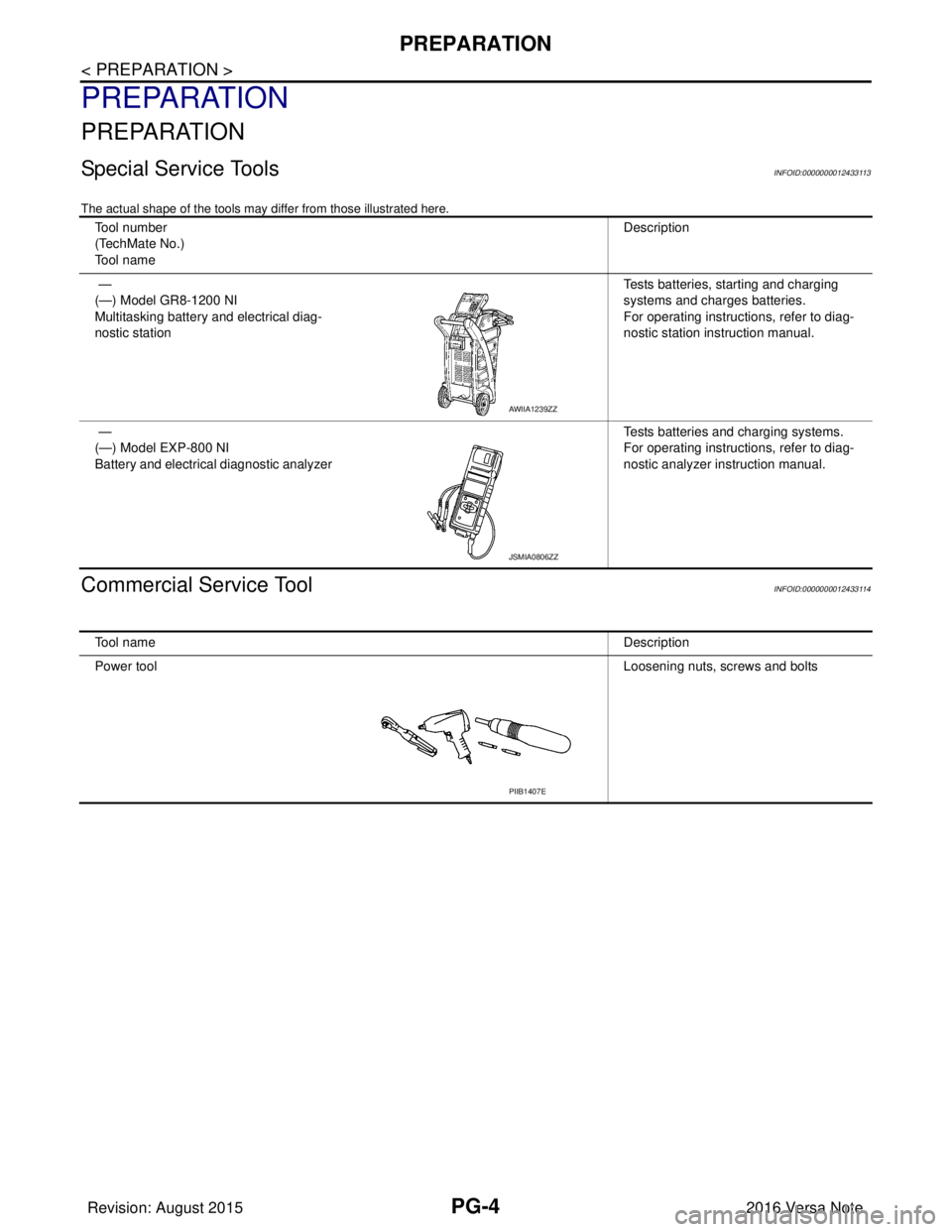
Special Service ToolsINFOID:0000000012433113
The actual shape of the tools may differ from those illustrated here.
Commercial Service ToolINFOID:0000000012433114
Tool number
(TechMate No.)
Tool nameDescription
—
(—) Model GR8-1200 NI
Multitasking battery and electrical diag-
nostic station Tests batteries, starting and charging
systems and charges batteries.
For operating instructions, refer to diag-
nostic station instruction manual.
—
(—) Model EXP-800 NI
Battery and electrical diagnostic analyzer Tests batteries and charging systems.
For operating instructions, refer to diag-
nostic analyzer instruction manual.
AWIIA1239ZZ
JSMIA0806ZZ
Tool name
Description
Power tool Loosening nuts, screws and bolts
PIIB1407E
Revision: August 2015 2016 Versa Note
cardiagn.com
Page 2632 of 3641

PG
HARNESSPG-45
< WIRING DIAGRAM >
C
DE
F
G H
I
J
K L
B A
O P
N
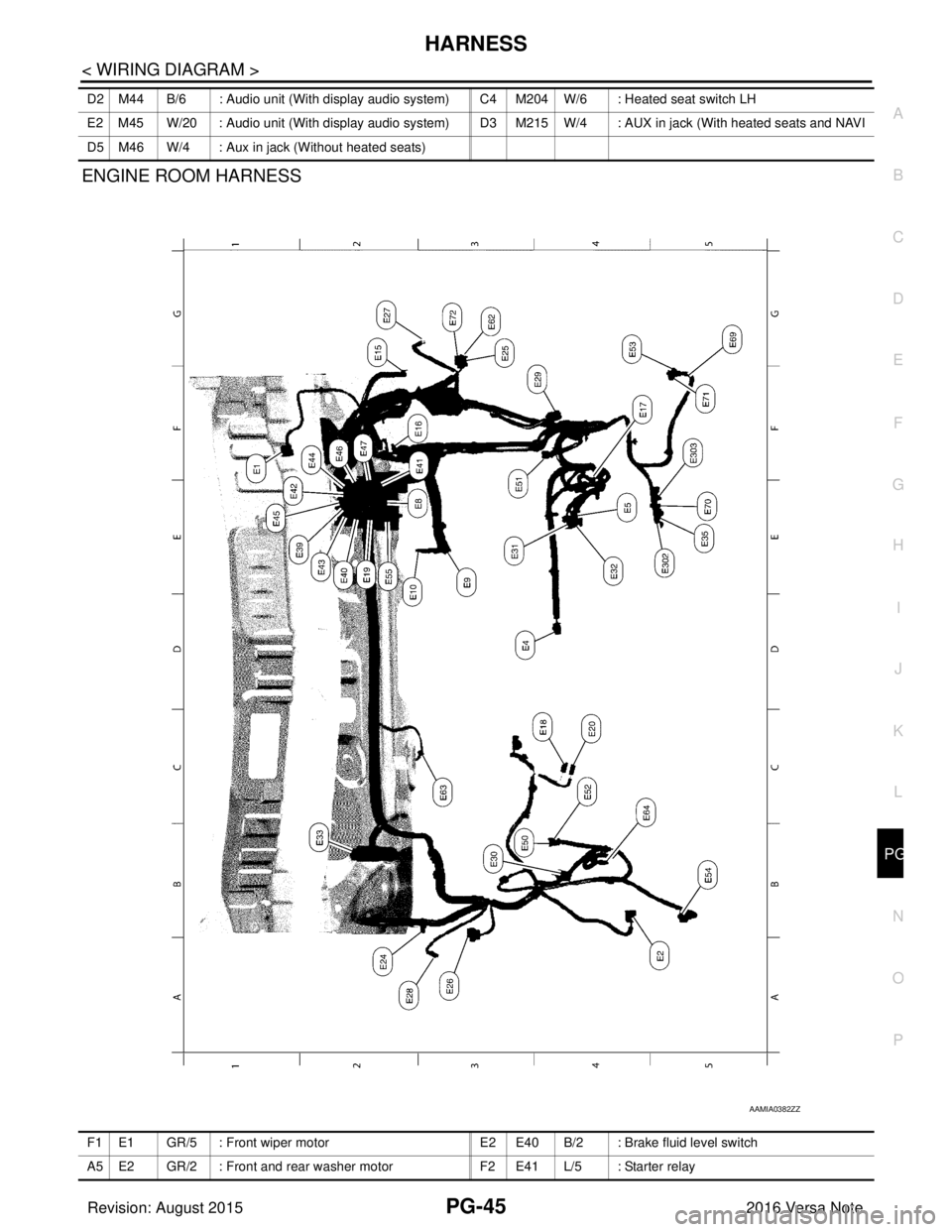
ENGINE ROOM HARNESS
D2 M44 B/6 : Audio unit (With display audio system) C4 M204
W/6 : Heated seat switch LH
E2 M45 W/20 : Audio unit (With display audio system) D3 M215 W/4 : AUX in jack (With heated seats and NAVI
D5 M46 W/4 : Aux in jack (Without heated seats)
AAMIA0382ZZ
F1 E1 GR/5 : Front wiper motor E2 E40 B/2 : Brake fluid level switch
A5 E2 GR/2 : Front and rear washer motor F2 E41 L/5 : Starter relay
Revision: August 2015 2016 Versa Note
cardiagn.com
Page 2636 of 3641

PG
HARNESSPG-49
< WIRING DIAGRAM >
C
DE
F
G H
I
J
K L
B A
O P
N
B3 F1 B/3 : Generator
D4 F28 — : Starter motor
B3 F2 — : Generator D3 F29 B/2 : Fuel injector no. 3 (Rear)
B4 F3 B/1 : A/C compressor D3 F30 B/2 : Fuel injector no. 4 (Rear)
B4 F4 — : Generator D1 F31 B/6 : Mass air flow sensor
B4 F5 — : Engine ground E1 F32 GR/2: Exhaust valve timing control solenoid
valve
E2 F6 GR/2 : Engine coolant temperature sensor F1 F33 W/6 : To E19
D1 F7 B/6 : Electric throttle control actuator B1 F34 GR/3: Ignition coil no.1 (With power
transistor)
E 1 F 8 W / 2 4 : To E 8 C 1 F 3 5 G R / 3: Ignition coil no.2 (With power
transistor)
F2 F9 GR/4 : Battery current sensor C1 F36 GR/3: Ignition coil no.3 (With power
transistor)
G 2 F 1 0 G R / 3 2 : E C M D 2 F 3 7 G R / 3: Ignition coil no.4 (With power
transistor)
G1 F11 BR/48 : ECM C4 F38 B/3 : Engine oil pressure sensor
D1 F12 BR/4 : Air fuel ratio (A/F) sensor 1 G3 F39 — : Fusible link box (Battery)
C3 F14 GR/2 : Knock sensor G3 F40 — : Fusible link box (Battery)
E1 F15 B/3 : Crankshaft position sensor (POS) G4 F41 B/3 : Output speed sensor
D4 F16 — : Engine ground F2 F42 W/12: IPDM E/R (Intelligent power distribution
module engine room)
B3 F17 B/2 : Fuel injector no. 1 (Front) F2 F43 W/12: IPDM E/R (Intelligent power distribution
module engine room)
C3 F18 B/2 : Fuel injector no. 2 (Front) F2 F44 B/48 : TCM (Transmission control module)
C3 F19 B/2 : Fuel injector no. 3 (Front) F4 F46 GR/22 : CVT unit
D3 F20 B/2 : Fuel injector no. 4 (Front) G4 F48 B/3 : Secondary speed sensor
D2 F21 B/3 : Camshaft position sensor G4 F50 B/3 : Primary speed sensor
C 1 F 2 2 G R / 2 : Evap canister purge volume control
solenoid valve F3 F52 B/10 : Transmission range switch
B 3 F 2 3 G R / 2 : Intake valve timing control solenoid
valve
B3 F53 B/2 : Fuel injector no. 1 (Rear)
E4 F24 G/3 : Park/neutral position (PNP) switch C3 F54 B/2 : Fuel injector no. 2 (Rear)
C4 F25 GR/2 : Engine oil temperature sensor G1 F55 GR/12 : To E55
C 3 F 2 6 W / 2 : C o n d e n s e r D 2 F 5 6 B / 3: Exhaust valve timing control position
sensor
D 3 F 2 7 — : S t a r t e r m o t o r D 3 F 5 9 — : E n g i n e g r o u n d
Revision: August 2015 2016 Versa Note
cardiagn.com
Page 2648 of 3641

PG
BATTERYPG-61
< BASIC INSPECTION >
C
DE
F
G H
I
J
K L
B A
O P
N
BASIC INSPECTION
BATTERY
How to Handle BatteryINFOID:0000000012433127
CAUTION:
• If it becomes necessary to start the engine with
a booster battery and jumper cables, use a 12-volt
booster battery.
• After connecting battery cables, ensure that they are tightly clamped to battery terminals for good
contact.
• Never add distilled water through the hole used to check specific gravity.
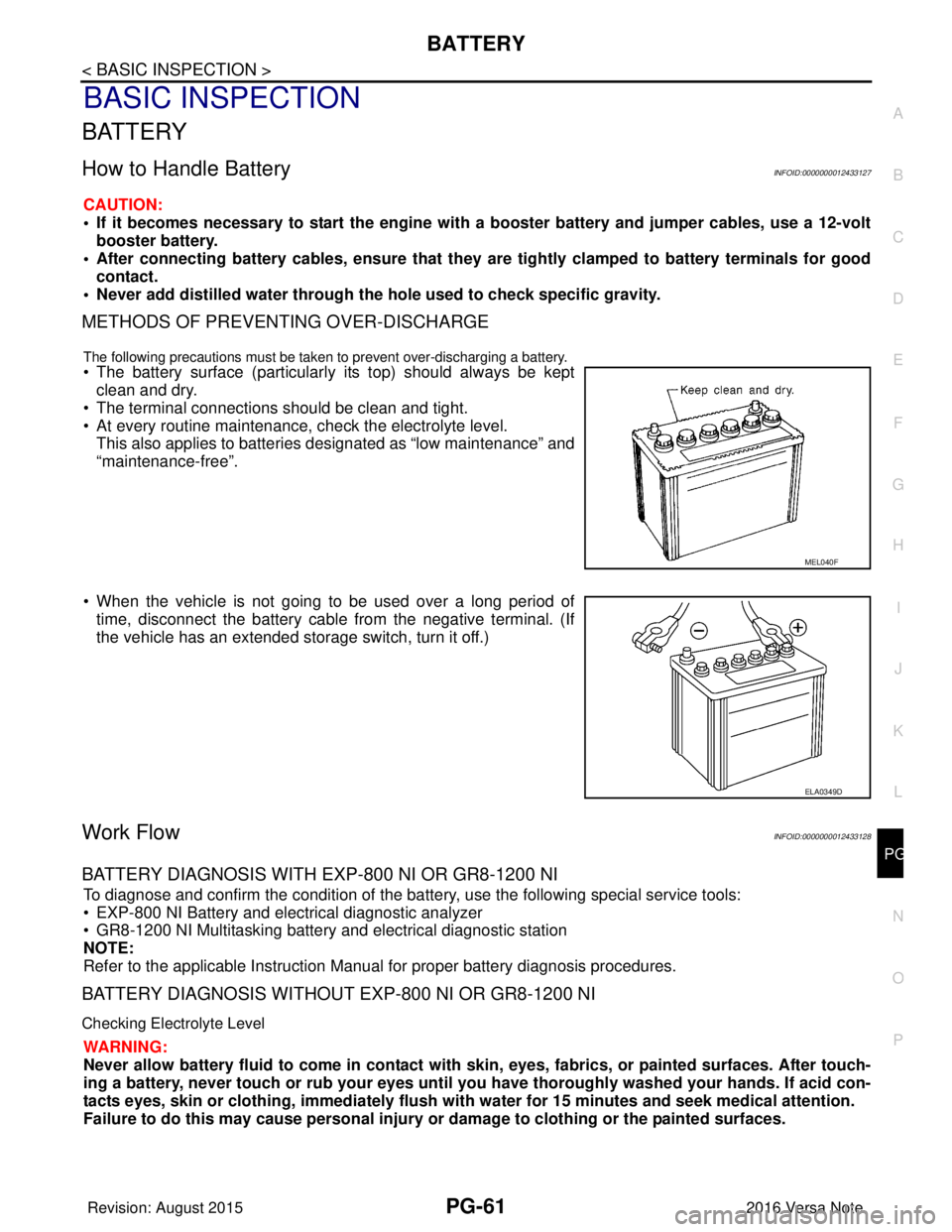
METHODS OF PREVENTING OVER-DISCHARGE
The following precautions must be taken to prevent over-discharging a battery.
• The battery surface (particularly its top) should always be kept
clean and dry.
• The terminal connections should be clean and tight.
• At every routine maintenance, check the electrolyte level. This also applies to batteries designated as “low maintenance” and
“maintenance-free”.
• When the vehicle is not going to be used over a long period of time, disconnect the battery cable from the negative terminal. (If
the vehicle has an extended storage switch, turn it off.)
Work FlowINFOID:0000000012433128
BATTERY DIAGNOSIS WITH EXP-800 NI OR GR8-1200 NI
To diagnose and confirm the condition of the batte ry, use the following special service tools:
• EXP-800 NI Battery and electrical diagnostic analyzer
• GR8-1200 NI Multitasking battery and electrical diagnostic station
NOTE:
Refer to the applicable Instruction Manual for proper battery diagnosis procedures.
BATTERY DIAGNOSIS WITHOUT EXP-800 NI OR GR8-1200 NI
Checking Electrolyte Level
WARNING:
Never allow battery fluid to come in contact with skin, eyes, fabrics, or painted surfaces. After touch-
ing a battery, never touch or rub your eyes until you have thoroughly washed your hands. If acid con-
tacts eyes, skin or clothing, imme diately flush with water for 15 minutes and seek medical attention.
Failure to do this may cause personal injury or damage to clothing or the painted surfaces.
MEL040F
ELA0349D
Revision: August 2015 2016 Versa Note
cardiagn.com
Page 2668 of 3641

COMPONENT PARTSPWC-7
< SYSTEM DESCRIPTION >
C
DE
F
G H
I
J
L
M A
B
PWC
N
O P
Main Power Window And Door Lock/Unlock SwitchINFOID:0000000012431795
• Main power window and door lock/unlock switch controls all power windows.
• Main power window and door lock/unlock switch integrates UP/ DOWN switch, power window lock switch, and door lock/unlock
switch.
• Main power window and door lock/unlock switch controls the power window lock function.
Power Window SwitchINFOID:0000000012431796
• Each power window switch transmits UP/DOWN signal to eachmotor.
• Each power window switch transmits UP/DOWN signal from main power window and door lock/unlock switch to each motor.
Power Window MotorINFOID:0000000012431797
• Starts operation according to signals from main power window anddoor lock/unlock switch.
• Transmits front power window motor LH rotation as a pulse signal to main power window and door lock/unlock switch.
• Excepting power window motor for driver door, starts operation
according to signals from main power window and door lock/unlock
switch or each power window switches.
3. Front door switch LH • Inputs door open/close condition to BCM.
• Refer to DLK-19, "INTELLIGENT KEY SYSTEM : Door Switch" for detailed
installation location.
4. Rear power window switch LH Refer to PWC-7, "
Power Window Switch".
5. Front power window motor LH Refer to PWC-7, "
Power Window Motor".
6. Rear power window motor LH Refer to PWC-7, "
Power Window Motor".
No.
Component parts Function
ALKIA3203ZZ
ALKIA3204ZZ
JMKIA6528ZZ
Revision: August 2015 2016 Versa Note
cardiagn.com