2016 NISSAN NOTE center console
[x] Cancel search: center consolePage 2499 of 3641
PB-6
< REMOVAL AND INSTALLATION >
PARKING BRAKE CONTROL
REMOVAL AND INSTALLATION
PARKING BRAKE CONTROL
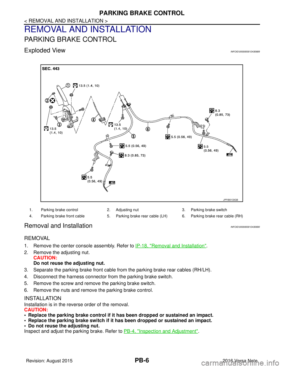
Exploded ViewINFOID:0000000012430689
Removal and InstallationINFOID:0000000012430690
REMOVAL
1. Remove the center console assembly. Refer to IP-18, "Removal and Installation".
2. Remove the adjusting nut. CAUTION:
Do not reuse the adjusting nut.
3. Separate the parking brake front cable fr om the parking brake rear cables (RH/LH).
4. Disconnect the harness connector fr om the parking brake switch.
5. Remove the screw and remove the parking brake switch.
6. Remove the nuts and remove the parking brake control.
INSTALLATION
Installation is in the reverse order of the removal.
CAUTION:
• Replace the parking brake control if it h as been dropped or sustained an impact.
• Replace the parking brake switch if it h as been dropped or sustained an impact.
• Do not reuse the adjusting nut.
Inspect and adjust the parking brake. Refer to PB-4, "
Inspection and Adjustment".
1. Parking brake control2. Adjusting nut3. Parking brake switch
4. Parking brake front cable 5. Parking brake rear cable (LH) 6. Parking brake rear cable (RH)
JPFIB0133GB
Revision: August 2015 2016 Versa Note
cardiagn.com
Page 2500 of 3641
PARKING BRAKE CABLEPB-7
< REMOVAL AND INSTALLATION >
C
DE
G H
I
J
K L
M A
B
PB
N
O P
PARKING BRAKE CABLE
Removal and InstallationINFOID:0000000012430691
REMOVAL
1. Remove the center console assembly. Refer to IP-18, "Removal and Installation".
2. Remove the adjusting nut. Refer to PB-6, "
Exploded View".
3. Separate the parking brake front cable from parking brake rear cables (RH/LH). Refer to PB-6, "
Exploded
View".
CAUTION:
To prevent damage to the parts, do not bend the parking brake cables.
4. Remove the parking brake front cable.
INSTALLATION
Installation is in the reverse order of removal.
CAUTION:
Do not reuse the adjusting nut.
• Inspect and adjust the parking brake. Refer to PB-4, "
Inspection and Adjustment".
Revision: August 2015 2016 Versa Note
cardiagn.com
Page 2501 of 3641
PB-8
< REMOVAL AND INSTALLATION >
PARKING BRAKE REAR CABLE
PARKING BRAKE REAR CABLE
Removal and InstallationINFOID:0000000012430692
REMOVAL
1. Remove the center console assembly. Refer to IP-18, "Removal and Installation".
2. Loosen the adjusting nut. Refer to PB-6, "
Exploded View".
NOTE:
It is not necessary to remove the parking brake front cable.
3. Separate the parking brake rear cables (RH/LH ) from the parking brake front cable. Refer to PB-6,
"Exploded View".
4. Remove the rear wheels and tires using power tool. Refer to WT-48, "
Exploded View".
5. Remove rear wheel sensors. Refer to BRC-143, "
REAR SENSOR ROTOR : Removal and Installation".
6. Remove the rear drum brake components. Refer to BR-41, "
Removal and Installation".
CAUTION:
Do not separate the brake tube from the wheel cylinders.
7. Remove the center muffler. Refer to EX-5, "
Exploded View".
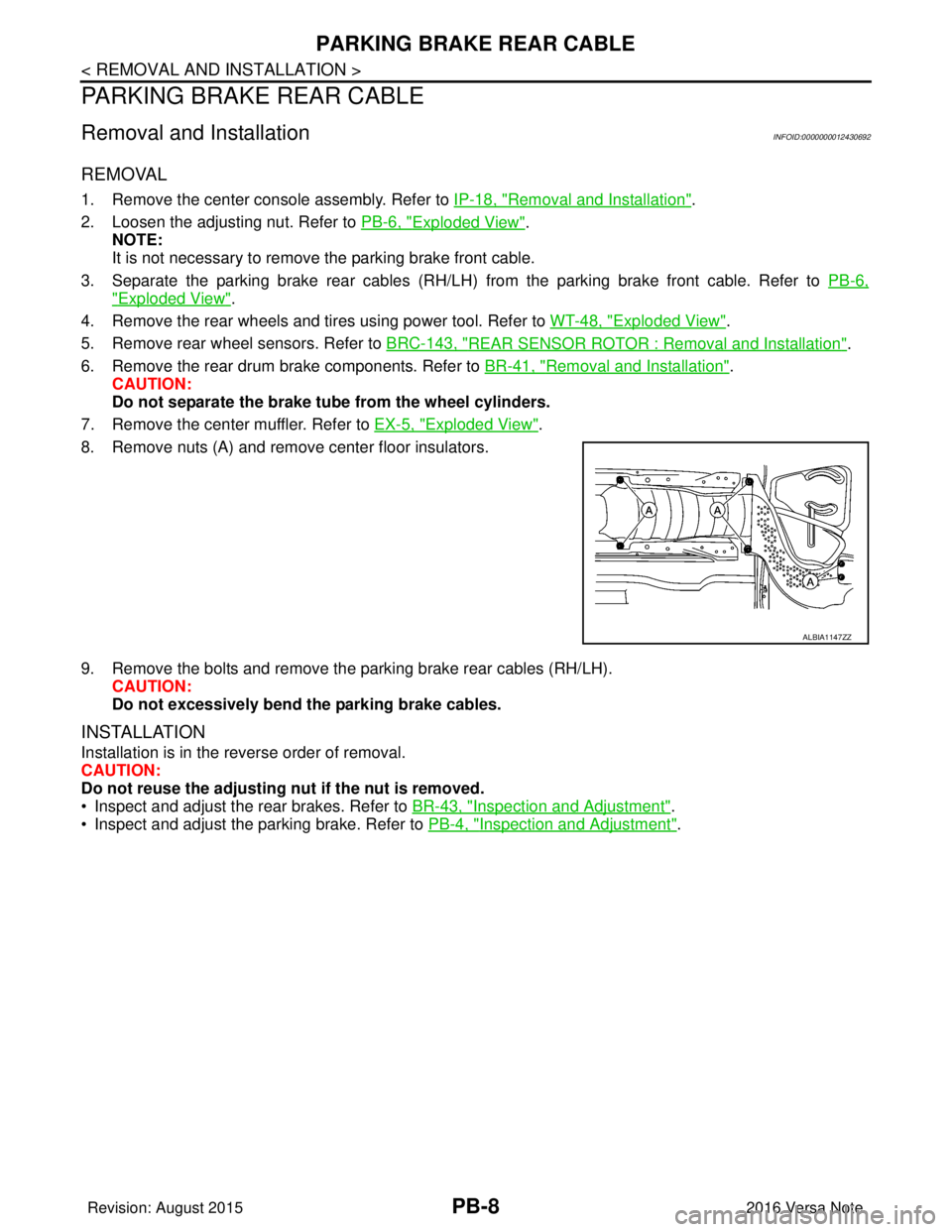
8. Remove nuts (A) and remove center floor insulators.
9. Remove the bolts and remove the parking brake rear cables (RH/LH). CAUTION:
Do not excessively bend the parking brake cables.
INSTALLATION
Installation is in the reverse order of removal.
CAUTION:
Do not reuse the adjusting nut if the nut is removed.
• Inspect and adjust the rear brakes. Refer to BR-43, "
Inspection and Adjustment".
• Inspect and adjust the parking brake. Refer to PB-4, "
Inspection and Adjustment".
ALBIA1147ZZ
Revision: August 2015 2016 Versa Note
cardiagn.com
Page 2502 of 3641
PARKING BRAKE SWITCHPB-9
< REMOVAL AND INSTALLATION >
C
DE
G H
I
J
K L
M A
B
PB
N
O P
PARKING BRAKE SWITCH
Removal and InstallationINFOID:0000000012430693
REMOVAL
1. Remove the center console assembly. Refer to PB-6, "Exploded View".
2. Disconnect the harness connector from the parking brake switch. Refer to PB-6, "
Exploded View".
3. Remove the screw and remove the parking brake switch. Refer to PB-6, "
Exploded View".
INSTALLATION
Installation is in the reverse order of removal.
CAUTION:
Replace the parking brake switch if it has been dropped or sustained an impact.
Adjust the parking brake cable if necessary. Refer to PB-4, "
Inspection and Adjustment".
Revision: August 2015 2016 Versa Note
cardiagn.com
Page 2631 of 3641

PG-44
< WIRING DIAGRAM >
HARNESS
C2 M6 W/4 : Dongle unitB1 M61 — : Body ground
B2 M7 W/16 : Door mirror remote control switch C1 M62 W/2 : Front blower motor
D1 M8 G/20 : Joint connector–M02 C3 M64 W/8 : Steering angle sensor
A3 M9 W/12 : To D1 E3 M65 W/4 : Front air control
D3 M10 L/20 : Joint connector–M01 D5 M66 B/3 : Console power socket
B4 M11 W/2 : To B28 A4 M69 SMJ : To E7
F3 M12 W/16 : To B29 E2 M70 W/20 : AV control unit
F3 M13 W/24 : To B30 D3 M71 W/24 : AV control unit
B3 M14 BR/6 : Rear window defogger relay F2 M75 Y/4 : To D101
B4 M15 W/16 : To B23 D2 M76 GR/5 : AV control unit
A4 M16 W/24 : To B24 E1 M77 Y/4 : Front passenger air bag module
D5 M17 B/1 : Parking brake switch A4 M78 B/2 :To E11
A2 M18 W/40 : BCM (Body contro
l module) (Without
Intelligent Key system) F1 M79 — : Body ground
A1 M19 W/15 : BCM (Body contro
l module) (Without
Intelligent Key system) A 3 M 8 0 Y / 4 : T o D 3
A2 M20 B/15 : BCM (Body contro
l module) (Without
Intelligent Key system) F2 M81 W/12 : To D115
C2 M21 W/4 : NATS antenna amp. C1 M82 W/40 : Combination meter (With type A)
B3 M22 W/16 : Data link connector D5 M83 B/3 : G sensor
E 4 M 2 3 W / 4 : Remote keyless entry receiver (Without
Intelligent Key system) E2 M84 — : Body ground
C1 M24 W/40 : Combination meter (With type B) E2 M85 — : Body ground
C4 M25 W/8 : Push–button ignition swtich F5 M89 L/2 : Inside key antenna (Console)
C3 M26 W/6 : Ignition switch E1 M90 B/4: Remote keyless entry receiver (With
Intelligent Key system without tire pressure
monitoring system)
C2 M27 BR/2 : Key switch F2 M92 W/12 : To D116
C3 M28 W/16 : Combination switch A3 M93 W/24 : To D16
E 3 M 2 9 W / 2 4 : T o B 1 F 1 M 9 4 W / 4: Remote keyless entry receiver (With
Intelligent Key system with tire pressure
monitoring system)
C4 M30 GR/8 : Combination switch (Spiral cable) D3 M95 L/2 : Inside key antenna (Instrument center)
C3 M31 Y/6 : Combination switch (Spiral cable) A2 M97 B/40 : BCM (Body contro
l module) (With
Intelligent Key system)
E5 M32 W/16 : To M201 A2 M98 W/40: BCM (Body contro
l module) (With
Intelligent Key system)
E3 M33 B/15 : Front air control A2 M99 W/15: BCM (Body contro
l module) (With
Intelligent Key system)
B3 M34 GR/6 : VDC off switch A2 M100 B / 1 5: BCM (Body contro
l module) (With
Intelligent Key system)
D4 M35 Y/28 : Air bag diagnosis sensor unit D2 M101 W/16 : Audio unit (With base audio system)
D1 M36 BR/2 : Front passenger air bag off indicator A3 M103 W/12 : Accessory prewire LH
E4 M38 W/8 : CVT shift selector E2 M104 W/12 : Accessory prewire RH
B3 M39 L/4 : Accessory relay–2 C2 M151 BR/4 : Front blower motor resistor
E2 M40 W/32 : Audio unit (With display audio system) Console sub harness
B3 M41 B/5 : Back door lock actuator relay E5 M201 W / 1 6 : T o M 3 2
C3 M42 BR/4 : Thermo control amp. E4 M202 B/3 : Console power socket
E2 M43 W/20 : Audio unit (With base audio system) C4 M203 BR/6 : Heated seat swtich RH
Revision: August 2015 2016 Versa Note
cardiagn.com
Page 2823 of 3641

SE-10
< SYMPTOM DIAGNOSIS >
SQUEAK AND RATTLE TROUBLE DIAGNOSES
INSTRUMENT PANEL
Most incidents are caused by contact and movement between:
1. Cluster lid A and the instrument panel
2. Acrylic lens and combination meter housing
3. Instrument panel to front pillar finisher
4. Instrument panel to windshield
5. Instrument panel pins
6. Wiring harnesses behind the combination meter
7. A/C defroster duct and duct joint
These incidents can usually be located by tapping or moving the components to duplicate the noise or by
pressing on the components while driving to stop the noise. Most of these incidents can be repaired by apply-
ing felt cloth tape or silicone spray (in hard to reach areas). Urethane pads can be used to insulate wiring har-
ness.
CAUTION:
Do not use silicone spray to isolate a squeak or rattle. If you saturate the ar ea with silicone, you will
not be able to recheck the repair.
CENTER CONSOLE
Components to pay attention to include:
1. Shift selector assembly cover to finisher
2. A/C control unit and cluster lid C
3. Wiring harnesses behind audio and A/C control unit
The instrument panel repair and isolation pr ocedures also apply to the center console.
DOORS
Pay attention to the:
1. Finisher and inner panel making a slapping noise
2. Inside handle escutcheon to door finisher
3. Wiring harnesses tapping
4. Door striker out of alignment causing a popping noise on starts and stops
Tapping or moving the components or pressing on them wh ile driving to duplicate the conditions can isolate
many of these incidents. You can usually insulate the areas with felt cloth tape or insulator foam blocks from
the NISSAN Squeak and Rattle Kit (J-50397) to repair the noise.
TRUNK
Trunk noises are often caused by a loose jack or loose items put into the trunk by the owner.
In addition look for:
1. Trunk lid bumpers out of adjustment
2. Trunk lid striker out of adjustment
3. The trunk lid torsion bars knocking together
4. A loose license plate or bracket
Most of these incidents can be repaired by adjusting, se curing or insulating the item(s) or component(s) caus-
ing the noise.
SUNROOF/HEADLINING
Noises in the sunroof/headlining area c an often be traced to one of the following:
1. Sunroof lid, rail, linkage or seals making a rattle or light knocking noise
2. Sun visor shaft shaking in the holder
3. Front or rear windshield touching headlining and squeaking
Again, pressing on the components to stop the noise while duplicating the conditions can isolate most of these
incidents. Repairs usually consist of insulating with felt cloth tape.
OVERHEAD CONSOLE (FRONT AND REAR)
Overhead console noises are often caused by the c onsole panel clips not being engaged correctly. Most of
these incidents are repaired by pushing up on the c onsole at the clip locations until the clips engage.
In addition look for:
Revision: August 2015 2016 Versa Note
cardiagn.com
Page 2842 of 3641
FRONT HEATED SEAT SWITCHSE-29
< REMOVAL AND INSTALLATION >
C
DE
F
G H
I
K L
M A
B
SE
N
O P
FRONT HEATED SEAT SWITCH
Removal and InstallationINFOID:0000000012432047
REMOVAL
1. Remove the center console assembly. Refer to IP-18, "Removal and Installation".
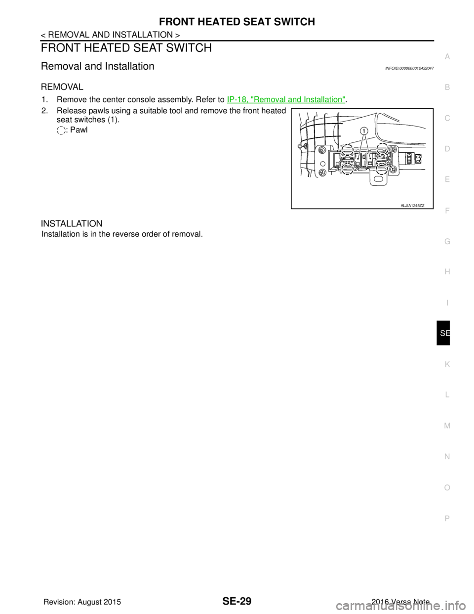
2. Release pawls using a suitable tool and remove the front heated seat switches (1).
: Pawl
INSTALLATION
Installation is in the reverse order of removal.
ALJIA1245ZZ
Revision: August 2015 2016 Versa Note
cardiagn.com
Page 2867 of 3641
![NISSAN NOTE 2016 Service Repair Manual SEC-10
< SYSTEM DESCRIPTION >[WITH INTELLIGENT KEY SYSTEM]
COMPONENT PARTS
When power supply position is turned ON, BCM starts
communication with ECM and performs the ID verifica-
tion between BCM an NISSAN NOTE 2016 Service Repair Manual SEC-10
< SYSTEM DESCRIPTION >[WITH INTELLIGENT KEY SYSTEM]
COMPONENT PARTS
When power supply position is turned ON, BCM starts
communication with ECM and performs the ID verifica-
tion between BCM an](/manual-img/5/57363/w960_57363-2866.png)
SEC-10
< SYSTEM DESCRIPTION >[WITH INTELLIGENT KEY SYSTEM]
COMPONENT PARTS
When power supply position is turned ON, BCM starts
communication with ECM and performs the ID verifica-
tion between BCM and ECM.
If the verification result is OK, the engine can start. If the verification result is invalid, the engine can not start.
IPDM E/RINFOID:0000000012430328
IPDM E/R has the starter relay and starter control relay inside. Starter relay and starter control relay are used
for the engine starting function. IPDM E/R controls these relays while communicating with BCM.
NATS Antenna Amp.INFOID:0000000012430329
The ID verification is performed between BCM and transponder in Intelligent Key via NATS antenna amp.
when Intelligent Key backside is contacted to push-button igni tion switch in case that Intelligent Key battery is
discharged. If the ID verification result is OK, the operation of starting engine is available.
Combination MeterINFOID:0000000012430330
Combination meter transmits the vehicle speed signal to BCM via CAN communication.
BCM also receives the vehicle speed signal from ABS ac tuator and electric unit (control unit) via CAN commu-
nication. BCM compares both signals to detect the vehicle speed.
Door SwitchINFOID:0000000012430331
Door switch detects door open/close conditi on and then transmits ON/OFF signal to BCM.
Outside Key AntennaINFOID:0000000012430332
Outside key antenna detects whether Intelligent Key is outside the vehicle and transmits the signal to BCM.
Three outside key antennas are installed in the front outside handle LH, front outside handle RH and rear
bumper.
Inside Key AntennaINFOID:0000000012430333
Inside key antenna detects whether Intelligent Key is inside the vehicle and transmits the signal to BCM.
Three inside key antennas are installed in the instrument center, console and trunk room.
Remote Keyless Entry ReceiverINFOID:0000000012430334
Remote keyless entry receiver receives each button oper ation signal and electronic key ID signal from Intelli-
gent Key and then transmits the signal to BCM.
Intelligent KeyINFOID:0000000012430335
Each Intelligent Key has an individual electronic ID and transmits the ID signal by request from BCM.
Carrying the Intelligent Key whose ID is registered in BC M, the driver can perform, remote start, door lock/
unlock operation, remote liftgate, panic alarm and push-button ignition switch operation.
Push-button Ignition SwitchINFOID:0000000012430336
Push-button ignition switch detects that push-button is pressed and then transmits the signal to BCM. BCM
changes the power supply position with the operation of push-button ignition switch. BCM maintains the power
supply position status while push-button is not operated.
Security Indicator LampINFOID:0000000012430337
Security indicator lamp is located on combination meter.
Security indicator lamp blinks when power supply positi on is any position other than ON to warn that NISSAN
VEHICLE IMMOBILIZER SYSTEM-NATS (NATS) is on board.
Starter RelayINFOID:0000000012430338
Engine starting system functions by controlling both starter relay and starter control relay.
Starter relay is controlled by BCM, and starter contro l relay is controlled by IPDM E/R on request from BCM.
IPDM E/R transmits starter relay and starter control relay status signal to BCM via CAN communication.
Revision: August 2015 2016 Versa Note
cardiagn.com