2016 NISSAN NOTE brake light
[x] Cancel search: brake lightPage 1661 of 3641
SYSTEMEXL-9
< SYSTEM DESCRIPTION >
C
DE
F
G H
I
J
K
M A
B
EXL
N
O P
Under this condition, the headlamps remain illuminated for 45 seconds unless the lighting switch position is
changed. If the lighting switch position is changed, then the headlamps are turned off.
This setting can be changed by CONSULT. Refer to BCS-20, "
HEADLAMP : CONSULT Function (BCM -
HEAD LAMP)" (with Intelligent Key system) or BCS-93, "HEADLAMP : CONSULT Function (BCM - HEAD
LAMP)" (without Intelligent Key system).
DAYTIME RUNNING LIGHT SYSTEM
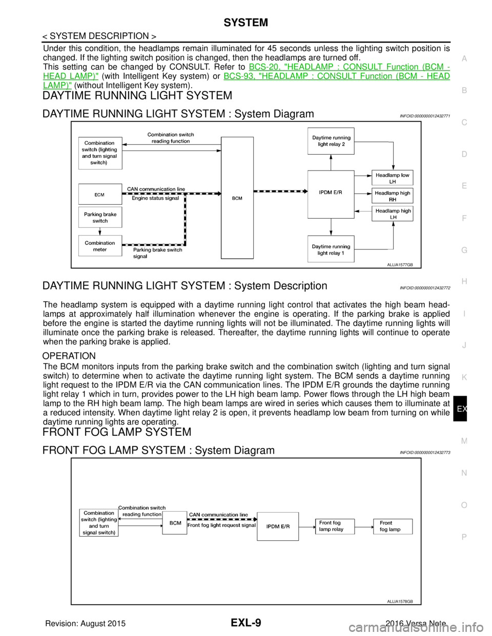
DAYTIME RUNNING LIGHT SYSTEM : System DiagramINFOID:0000000012432771
DAYTIME RUNNING LIGHT SYST EM : System DescriptionINFOID:0000000012432772
The headlamp system is equipped with a daytime running light control that activates the high beam head-
lamps at approximately half illumination whenever the e ngine is operating. If the parking brake is applied
before the engine is started the daytime running lights will not be illuminated. The daytime running lights will
illuminate once the parking brake is released. Thereaf ter, the daytime running lights will continue to operate
when the parking brake is applied.
OPERATION
The BCM monitors inputs from the parking brake swit ch and the combination switch (lighting and turn signal
switch) to determine when to activate the daytime running light system. The BCM sends a daytime running
light request to the IPDM E/R via the CAN communication lines. The IPDM E/R grounds the daytime running
light relay 1 which in turn, provides power to the LH high beam lamp. Power flows through the LH high beam
lamp to the RH high beam lamp. The high beam lamps are wired in series which causes them to illuminate at
a reduced intensity. When daytime light relay 2 is open, it prevents headlamp low beam from turning on while
daytime running lights are operating.
FRONT FOG LAMP SYSTEM
FRONT FOG LAMP SYSTEM : System DiagramINFOID:0000000012432773
ALLIA1577GB
ALLIA1578GB
Revision: August 2015 2016 Versa Note
cardiagn.com
Page 1743 of 3641
EXTERIOR LIGHTING SYSTEM SYMPTOMSEXL-91
< SYMPTOM DIAGNOSIS >
C
DE
F
G H
I
J
K
M A
B
EXL
N
O P
SYMPTOM DIAGNOSIS
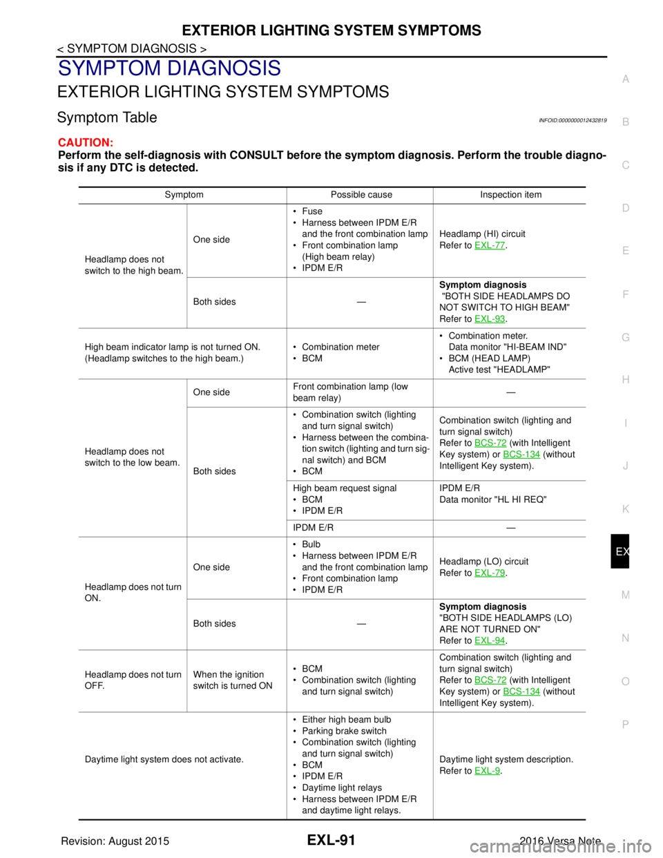
EXTERIOR LIGHTING SYSTEM SYMPTOMS
Symptom TableINFOID:0000000012432819
CAUTION:
Perform the self-diagnosis with CONSULT before th e symptom diagnosis. Perform the trouble diagno-
sis if any DTC is detected.
Symptom Possible causeInspection item
Headlamp does not
switch to the high beam. One side
•Fuse
• Harness between IPDM E/R
and the front combination lamp
• Front combination lamp
(High beam relay)
• IPDM E/R Headlamp (HI) circuit
Refer to EXL-77
.
Both sides — Symptom diagnosis
"BOTH SIDE HEADLAMPS DO
NOT SWITCH TO HIGH BEAM"
Refer to EXL-93
.
High beam indicator lamp is not turned ON.
(Headlamp switches to the high beam.) • Combination meter
•BCM• Combination meter.
Data monitor "HI-BEAM IND"
• BCM (HEAD LAMP)
Active test "HEADLAMP"
Headlamp does not
switch to the low beam. One side
Front combination lamp (low
beam relay) —
Both sides • Combination switch (lighting
and turn signal switch)
• Harness between the combina- tion switch (lighting and turn sig-
nal switch) and BCM
•BCM Combination switch (lighting and
turn signal switch)
Refer to BCS-72
(with Intelligent
Key system) or BCS-134
(without
Intelligent Key system).
High beam request signal
•BCM
• IPDM E/R IPDM E/R
Data monitor "HL HI REQ"
IPDM E/R —
Headlamp does not turn
ON. One side
•Bulb
• Harness between IPDM E/R
and the front combination lamp
• Front combination lamp
• IPDM E/R Headlamp (LO) circuit
Refer to EXL-79
.
Both sides — Symptom diagnosis
"BOTH SIDE HEADLAMPS (LO)
ARE NOT TURNED ON"
Refer to EXL-94
.
Headlamp does not turn
OFF. When the ignition
switch is turned ON•BCM
• Combination switch (lighting
and turn signal switch) Combination switch (lighting and
turn signal switch)
Refer to BCS-72
(with Intelligent
Key system) or BCS-134
(without
Intelligent Key system).
Daytime light system does not activate. • Either high beam bulb
• Parking brake switch
• Combination switch (lighting
and turn signal switch)
•BCM
• IPDM E/R
• Daytime light relays
• Harness between IPDM E/R
and daytime light relays. Daytime light system description.
Refer to EXL-9
.
Revision: August 2015
2016 Versa Note
cardiagn.com
Page 1836 of 3641
FRONT DRIVE SHAFTFAX-19
< REMOVAL AND INSTALLATION >
CEF
G H
I
J
K L
M A
B
FA X
N
O P
FRONT DRIVE SHAFT
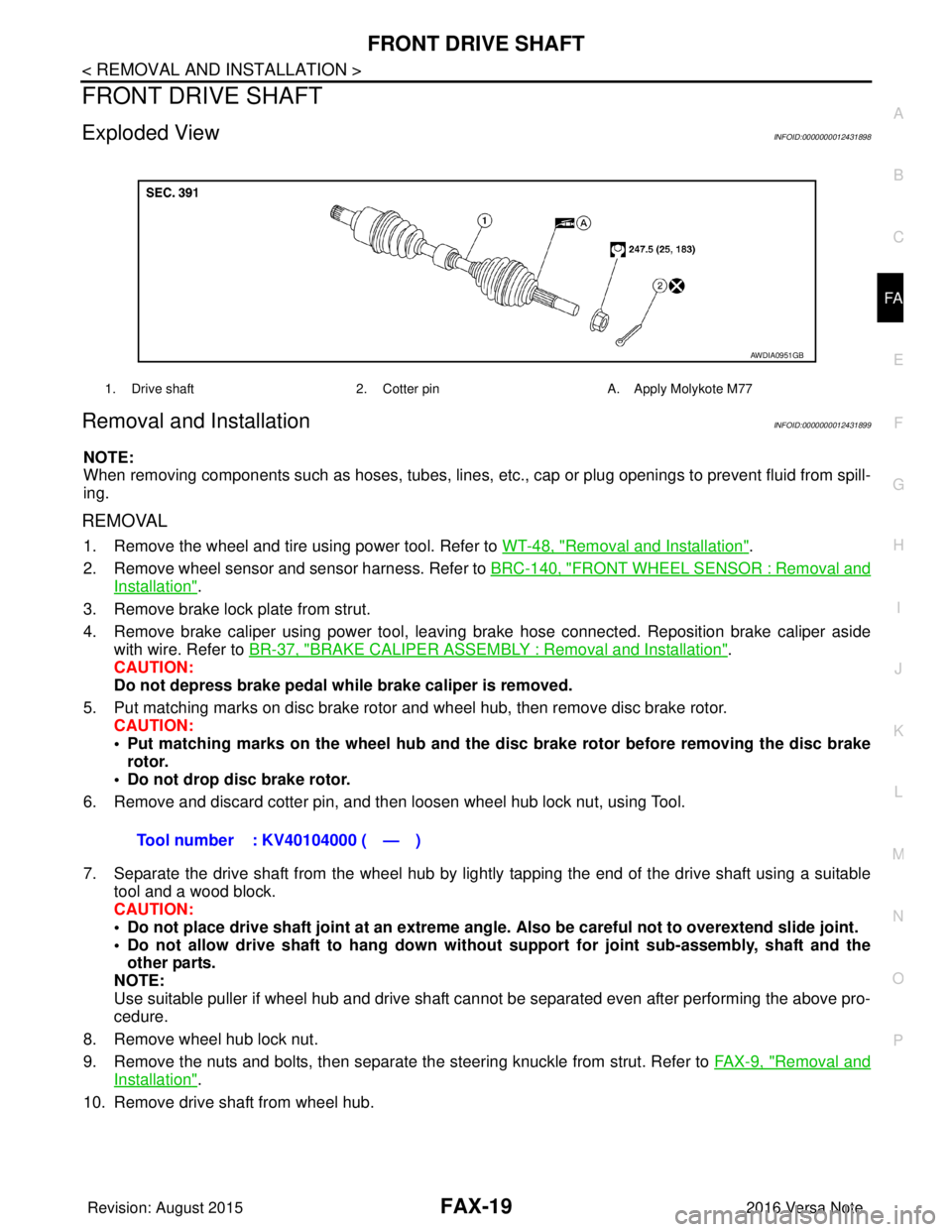
Exploded ViewINFOID:0000000012431898
Removal and InstallationINFOID:0000000012431899
NOTE:
When removing components such as hoses, tubes, lines, etc. , cap or plug openings to prevent fluid from spill-
ing.
REMOVAL
1. Remove the wheel and tire using power tool. Refer to WT-48, "Removal and Installation".
2. Remove wheel sensor and sensor harness. Refer to BRC-140, "
FRONT WHEEL SENSOR : Removal and
Installation".
3. Remove brake lock plate from strut.
4. Remove brake caliper using power tool, leaving brake hose connected. Reposition brake caliper aside with wire. Refer to BR-37, "
BRAKE CALIPER ASSEMBLY : Removal and Installation".
CAUTION:
Do not depress brake pedal while brake caliper is removed.
5. Put matching marks on disc brake rotor and wheel hub, then remove disc brake rotor. CAUTION:
• Put matching marks on the wheel hub and the disc brake rotor before removing the disc brake
rotor.
• Do not drop disc brake rotor.
6. Remove and discard cotter pin, and then loosen wheel hub lock nut, using Tool.
7. Separate the drive shaft from the wheel hub by lightly tapping the end of the drive shaft using a suitable tool and a wood block.
CAUTION:
• Do not place drive shaft joint at an extreme angle. Also be careful not to overextend slide joint.
• Do not allow drive shaft to ha ng down without support for joint sub-assembly, shaft and the
other parts.
NOTE:
Use suitable puller if wheel hub and drive shaft cannot be separated even after performing the above pro-
cedure.
8. Remove wheel hub lock nut.
9. Remove the nuts and bolts, then separate the steering knuckle from strut. Refer to FA X - 9 , "
Removal and
Installation".
10. Remove drive shaft from wheel hub.
1. Drive shaft 2. Cotter pinA. Apply Molykote M77
AWDIA0951GB
Tool number : KV40104000 ( — )
Revision: August 2015 2016 Versa Note
cardiagn.com
Page 1904 of 3641

GI-16
< HOW TO USE THIS MANUAL >
ABBREVIATIONS
I
K
L
M
N
HOCHeated oxidation catalyst
HPCM Hybrid power train control module
ABBREVIATION DESCRIPTION
I/M Inspection and maintenance
IA Intake air
IAC Idle air control
IAT Intake air temperature
IBA Intelligent brake assist
IC Ignition control
ICC Intelligent cruise control
ICM Ignition control module
IPDM E/R Intelligent power distribution module engine room ISC Idle speed control
ISS Input shaft speed
ITS Information technology suite
ABBREVIATION DESCRIPTION
KS Knock sensor
ABBREVIATION DESCRIPTION
LBC Li-ion battery controller
LCD Liquid crystal display
LCU Local control unit
LDP Lane departure prevention
LDW Lane departure warning
LED Light emitting diode
LH Left-hand
LHD Left-hand drive
LIN Local interconnect network
ABBREVIATION DESCRIPTION
M/T Manual transaxle/transmission
MAF Mass airflow
MAP Manifold absolute pressure
MDU Multi display unit
MI Malfunction indicator
MIL Malfunction indicator lamp
MOD Moving object detection
ABBREVIATION DESCRIPTION
NOX Nitrogen oxides
ABBREVIATION
DESCRIPTION
Revision: August 2015 2016 Versa Note
cardiagn.com
Page 2087 of 3641
CENTER CONSOLE ASSEMBLYIP-19
< REMOVAL AND INSTALLATION >
C
DE
F
G H
I
K L
M A
B
IP
N
O P
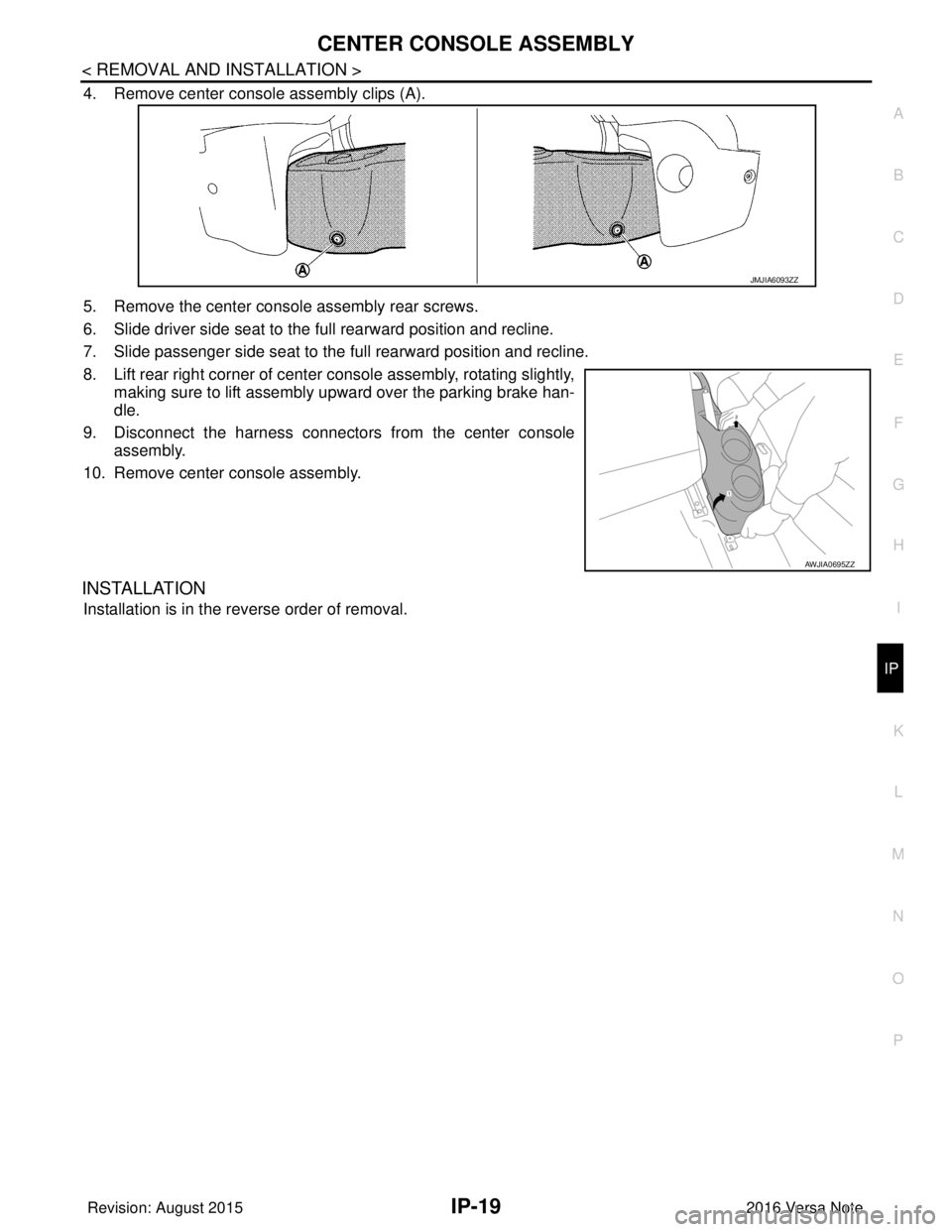
4. Remove center console assembly clips (A).
5. Remove the center console assembly rear screws.
6. Slide driver side seat to the full rearward position and recline.
7. Slide passenger side seat to the full rearward position and recline.
8. Lift rear right corner of center console assembly, rotating slightly, making sure to lift assembly upward over the parking brake han-
dle.
9. Disconnect the harness connectors from the center console assembly.
10. Remove center console assembly.
INSTALLATION
Installation is in the reverse order of removal.
JMJIA6093ZZ
AWJIA0695ZZ
Revision: August 2015 2016 Versa Note
cardiagn.com
Page 2326 of 3641
RECOMMENDED FLUIDS AND LUBRICANTSMA-11
< PERIODIC MAINTENANCE >
C
DE
F
G H
I
J
K L
M B
MA
N
O A
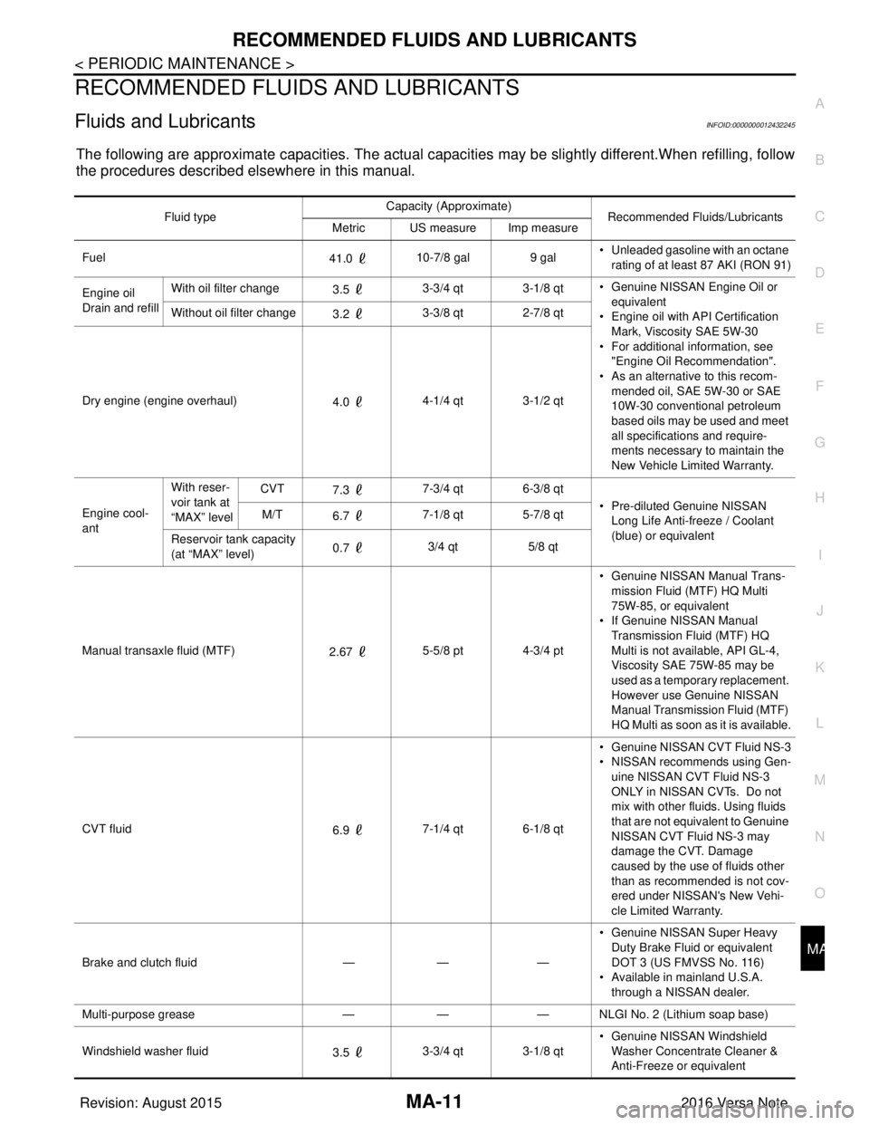
RECOMMENDED FLUIDS AND LUBRICANTS
Fluids and LubricantsINFOID:0000000012432245
The following are approximate capacities. The actual capa
cities may be slightly different.When refilling, follow
the procedures described elsewhere in this manual.
Fluid type Capacity (Approximate)
Recommended Fluids/Lubricants
Metric US measure Imp measure
Fuel 41.0 10-7/8 gal
9 gal• Unleaded gasoline with an octane
rating of at least 87 AKI (RON 91)
Engine oil
Drain and refill With oil filter change
3.5 3-3/4 qt 3-1/8 qt
• Genuine NISSAN Engine Oil or
equivalent
• Engine oil with API Certification
Mark, Viscosity SAE 5W-30
• For additional information, see "Engine Oil Recommendation".
• As an alternative to this recom-
mended oil, SAE 5W-30 or SAE
10W-30 conventional petroleum
based oils may be used and meet
all specifications and require-
ments necessary to maintain the
New Vehicle Limited Warranty.
Without oil filter change
3.2 3-3/8 qt 2-7/8 qt
Dry engine (engine overhaul) 4.0 4-1/4 qt 3-1/2 qt
Engine cool-
ant With reser-
voir tank at
“MAX” level
CVT
7.3 7-3/4 qt 6-3/8 qt
• Pre-diluted Genuine NISSAN Long Life Anti-freeze / Coolant
(blue) or equivalent
M/T
6.7 7-1/8 qt 5-7/8 qt
Reservoir tank capacity
(at “MAX” level) 0.7
3/4 qt
5/8 qt
Manual transaxle fluid (MTF) 2.67 5-5/8 pt 4-3/4 pt • Genuine NISSAN
Manual Trans-
mission Fluid (MTF) HQ Multi
75W-85, or equivalent
• If Genuine NISSAN Manual
Transmission Fluid (MTF) HQ
Multi is not available, API GL-4,
Viscosity SAE 75W-85 may be
used as a temporary replacement.
However use Genuine NISSAN
Manual Transmission Fluid (MTF)
HQ Multi as soon as it is available.
CVT fluid 6.9 7-1/4 qt 6-1/8 qt • Genuine NISSAN CVT Fluid NS-3
• NISSAN recommends using Gen-
uine NISSAN CVT Fluid NS-3
ONLY in NISSAN CVTs. Do not
mix with other fluids. Using fluids
that are not equivalent to Genuine
NISSAN CVT Fluid NS-3 may
damage the CVT. Damage
caused by the use of fluids other
than as recommended is not cov-
ered under NISSAN's New Vehi-
cle Limited Warranty.
Brake and clutch fluid —— —• Genuine NISSAN Super Heavy
Duty Brake Fluid or equivalent
DOT 3 (US FMVSS No. 116)
• Available in mainland U.S.A.
through a NISSAN dealer.
Multi-purpose grease —— — NLGI No. 2 (Lithium soap base)
Windshield washer fluid 3.5 3-3/4 qt 3-1/8 qt • Genuine NISSAN Windshield
Washer Concentrate Cleaner &
Anti-Freeze or equivalent
Revision: August 2015 2016 Versa Note
cardiagn.com
Page 2370 of 3641
![NISSAN NOTE 2016 Service Repair Manual MWI-12
< SYSTEM DESCRIPTION >[TYPE A]
SYSTEM
SPEEDOMETER
SPEEDOMETER : System DescriptionINFOID:0000000012432545
SYSTEM DIAGRAM
DESCRIPTION
The ABS actuator and electric unit (control unit) receives e NISSAN NOTE 2016 Service Repair Manual MWI-12
< SYSTEM DESCRIPTION >[TYPE A]
SYSTEM
SPEEDOMETER
SPEEDOMETER : System DescriptionINFOID:0000000012432545
SYSTEM DIAGRAM
DESCRIPTION
The ABS actuator and electric unit (control unit) receives e](/manual-img/5/57363/w960_57363-2369.png)
MWI-12
< SYSTEM DESCRIPTION >[TYPE A]
SYSTEM
SPEEDOMETER
SPEEDOMETER : System DescriptionINFOID:0000000012432545
SYSTEM DIAGRAM
DESCRIPTION
The ABS actuator and electric unit (control unit) receives each wheel speed sensor signal and provides a vehi-
cle speed signal to the combination meter via CAN communication.
TACHOMETER
TACHOMETER : System DescriptionINFOID:0000000012432546
SYSTEM DIAGRAM
DESCRIPTION
The crank position sensor sends a crankshaft positi
on signal to the ECM. The ECM provides an engine speed
signal to the combination meter via CAN communication lines. The tachometer indicates engine speed in rev-
olutions per minute (rpm).
SHIFT POSITION INDICATOR
Warning lamp/indicator lamp ABS warning lamp
The lamp turns ON by suspending communication.
Slip indicator lamp
Malfunction indicator lamp (MIL)
VDC OFF indicator lamp
EPS warning lamp
Brake warning lamp
High beam indicator lamp
The lamp turns OFF by suspending communication.
Turn signal indicator lamp
Door warning lamp
Light indicator lamp
Engine oil pressure warning lamp
O/D OFF indicator lamp
Function
Specifications
AWNIA2379GB
JSNIA2462GB
Revision: August 2015 2016 Versa Note
cardiagn.com
Page 2376 of 3641
![NISSAN NOTE 2016 Service Repair Manual MWI-18
< SYSTEM DESCRIPTION >[TYPE A]
DIAGNOSIS SYSTEM (COMBINATION METER)
NOTE:
• If any of the meters or gauges is not activated, replace combination meter.
• The figure is reference.
CONSULT Fu NISSAN NOTE 2016 Service Repair Manual MWI-18
< SYSTEM DESCRIPTION >[TYPE A]
DIAGNOSIS SYSTEM (COMBINATION METER)
NOTE:
• If any of the meters or gauges is not activated, replace combination meter.
• The figure is reference.
CONSULT Fu](/manual-img/5/57363/w960_57363-2375.png)
MWI-18
< SYSTEM DESCRIPTION >[TYPE A]
DIAGNOSIS SYSTEM (COMBINATION METER)
NOTE:
• If any of the meters or gauges is not activated, replace combination meter.
• The figure is reference.
CONSULT Function (METER/M&A)INFOID:0000000012432553
APPLICATION ITEMS
CONSULT can display each diagnostic item
using the diagnostic test modes shown.
SELF DIAG RESULT
Refer to MWI-24, "DTC Index".
DATA MONITOR
Display Item List
X: Applicable
METER/M&A Diagnosis mode Description
Self Diagnostic Result The combination meter self-diagnosis results.
Data Monitor Displays combination meter input/output data in real time.
Work support Supports combination meter diagnosis.
ECU Identification The combination meter part number is displayed.
Warning History Lighting history of the warning lamp and indicator lamp can be checked.
Display item [Unit]MAIN
SIGNALS Description
SPEED METER
[mph] or [km/h] X Displays the value of vehicle speed signal.
SPEED OUTPUT
[mph] or [km/h] X Displays the value of vehicle speed signal, which is transmitted to each unit with CAN communication.
ODO OUTPUT
[Mi] or [km] Displays odometer signal value transmitted to other units via CAN communication.
TACHO METER
[rpm] X Displays the value of engine speed signal, which is input from ECM.
FUEL METER
[L] X Displays the fuel level.
W TEMP METER
[ ° F] or [ °C] X Displays the value of engine coolant temperature signal, which is input from ECM.
ABS W/L
[ON/OFF] Displays [ON/OFF] conditio
n of ABS warning indicator
VDC/TCS IND
[ON/OFF] Displays [ON/OFF] condition
of VDC OFF indicator lamp.
SLIP IND
[ON/OFF] Displays [ON/OFF] condition of SLIP indicator lamp.
BRAKE W/L
[ON/OFF] Displays [ON/OFF] condition of brake warning indicator.
DOOR W/L
[ON/OFF] Displays [ON/OFF] condition of door warning indicator.
HI-BEAM IND
[ON/OFF] Displays [ON/OFF] condition of high beam indicator.
TURN IND
[ON/OFF] Displays [ON/OFF] condition of turn indicator.
LIGHT IND
[ON/OFF] Displays [ON/OFF] condition of light indicator.
OIL W/L
[ON/OFF] Displays [ON/OFF] condition of engine oil pressure warning indicator.
Revision: August 2015
2016 Versa Note
cardiagn.com