2016 NISSAN NOTE brake light
[x] Cancel search: brake lightPage 2497 of 3641

PB-4
< PERIODIC MAINTENANCE >
PARKING BRAKE SYSTEM
PERIODIC MAINTENANCE
PARKING BRAKE SYSTEM
Inspection and AdjustmentINFOID:0000000012430688
INSPECTION
Parking Brake Control Stroke
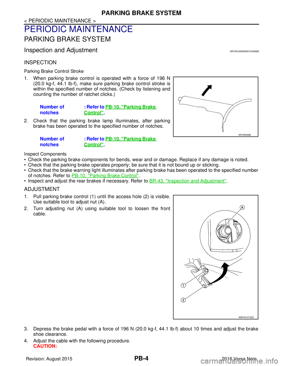
1. When parking brake control is operated with a force of 196 N(20.0 kg-f, 44.1 lb-f), make sure parking brake control stroke is
within the specified number of notches. (Check by listening and
counting the number of ratchet clicks.)
2. Check that the parking brake lamp illuminates, after parking brake has been operated to the specified number of notches.
Inspect Components
• Check the parking brake components for bends, wear and or damage. Replace if any damage is noted.
• Check that the parking brake operates properly ; be sure that it is not bound up or sticking.
• Check that the brake warning light illuminates afte r parking brake has been operated to the specified number
of notches. Refer to PB-10, "
Parking Brake Control".
• Inspect and adjust the rear brakes if necessary. Refer to BR-43, "
Inspection and Adjustment".
ADJUSTMENT
1. Pull parking brake control (1) until the access hole (2) is visible.
Use suitable tool to adjust nut (A).
2. Turn adjusting nut (A) using suitable tool to loosen the front cable.
3. Depress the brake pedal with a force of 196 N (20. 0 kg-f, 44.1 lb-f) about 10 times and adjust the brake
shoe clearance.
4. Adjust the cable with the following procedure. CAUTION:Number of
notches
: Refer to PB-10, "
Parking Brake
Control".
Number of
notches : Refer to PB-10, "
Parking Brake
Control".
WFIA0508E
AWFIA1013ZZ
Revision: August 2015
2016 Versa Note
cardiagn.com
Page 2503 of 3641

PB-10
< SERVICE DATA AND SPECIFICATIONS (SDS)
SERVICE DATA AND SPECIFICATIONS (SDS)
SERVICE DATA AND SPECIFICATIONS (SDS)
SERVICE DATA AND SPECIFICATIONS (SDS)
Parking Brake ControlINFOID:0000000012430694
ItemStandard
Number of notches [under force of 196 N (20.0 kg-f, 44.1 lb-f)] 11 − 12 notches
Number of notches when brake warning light illuminates 1 notch
Revision: August 20152016 Versa Note
cardiagn.com
Page 2537 of 3641
![NISSAN NOTE 2016 Service Repair Manual PCS-34
< SYSTEM DESCRIPTION >[POWER DISTRIBUTION SYSTEM]
SYSTEM
SYSTEM
POWER DISTRIBUTION SYSTEM
POWER DISTRIBUTION SYSTEM
: System DescriptionINFOID:0000000012433289
SYSTEM DIAGRAM
SYSTEM DESCRIPTIO NISSAN NOTE 2016 Service Repair Manual PCS-34
< SYSTEM DESCRIPTION >[POWER DISTRIBUTION SYSTEM]
SYSTEM
SYSTEM
POWER DISTRIBUTION SYSTEM
POWER DISTRIBUTION SYSTEM
: System DescriptionINFOID:0000000012433289
SYSTEM DIAGRAM
SYSTEM DESCRIPTIO](/manual-img/5/57363/w960_57363-2536.png)
PCS-34
< SYSTEM DESCRIPTION >[POWER DISTRIBUTION SYSTEM]
SYSTEM
SYSTEM
POWER DISTRIBUTION SYSTEM
POWER DISTRIBUTION SYSTEM
: System DescriptionINFOID:0000000012433289
SYSTEM DIAGRAM
SYSTEM DESCRIPTION
• PDS (POWER DISTRIBUTION SYSTEM) is the system that BCM contro ls with the operation of the push-
button ignition switch and performs the power distribution to each power circuit. This system is used instead
of the mechanical power supply changing mechanism wi th the operation of the conventional key cylinder.
• The push-button ignition switch can be operated when Intelligent Key is in the following condition:
- Intelligent Key is in the detection area of the inside key antenna.
- Intelligent Key backside is contacted to push-button ignition switch.
• The push-button ignition switch operation is input to BCM as a signal. BCM changes the power supply posi-
tion according to the status and operates the following relays to supply power to each power circuit:
- Ignition relay-1
- Ignition relay-2
- Accessory relay-1
- Accessory relay-2
- Blower motor relay NOTE:
The engine switch operation changes due to the conditions of brake pedal, selector lever and vehicle speed.
• The power supply position can be confirmed with the light ing of the indicators in the push-button ignition
switch.
IGNITION BATTERY SAVER SYSTEM
When all the following conditions are met for a period of time, the battery saver system will turn off the power
supply (ignition switch ON/ACC → OFF) to prevent battery discharge.
• Ignition switch is in the ACC or ON position
• Turn signal lamp is not in operation
• Selector lever is in the P (park) position
Reset Condition of Igniti on Battery Saver System
If any of the following conditions are met, the battery saver system is released.
• Ignition switch is not in the ACC or ON position
• Turn signal lamp is in operation
• Selector lever is not in the P (park) position
NOTE:
The ignition battery saver system can be temporarily di sabled, without using CONSULT, to prevent it from
functioning when performing trouble diagnosis. Refer to PCS-53, "
Work Procedure".
POWER SUPPLY POSITION CHANGE TABLE BY PUSH-BUTTON IGNITION SWITCH OPERA-
AWMIA3150GB
Revision: August 2015 2016 Versa Note
cardiagn.com
Page 2634 of 3641

PG
HARNESSPG-47
< WIRING DIAGRAM >
C
DE
F
G H
I
J
K L
B A
O P
N
ENGINE ROOM HARNESS (PASSENGER COMPARTMENT)
AAMIA0187ZZ
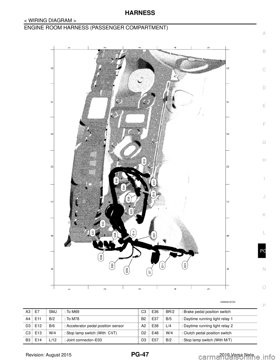
A 3 E 7 S M J : To M 6 9
C 3 E 3 6 BR/2 : Brake pedal position switch
A4 E11 B/2 : To M78 B2 E37 B/5 : Daytime running light relay 1
D3 E12 B/6 : Accelerator pedal position sensor A2 E38 L/4 : Daytime running light relay 2
C3 E13 W/4 : Stop lamp switch (With CVT) D2 E48 W/4 : Clutch pedal position switch
B3 E14 L/12 : Joint connector–E03 D3 E57 B/2 : Stop lamp switch (With M/T)
Revision: August 2015 2016 Versa Note
cardiagn.com
Page 3226 of 3641

STEERING WHEELST-5
< BASIC INSPECTION >
C
DE
F
H I
J
K L
M A
B
ST
N
O P
BASIC INSPECTION
STEERING WHEEL
InspectionINFOID:0000000012430497
CONDITION OF INSTALLATION
• Check installation conditions of steering gear, front suspension, axle and steering column.
• Check if movement exists when steering wheel is mo ved up and down, to the left and right and to the axial
direction.
• Verify that the steering gear nuts are tightened to specification. Refer to ST-14, "
Exploded View".
STEERING WHEEL PLAY
1. Set the front wheels and tires in the straight-ahead position, start engine, then lightly turn steering wheel
to the left and right until the front wheels start to move. Measure steering wheel movement on the outer
circumference.
2. When the measurement value is outside the standard va lue, check backlash for each joint of steering col-
umn and installation condition of steering gear.
STEERING WHEEL NEUTRAL POSITION
Check steering wheel neutral position using the following procedure:
1. Confirm that front wheel alignment is correct. Refer to FSU-8, "
Adjustment".
2. Set the front wheels and tires in the straight-ahead posit ion, check if steering wheel is in the neutral posi-
tion.
3. If it is not in the neutral position, remo ve steering wheel and reinstall it correctly.
4. If the neutral position cannot be attained by repositi oning the steering wheel two teeth or less on steering
stem, loosen the steering gear outer socket lock nuts, then adjust the inner sockets by the same amount
in the opposite direction.
5. Re-check the front wheel alignment. Refer to FSU-8, "
Adjustment".
STEERING WHEEL TURNING FORCE
1. Park vehicle on a level and dry surface, set parking brake.
2. Tires need to be inflated normal pressure. Refer to WT-54, "
Tire Air Pressure".
3. Start engine.
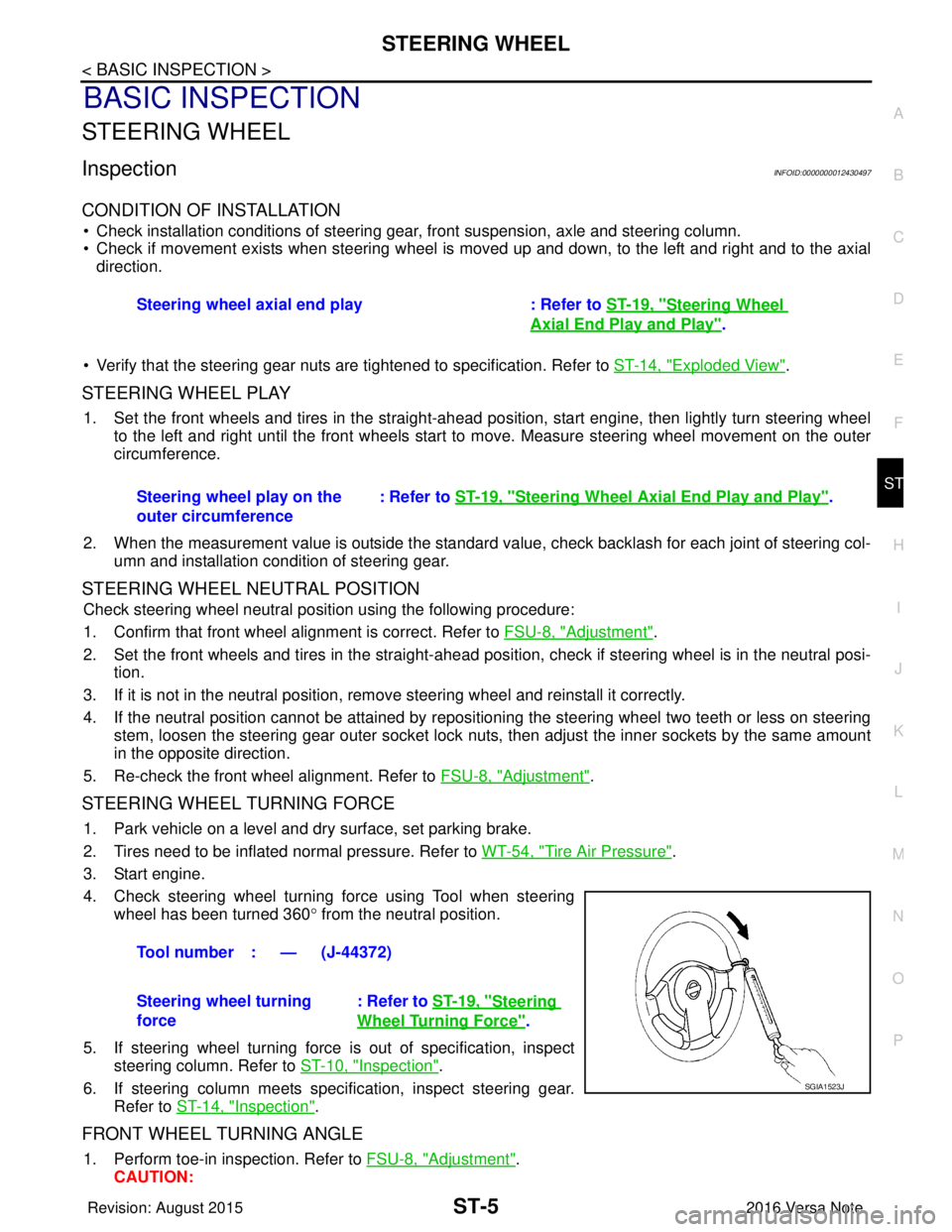
4. Check steering wheel turning force using Tool when steering wheel has been turned 360 ° from the neutral position.
5. If steering wheel turning force is out of specification, inspect steering column. Refer to ST-10, "
Inspection".
6. If steering column meets specification, inspect steering gear. Refer to ST-14, "
Inspection".
FRONT WHEEL TURNING ANGLE
1. Perform toe-in inspection. Refer to FSU-8, "Adjustment".
CAUTION: Steering wheel axial end play : Refer to
ST-19, "
Steering Wheel
Axial End Play and Play".
Steering wheel play on the
outer circumference : Refer to
ST-19, "
Steering Wheel Axia l End Play and Play".
Tool number : — (J-44372)
Steering wheel turning
force : Refer to
ST-19, "
Steering
Wheel Turning Force".
SGIA1523J
Revision: August 2015 2016 Versa Note
cardiagn.com
Page 3516 of 3641

WCS
WCS-1
DRIVER INFORMATION & MULTIMEDIA
C
DE
F
G H
I
J
K L
M B
SECTION WCS
A
O P
CONTENTS
WARNING CHIME SYSTEM
HOW TO USE THIS MANU AL ......................3
APPLICATION NOTICE ................................. .....3
Information .......................................................... ......3
PRECAUTION ...............................................4
PRECAUTIONS .............................................. .....4
Precaution for Supplemental Restraint System
(SRS) "AIR BAG" and "SEAT BELT PRE-TEN-
SIONER" ............................................................. ......
4
SYSTEM DESCRIPTION ..............................5
COMPONENT PARTS ................................... .....5
Component Parts Location .................................. ......5
Combination Meter ....................................................5
SYSTEM ..............................................................7
WARNING CHIME SYSTEM .......................................7
WARNING CHIME SYSTEM : System Description
......
7
WARNING CHIME SYSTEM : Fail-safe ....................8
LIGHT REMINDER WARNING CHIME ................. ......8
LIGHT REMINDER WARNING CHIME : Light Re-
minder Warning .........................................................
8
PARKING BRAKE RELEASE WARNING CHIME ......9
PARKING BRAKE RELEASE WARNING CHIME
: Parking Brake Release Warning Chime ............ ......
9
SEAT BELT REMINDER WARNING CHIME ........ ....10
SEAT BELT REMINDER WARNING CHIME :
Seat belt Warning ....................................................
10
KEY WARNING CHIME (WITHOUT INTELLIGENT
KEY) ....................................................................... ....
11
KEY WARNING CHIME (WITHOUT INTELLI-
GENT KEY) : Key Warning Chime ..........................
11
DIAGNOSIS SYSTEM (COMBINATION
METER) .............................................................
13
TYPE A ............................................ ...........................13
TYPE A : On Board Diagnosis Function .............. ....13
TYPE A : CONSULT Function (METER/M&A) ........14
TYPE B ............................................ ...........................16
TYPE B : On Board Diagnosis Function .............. ....16
TYPE B : CONSULT Function (METER/M&A) ........18
DIAGNOSIS SYSTEM (BCM) (WITH INTELLI-
GENT KEY SYSTEM) .......................................
21
COMMON ITEM ..................................................... ....21
COMMON ITEM : CONSULT Function (BCM -
COMMON ITEM) .....................................................
21
BUZZER ................................................................. ....22
BUZZER : CONSULT Function (BCM - BUZZER) ....22
DIAGNOSIS SYSTEM (BCM) (WITHOUT IN-
TELLIGENT KEY SYSTEM) .............................
23
COMMON ITEM ..................................................... ....23
COMMON ITEM : CONSULT Function (BCM -
COMMON ITEM) .....................................................
23
BUZZER ................................................................. ....24
BUZZER : CONSULT Function (BCM - BUZZER) ....24
ECU DIAGNOSIS INFORMATION ..............25
BCM, COMBINATION METER .........................25
List of ECU Reference ......................................... ....25
WIRING DIAGRAM ......................................26
WARNING CHIME SYSTEM .............................26
Wiring Diagram .................................................... ....26
BASIC INSPECTION ...................................32
DIAGNOSIS AND REPAIR WORK FLOW .......32
Revision: August 2015 2016 Versa Note
cardiagn.com
Page 3517 of 3641

WCS-2
Work Flow ...............................................................32
DTC/CIRCUIT DIAGNOSIS ...................... ...34
POWER SUPPLY AND GROUND CIRCUIT .. ...34
COMBINATION METER (TYPE A) ........................ ...34
COMBINATION METER (TYPE A) : Diagnosis
Procedure ............................................................ ...
34
COMBINATION METER (TYPE B) ........................ ...34
COMBINATION METER (TYPE B) : Diagnosis
Procedure ............................................................ ...
35
BCM (BODY CONTROL SYSTEM) (WITH INTEL-
LIGENT KEY SYSTEM) ..... .......................................
35
BCM (BODY CONTROL S YSTEM) (WITH INTEL-
LIGENT KEY SYSTEM) : Dia gnosis Procedure .....
35
BCM (BODY CONTROL SYST EM) (WITHOUT IN-
TELLIGENT KEY SYSTEM) . ....................................
36
BCM (BODY CONTROL SYSTEM) (WITHOUT
INTELLIGENT KEY SYSTEM) : Diagnosis Proce-
dure ..................................................................... ...
36
METER BUZZER CIRCUIT ................................38
Component Function Check ................................ ...38
Diagnosis Procedure .............................................38
SEAT BELT BUCKLE SWITCH SIGNAL CIR-
CUIT ...................................................................
39
TYPE A ................................................................... ...39
TYPE A : Description ..............................................39
TYPE A : Component Func tion Check ..................39
TYPE A : Diagnosis Procedu re ..............................39
TYPE A : Component Inspec tion ............................40
TYPE B ............... .................................................... ...40
TYPE B : Description ..............................................40
TYPE B : Component Func tion Check ..................40
TYPE B : Diagnosis Procedu re ..............................40
TYPE B : Component Inspec tion ............................41
PARKING BRAKE SWITCH SIGNAL CIR-
CUIT ................................................................ ...
42
TYPE A ............................................ ..........................42
TYPE A : Component Functi on Check ....................42
TYPE A : Diagnosis Procedur e ...............................42
TYPE A : Component Inspec tion ............................43
TYPE B ............ ................................ ..........................43
TYPE B : Component Functi on Check ....................43
TYPE B : Diagnosis Procedur e ...............................43
TYPE B : Component Inspec tion ............................44
KEY SWITCH SIGNAL CIRCUIT (WITHOUT
INTELLIGENT KEY) ....................................... ...
45
Description ........................................................... ...45
Component Function Check ..................................45
Diagnosis Procedure ..............................................45
Component Inspection ............................................46
SYMPTOM DIAGNOSIS ............................47
THE PARKING BRAKE RELEASE WARNING
CONTINUES SOUNDING, OR DOES NOT
SOUND ........................................................... ...
47
Description ........................................................... ...47
Diagnosis Procedure ...............................................47
THE SEAT BELT REMINDER WARNING
CONTINUES SOUNDING, OR DOES NOT
SOUND ..............................................................
48
Description ........................................................... ...48
Diagnosis Procedure ...............................................48
THE LIGHT REMINDER WARNING DOES
NOT SOUND ......................................................
49
Description ........................................................... ...49
Diagnosis Procedure ...............................................49
THE KEY WARNING DOES NOT SOUND
(WITHOUT INTELLIGENT KEY) .......................
50
Description ..............................................................50
Diagnosis Procedure ...............................................50
Revision: August 2015 2016 Versa Note
cardiagn.com
Page 3520 of 3641

WCS
COMPONENT PARTSWCS-5
< SYSTEM DESCRIPTION >
C
DE
F
G H
I
J
K L
M B A
O P
SYSTEM DESCRIPTION
COMPONENT PARTS
Component Parts LocationINFOID:0000000012432667
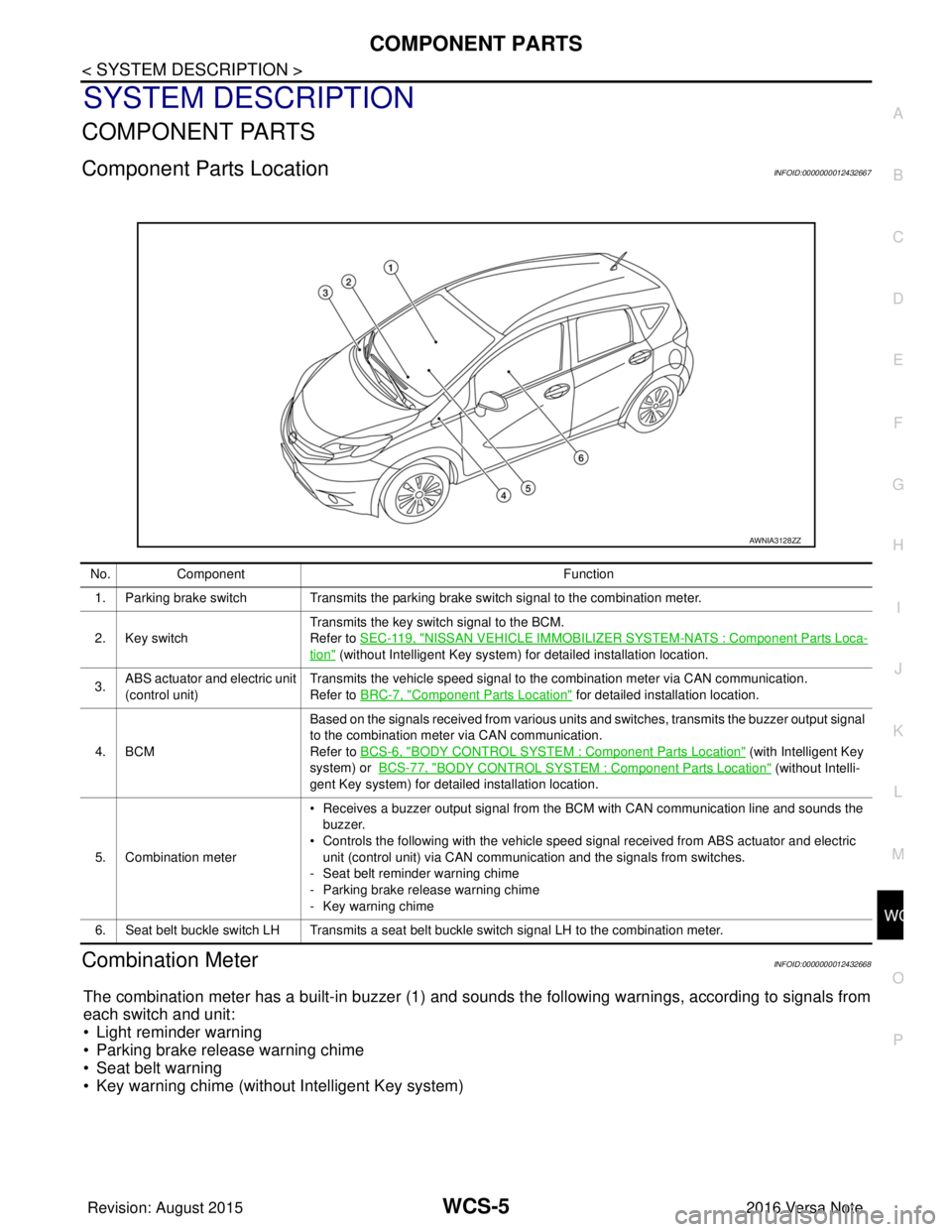
Combination MeterINFOID:0000000012432668
The combination meter has a built-in buzzer (1) and sounds the following warnings, according to signals from
each switch and unit:
• Light reminder warning
• Parking brake release warning chime
• Seat belt warning
• Key warning chime (without Intelligent Key system)
AWNIA3128ZZ
No. Component Function
1. Parking brake switch Transmits the parking brake switch signal to the combination meter.
2. Key switch Transmits the key switch signal to the BCM.
Refer to
SEC-119, "
NISSAN VEHICLE IMMOBILIZER SYSTEM -NATS : Component Parts Loca-
tion" (without Intelligent Key system) for detailed installation location.
3. ABS actuator and electric unit
(control unit) Transmits the vehicle speed signal to the combination meter via CAN communication.
Refer to BRC-7, "
Component Parts Location" for detailed installation location.
4. BCM Based on the signals received from various units and switches, transmits the buzzer output signal
to the combination meter via CAN communication.
Refer to BCS-6, "
BODY CONTROL SYSTEM : Co
mponent Parts Location" (with Intelligent Key
system) or BCS-77, "
BODY CONTROL SYSTEM : Component Parts Location" (without Intelli-
gent Key system) for detailed installation location.
5. Combination meter • Receives a buzzer output signal from the BCM with CAN communication line and sounds the
buzzer.
• Controls the following with the vehicle speed signal received from ABS actuator and electric
unit (control unit) via CAN communication and the signals from switches.
- Seat belt reminder warning chime
- Parking brake release warning chime
- Key warning chime
6. Seat belt buckle switch LH Transmits a seat belt buckle switch signal LH to the combination meter.
Revision: August 2015 2016 Versa Note
cardiagn.com