2016 NISSAN NOTE ECU
[x] Cancel search: ECUPage 1637 of 3641
![NISSAN NOTE 2016 Service Repair Manual ENGINE OILLU-7
< PERIODIC MAINTENANCE > [HR16DE]
C
D
E
F
G H
I
J
K L
M A
LU
NP
O
PERIODIC MAINTENANCE
ENGINE OIL
InspectionINFOID:0000000012432200
ENGINE OIL LEVEL
NOTE:
Before starting engine, positi NISSAN NOTE 2016 Service Repair Manual ENGINE OILLU-7
< PERIODIC MAINTENANCE > [HR16DE]
C
D
E
F
G H
I
J
K L
M A
LU
NP
O
PERIODIC MAINTENANCE
ENGINE OIL
InspectionINFOID:0000000012432200
ENGINE OIL LEVEL
NOTE:
Before starting engine, positi](/manual-img/5/57363/w960_57363-1636.png)
ENGINE OILLU-7
< PERIODIC MAINTENANCE > [HR16DE]
C
D
E
F
G H
I
J
K L
M A
LU
NP
O
PERIODIC MAINTENANCE
ENGINE OIL
InspectionINFOID:0000000012432200
ENGINE OIL LEVEL
NOTE:
Before starting engine, position the vehicle so that it
is level and check the engine oil level. If engine is already
started, stop it and allow 10 minutes before checking.
1. Pull out oil level gauge and wipe it clean.
2. Insert oil level gauge and check that the engine oil level is within the range (A) as shown.
3. If it is out of range, adjust it.
ENGINE OIL APPEARANCE
• Check engine oil for white milky appearance or excessive contamination.
• If engine oil becomes turbid and white, it is highly probable that it is contaminated with engine coolant. Repair or replace damaged parts.
ENGINE OIL LEAKS
Check for engine oil leaks around the following areas:
• Oil pan (upper and lower)
• Oil pan drain plug
• Oil pressure sensor
• Oil filter
• Oil cooler
• Oil level sensor
• Engine oil temperature sensor
• Intake valve timing control solenoid valve
• Exhaust valve timing control solenoid valve
• Mating surface between front cover and rocker cover
• Mating surface between cylinder block and cylinder head
• Mating surface between cylinder head and rocker cover
• Crankshaft oil seals (front and rear)
• Front cover
ENGINE OIL PRESSURE CHECK
WARNING:
• Be careful not to burn yoursel f, as engine oil may be hot.
• When checking engine oil pressure, sh ift selector should be in the "P" (Park) or "N" (Neutral) posi-
tion, and apply parking brake securely.
1. Check engine oil level.
JPBIA0554ZZ
Revision: August 2015 2016 Versa Note
cardiagn.com
Page 1651 of 3641

EX-6
< REMOVAL AND INSTALLATION >
EXHAUST SYSTEM
INSTALLATION
Installation is in the reverse order of removal.
CAUTION:
• Do not reuse gasket.
• Do not reuse seal bearing.
• Discard any heated oxygen sensor 2 which has been dropped from a height of more than 0.5 m (19.7
in) onto a hard surface such as a concrete floor. Use a new one.
• Before installing a new heated o xygen sensor 2, clean exhaust system threads using a suitable tool
and apply anti-seize lubricant.
• Do not over tighten heated oxygen sensor 2. Doin g so may cause damage to the heated oxygen sen-
sor 2, resulting in the “MIL” coming on.
• Prevent rust preventives from adhering to the sensor body.
• If heat insulator is badly deformed, repair or re place it. If deposits such as mud pile up on the heat
insulator, remove them.
• When installing heat insulator avoid large gaps or interference between heat insulator and each
exhaust pipe.
• Remove deposits from the sealing surface of each connection. Connect them securely to avoid
exhaust gas leaks.
• When installing each mounting rubber, use silicon oil to avoid twisting.
• Temporarily tighten nuts and bolts. Check each part for unusual interference and mounting rubber interference, and then tighten them to the specified torque.
• When installing each mounting rubber, avoid twisting or unus ual extension in up/down, front/rear
and right/left directions.
Exhaust Manifold to Exhaust Front Tube
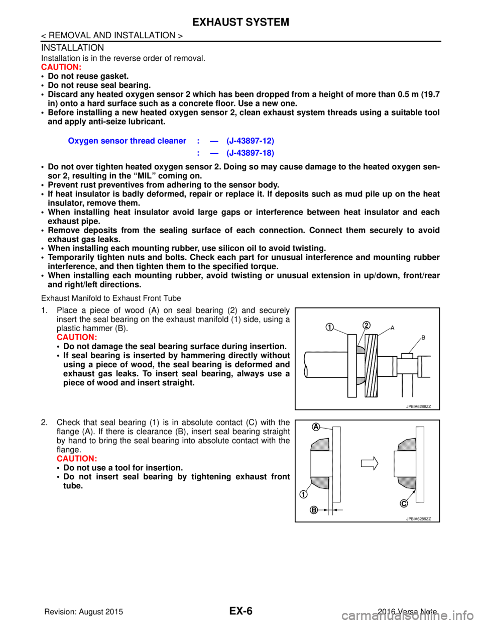
1. Place a piece of wood (A) on seal bearing (2) and securely insert the seal bearing on the exhaust manifold (1) side, using a
plastic hammer (B).
CAUTION:
• Do not damage the seal bearing surface during insertion.
• If seal bearing is inserted by hammering directly without
using a piece of wood, the seal bearing is deformed and
exhaust gas leaks. To insert seal bearing, always use a
piece of wood and insert straight.
2. Check that seal bearing (1) is in absolute contact (C) with the flange (A). If there is clearance (B), insert seal bearing straight
by hand to bring the seal bearing into absolute contact with the
flange.
CAUTION:
• Do not use a tool for insertion.
• Do not insert seal bearing by tightening exhaust front
tube. Oxygen sensor thread cleaner : — (J-43897-12)
: — (J-43897-18)
JPBIA6288ZZ
JPBIA6289ZZ
Revision: August 2015 2016 Versa Note
cardiagn.com
Page 1652 of 3641

EXHAUST SYSTEMEX-7
< REMOVAL AND INSTALLATION >
C
DE
F
G H
I
J
K L
M A
EX
NP
O
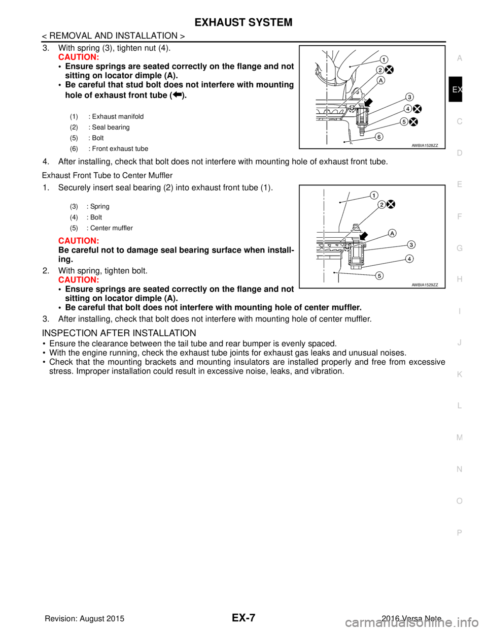
3. With spring (3), tighten nut (4).
CAUTION:
• Ensure springs are seated correctly on the flange and notsitting on locator dimple (A).
• Be careful that stud bolt do es not interfere with mounting
hole of exhaust front tube ( ).
4. After installing, check that bolt does not in terfere with mounting hole of exhaust front tube.
Exhaust Front Tube to Center Muffler
1. Securely insert seal bearing (2) into exhaust front tube (1).
CAUTION:
Be careful not to damage seal bearing surface when install-
ing.
2. With spring, tighten bolt. CAUTION:
• Ensure springs are seated correctly on the flange and notsitting on locator dimple (A).
• Be careful that bolt does not interfere with mounting hole of center muffler.
3. After installing, check that bolt does not in terfere with mounting hole of center muffler.
INSPECTION AFTER INSTALLATION
• Ensure the clearance between the tail tube and rear bumper is evenly spaced.
• With the engine running, check the exhaust tube joints for exhaust gas leaks and unusual noises.
• Check that the mounting brackets and mounting insula tors are installed properly and free from excessive
stress. Improper installation could result in excessive noise, leaks, and vibration.
(1) : Exhaust manifold
(2) : Seal bearing
(5) : Bolt
(6) : Front exhaust tube
AWBIA1528ZZ
(3) : Spring
(4) : Bolt
(5) : Center muffler
AWBIA1529ZZ
Revision: August 2015 2016 Versa Note
cardiagn.com
Page 1654 of 3641

EXL-2
FLASHER : CONSULT Function (BCM - FLASH-
ER) .........................................................................
17
COMB SW .............................................................. ...18
COMB SW : CONSULT Function (BCM - COMB
SW) .........................................................................
18
BATTERY SAVER ................................................. ...18
BATTERY SAVER : CONSULT Function (BCM -
BATTERY SAVER) .................................................
18
DIAGNOSIS SYSTEM (IPDM E/R) ................. ...20
Diagnosis Description .......................................... ...20
CONSULT Function (IPDM E/R) ............................21
ECU DIAGNOSIS INFORMATION ..............24
BCM, IPDM E/R .............................................. ...24
List of ECU Reference ......................................... ...24
WIRING DIAGRAM .....................................25
HEADLAMP .................................................... ...25
Wiring Diagram - For USA ................................... ...25
Wiring Diagram - For Canada .................................31
DAYTIME LIGHT SYSTEM ............................. ...37
Wiring Diagram .................................................... ...37
FRONT FOG LAMP ...........................................43
Wiring Diagram .................................................... ...43
TURN SIGNAL AND HAZARD WARNING
LAMP SYSTEM .............................................. ...
48
Wiring Diagram .................................................... ...48
PARKING, LICENSE PLATE AND TAIL
LAMPS SYSTEM ............................................ ...
55
Wiring Diagram .................................................... ...55
STOP LAMP ......................................................63
Wiring Diagram .................................................... ...63
BACK-UP LAMP ................................................67
Wiring Diagram .................................................... ...67
BASIC INSPECTION ...................................71
DIAGNOSIS AND REPAIR WORKFLOW ...... ...71
Work Flow ............................................................ ...71
DTC/CIRCUIT DIAGNOSIS ...................... ...74
POWER SUPPLY AND GROUND CIRCUIT .. ...74
BCM (BODY CONTROL SYSTEM) (WITH INTEL-
LIGENT KEY SYSTEM) ..... .......................................
74
BCM (BODY CONTROL S YSTEM) (WITH INTEL-
LIGENT KEY SYSTEM) : Dia gnosis Procedure .....
74
BCM (BODY CONTROL SYST EM) (WITHOUT IN-
TELLIGENT KEY SYSTEM) . ....................................
74
BCM (BODY CONTROL SYSTEM) (WITHOUT
INTELLIGENT KEY SYSTEM) : Diagnosis Proce-
dure ...................................................................... ...
74
IPDM E/R ................................................................ ...75
IPDM E/R : Diagnosis Procedure ............................75
HEADLAMP (HI) CIRCUIT ................................77
Description ........................................................... ...77
Component Function Check ...................................77
Diagnosis Procedure ...............................................77
HEADLAMP (LO) CIRCUIT ...............................79
Description ........................................................... ...79
Component Function Check ...................................79
Diagnosis Procedure ...............................................79
PARKING LAMP CIRCUIT ................................82
Description ........................................................... ...82
Component Function Check ...................................82
Diagnosis Procedure ...............................................82
TURN SIGNAL LAMP CIRCUIT ........................85
Description ........................................................... ...85
Component Function Check ...................................85
Diagnosis Procedure ...............................................85
FRONT FOG LAMP CIRCUIT ...........................88
Component Function Check ................................ ...88
Diagnosis Procedure ...............................................88
Component Inspection ............................................90
SYMPTOM DIAGNOSIS ............................91
EXTERIOR LIGHTING SYSTEM SYMPTOMS ...91
Symptom Table .................................................... ...91
BOTH SIDE HEADLAMPS DO NOT SWITCH
TO HIGH BEAM .................................................
93
Description ........................................................... ...93
Diagnosis Procedure ...............................................93
BOTH SIDE HEADLAMPS (LO) ARE NOT
TURNED ON ......................................................
94
Description ..............................................................94
Diagnosis Procedure ...............................................94
PARKING, LICENSE PLATE AND TAIL
LAMPS ARE NOT TURNED ON .......................
95
Description ........................................................... ...95
Diagnosis Procedure ...............................................95
BOTH SIDE FRONT FOG LAMPS ARE NOT
TURNED ON ......................................................
96
Description ..............................................................96
Diagnosis Procedure ...............................................96
PERIODIC MAINTENANCE .......................97
HEADLAMP AIMING ADJUSTMENT ............ ...97
Inspection ............................................................. ...97
Aiming Adjustment Procedure ................................98
Revision: August 2015 2016 Versa Note
cardiagn.com
Page 1656 of 3641

EXL-4
< PRECAUTION >
PRECAUTIONS
PRECAUTION
PRECAUTIONS
Precaution for Supplemental Restraint System (SRS) "AIR BAG" and "SEAT BELT
PRE-TENSIONER"
INFOID:0000000012432764
The Supplemental Restraint System such as “A IR BAG” and “SEAT BELT PRE-TENSIONER”, used along
with a front seat belt, helps to reduce the risk or severity of injury to the driver and front passenger for certain
types of collision. Information necessary to service the system safely is included in the SR and SB section of
this Service Manual.
WARNING:
• To avoid rendering the SRS inopera tive, which could increase the risk of personal injury or death in
the event of a collision which would result in air bag inflation, all maintenance must be performed by
an authorized NISSAN/INFINITI dealer.
• Improper maintenance, including in correct removal and installation of the SRS, can lead to personal
injury caused by unintent ional activation of the system. For re moval of Spiral Cable and Air Bag
Module, see the SR section.
• Do not use electrical test equipmen t on any circuit related to the SRS unless instructed to in this
Service Manual. SRS wiring harn esses can be identified by yellow and/or orange harnesses or har-
ness connectors.
PRECAUTIONS WHEN USING POWER TOOLS (AIR OR ELECTRIC) AND HAMMERS
WARNING:
• When working near the Airbag Diagnosis Sensor Unit or other Airbag System sensors with the Igni-
tion ON or engine running, DO NOT use air or electri c power tools or strike near the sensor(s) with a
hammer. Heavy vibration could activate the sensor( s) and deploy the air bag(s), possibly causing
serious injury.
• When using air or electric power tools or hammers , always switch the Ignition OFF, disconnect the
battery and wait at least three minutes before performing any service.
Precaution for WorkINFOID:0000000012432765
• When removing or disassembling each component, be careful not to damage or deform it. If a component may be subject to interference, be sure to protect it with a shop cloth.
• When removing (disengaging) components with a screwdriver or similar tool, be sure to wrap the component with a shop cloth or vinyl tape to protect it.
• Protect the removed parts with a shop cloth and prevent them from being dropped.
• Replace a deformed or damaged clip.
• If a part is specified as a non-reusable part, always replace it with a new one.
• Be sure to tighten bolts and nuts securely to the specified torque.
• After installation is complete, be sure to check that each part works properly.
• Follow the steps below to clean components:
- Water soluble dirt:
• Dip a soft cloth into lukewarm water, wring the water out of the cloth and wipe the dirty area.
• Then rub with a soft, dry cloth.
- Oily dirt:
• Dip a soft cloth into lukewarm water with mild detergent (concentration: within 2 to 3%) and wipe the dirty area.
• Then dip a cloth into fresh water, wring the water out of the cloth and wipe the detergent off.
• Then rub with a soft, dry cloth.
- Do not use organic solvent such as thinner, benzene, alcohol or gasoline.
- For genuine leather seats, use a genuine leather seat cleaner.
Revision: August 2015 2016 Versa Note
cardiagn.com
Page 1664 of 3641

EXL-12
< SYSTEM DESCRIPTION >
DIAGNOSIS SYSTEM (BCM) (WITH INTELLIGENT KEY SYSTEM)
DIAGNOSIS SYSTEM (BCM) (WITH INTELLIGENT KEY SYSTEM)
COMMON ITEM
COMMON ITEM : CONSULT Function (BCM - COMMON ITEM)INFOID:0000000012542302
APPLICATION ITEM
CONSULT performs the following functions via CAN communication with BCM.
SYSTEM APPLICATION
BCM can perform the following functions.
Direct Diagnostic Mode Description
ECU Identification The BCM part number is displayed.
Self Diagnostic Result The BCM self diagnostic results are displayed.
Data Monitor The BCM input/output data is displayed in real time.
Active Test The BCM activates outputs to test components.
Work support The settings for BCM functions can be changed.
Configuration • The vehicle specification can be read and saved.
• The vehicle specification can be written when replacing BCM.
CAN DIAG SUPPORT MNTR The result of transmit/receive diagnosis of CAN communication is displayed.
System Sub System Direct Diagnostic Mode
ECU Identification
Self Diagnostic Result
Data Monitor
Active Test
Work support
Configuration
CAN DIAG SUPPORT MNTR
Door lock
DOOR LOCK ×××
Rear window defogger REAR DEFOGGER ××
Warning chime BUZZER ××
Interior room lamp timer INT LAMP ×××
Exterior lamp HEAD LAMP ×××
Wiper and washer WIPER ×××
Turn signal and hazard warning lamps FLASHER ×××
Air conditioner AIR CONDITIONER ×
Intelligent Key system INTELLIGENT KEY ××××
Combination switch COMB SW ×
BCM BCM× × ×××
Immobilizer IMMU ××××
Interior room lamp battery saver BATTERY SAVER ×××
Vehicle security system THEFT ALM ××
RAP system RETAINED PWR ×
Signal buffer system SIGNAL BUFFER ×
TPMS AIR PRESSURE MONITOR ××××
Panic alarm system PANIC ALARM ×
Revision: August 2015 2016 Versa Note
cardiagn.com
Page 1668 of 3641

EXL-16
< SYSTEM DESCRIPTION >
DIAGNOSIS SYSTEM (BCM) (WITHOUT INTELLIGENT KEY SYSTEM)
DIAGNOSIS SYSTEM (BCM) (WITHOUT INTELLIGENT KEY SYSTEM)
COMMON ITEM
COMMON ITEM : CONSULT Function (BCM - COMMON ITEM)INFOID:0000000012542311
APPLICATION ITEM
CONSULT performs the following functions via CAN communication with BCM.
SYSTEM APPLICATION
BCM can perform the following functions.
Direct Diagnostic Mode Description
ECU Identification The BCM part number is displayed.
Self Diagnostic Result The BCM self diagnostic results are displayed.
Data Monitor The BCM input/output data is displayed in real time.
Active Test The BCM activates outputs to test components.
Work support The settings for BCM functions can be changed.
Configuration • The vehicle specification can be read and saved.
• The vehicle specification can be written when replacing BCM.
CAN DIAG SUPPORT MNTR The result of transmit/receive diagnosis of CAN communication is displayed.
System Sub System Direct Diagnostic Mode
ECU Identification
Self Diagnostic Result
Data Monitor
Active Test
Work support
Configuration
CAN DIAG SUPPORT MNTR
Door lock
DOOR LOCK ×××
Rear window defogger REAR DEFOGGER ××
Warning chime BUZZER ××
Interior room lamp timer INT LAMP ×××
Remote keyless entry system MULTI REMOTE ENT ×××
Exterior lamp HEAD LAMP ×××
Wiper and washer WIPER ×××
Turn signal and hazard warning lamps FLASHER ××
Air conditioner AIR CONDITIONER ×
Combination switch COMB SW ×
BCM BCM× × ×××
Immobilizer IMMU ×××
Interior room lamp battery saver BATTERY SAVER ×××
Vehicle security system THEFT ALM ××
RAP system RETAINED PWR ××
Signal buffer system SIGNAL BUFFER ×
TPMS AIR PRESSURE MONITOR ××××
Panic alarm system PANIC ALARM ×
Revision: August 2015 2016 Versa Note
cardiagn.com
Page 1673 of 3641

DIAGNOSIS SYSTEM (IPDM E/R)EXL-21
< SYSTEM DESCRIPTION >
C
DE
F
G H
I
J
K
M A
B
EXL
N
O P
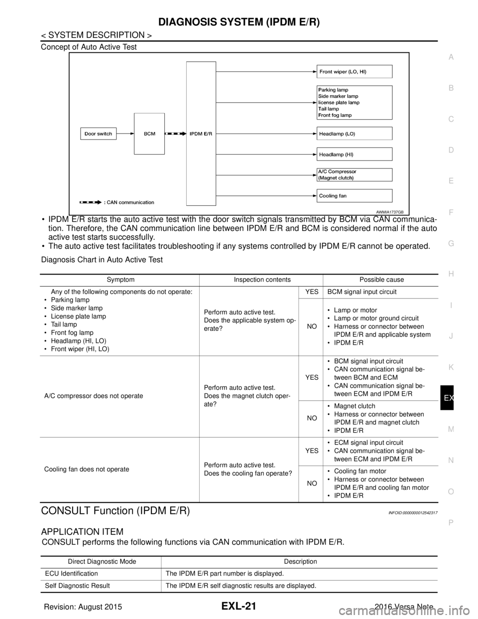
Concept of Auto Active Test
• IPDM E/R starts the auto active test with the door
switch signals transmitted by BCM via CAN communica-
tion. Therefore, the CAN communication line between IPDM E/R and BCM is considered normal if the auto
active test starts successfully.
• The auto active test facilitates troubleshooting if any systems controlled by IPDM E/R cannot be operated.
Diagnosis Chart in Auto Active Test
CONSULT Function (IPDM E/R)INFOID:0000000012542317
APPLICATION ITEM
CONSULT performs the following functions via CAN communication with IPDM E/R.
AWMIA1737GB
SymptomInspection contentsPossible cause
Any of the following components do not operate:
•Parking lamp
• Side marker lamp
• License plate lamp
•Tail lamp
•Front fog lamp
• Headlamp (HI, LO)
• Front wiper (HI, LO) Perform auto active test.
Does the applicable system op-
erate?YES BCM signal input circuit
NO • Lamp or motor
• Lamp or motor ground circuit
• Harness or connector between
IPDM E/R and applicable system
•IPDM E/R
A/C compressor does not operate Perform auto active test.
Does the magnet clutch oper-
ate?YES
• BCM signal input circuit
• CAN communication signal be-
tween BCM and ECM
• CAN communication signal be-
tween ECM and IPDM E/R
NO • Magnet clutch
• Harness or connector between
IPDM E/R and magnet clutch
•IPDM E/R
Cooling fan does not operate Perform auto active test.
Does the cooling fan operate?YES
• ECM signal input circuit
• CAN communication signal be-
tween ECM and IPDM E/R
NO • Cooling fan motor
• Harness or connector between
IPDM E/R and cooling fan motor
•IPDM E/R
Direct Diagnostic Mode Description
ECU Identification The IPDM E/R part number is displayed.
Self Diagnostic Result The IPDM E/R self diagnostic results are displayed.
Revision: August 2015 2016 Versa Note
cardiagn.com