2016 NISSAN NOTE ECU
[x] Cancel search: ECUPage 1868 of 3641
FL-2
< PRECAUTION >
PRECAUTIONS
PRECAUTION
PRECAUTIONS
Precaution for Supplemental Restraint System (SRS) "AIR BAG" and "SEAT BELT
PRE-TENSIONER"
INFOID:0000000012432103
The Supplemental Restraint System such as “A IR BAG” and “SEAT BELT PRE-TENSIONER”, used along
with a front seat belt, helps to reduce the risk or severity of injury to the driver and front passenger for certain
types of collision. Information necessary to service the system safely is included in the SR and SB section of
this Service Manual.
WARNING:
• To avoid rendering the SRS inopera tive, which could increase the risk of personal injury or death in
the event of a collision which would result in air bag inflation, all maintenance must be performed by
an authorized NISSAN/INFINITI dealer.
• Improper maintenance, including in correct removal and installation of the SRS, can lead to personal
injury caused by unintent ional activation of the system. For re moval of Spiral Cable and Air Bag
Module, see the SR section.
• Do not use electrical test equipmen t on any circuit related to the SRS unless instructed to in this
Service Manual. SRS wiring harn esses can be identified by yellow and/or orange harnesses or har-
ness connectors.
PRECAUTIONS WHEN USING POWER TOOLS (AIR OR ELECTRIC) AND HAMMERS
WARNING:
• When working near the Airbag Diagnosis Sensor Unit or other Airbag System sensors with the Igni-
tion ON or engine running, DO NOT use air or electri c power tools or strike near the sensor(s) with a
hammer. Heavy vibration could activate the sensor( s) and deploy the air bag(s), possibly causing
serious injury.
• When using air or electric power tools or hammers , always switch the Ignition OFF, disconnect the
battery and wait at least three minutes before performing any service.
General PrecautionINFOID:0000000012432104
WARNING:
When replacing fuel line parts, be sure to observe the following.
• Put a “CAUTION: FLAMMABLE” sign in the work area.
• Be sure to work in a well ventilated area and have a CO
2 fire extinguisher.
• Do not smoke while working on the fuel system. Keep open flames and sparks away from the work
area.
CAUTION:
• Before removing fuel line parts, carry out the following procedures:
- Put drained fuel in an explosi on-proof container and put the lid on securely. Keep the container in
safe area.
- Release fuel pressure from the fuel lines. Refer to EC-1
37, "Work Procedure" .
- Disconnect the battery ground
cable.
• Always replace O-rings and clamps with new ones.
• Do not kink or twist tubes when they are being installed.
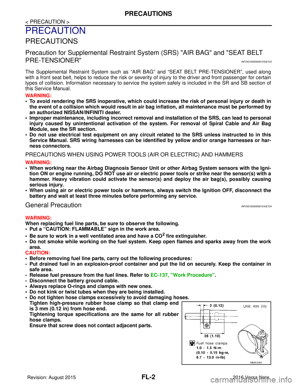
• Do not tighten hose clamps excessi vely to avoid damaging hoses.
Tighten high-pressure rubber hose clamp so that clamp end
is 3 mm (0.12 in) from hose end.
Tightening torque specificati ons are the same for all rubber
hose clamps.
Ensure that screw does not contact adjacent parts.
MMA104A
Revision: August 2015 2016 Versa Note
cardiagn.com
Page 1869 of 3641
PRECAUTIONSFL-3
< PRECAUTION >
C
DE
F
G H
I
J
K L
M A
FL
NP
O
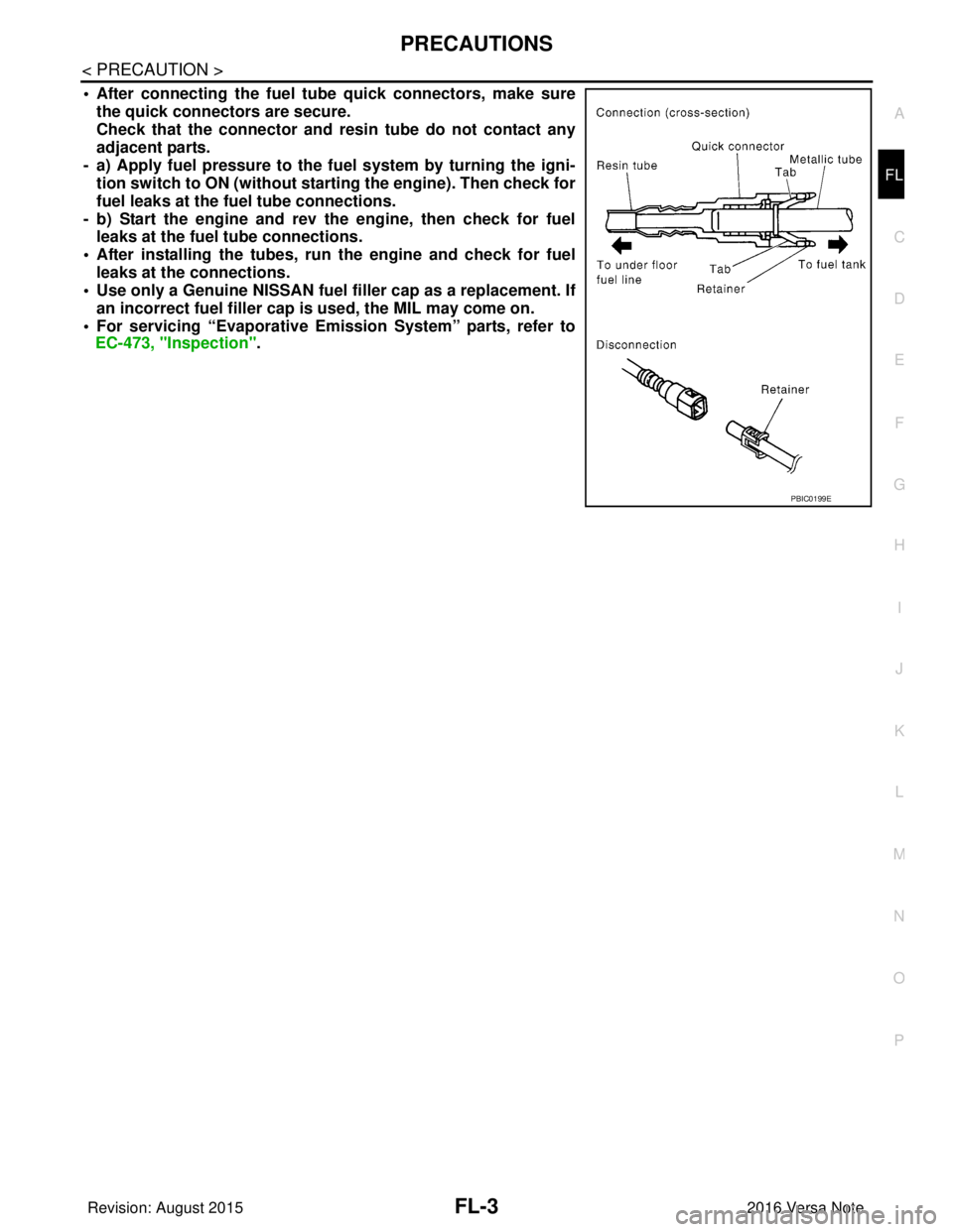
• After connecting the fuel tu
be quick connectors, make sure
the quick connectors are secure.
Check that the connector and r esin tube do not contact any
adjacent parts.
- a) Apply fuel pressure to the fu el system by turning the igni-
tion switch to ON (without starting the engine). Then check for
fuel leaks at the fuel tube connections.
- b) Start the engine and rev the engine, then check for fuel leaks at the fuel tube connections.
• After installing the tubes, run the engine and check for fuel
leaks at the connections.
• Use only a Genuine NISSAN fuel filler cap as a replacement. If
an incorrect fuel fi ller cap is used, the MIL may come on.
• For servicing “Evaporative Emi ssion System” parts, refer to
EC-473, "Inspection".
PBIC0199E
Revision: August 2015 2016 Versa Note
cardiagn.com
Page 1874 of 3641
FL -8
< REMOVAL AND INSTALLATION >
FUEL LEVEL SENSOR UNIT, FUEL FILTER AND FUEL PUMP ASSEMBLY
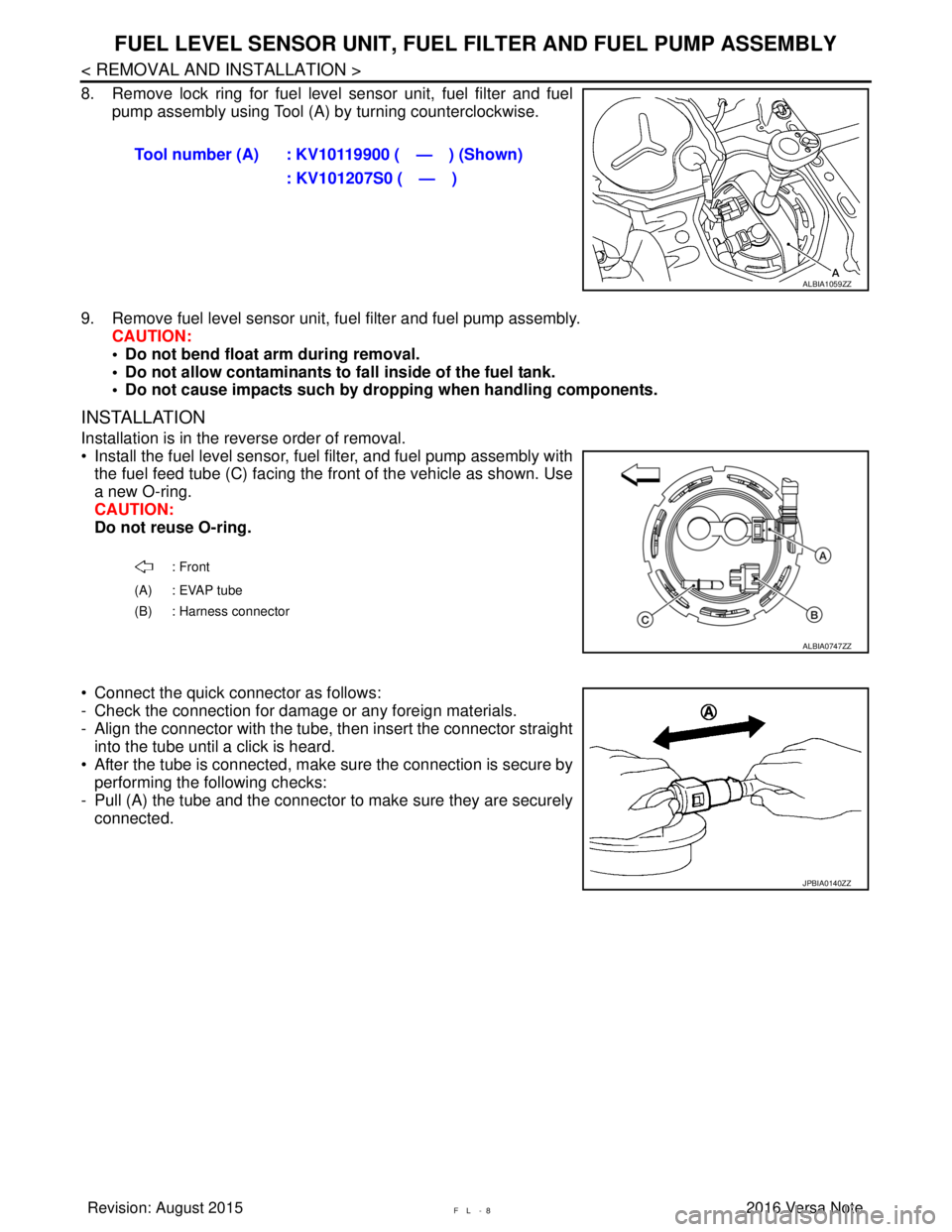
8. Remove lock ring for fuel level sensor unit, fuel filter and fuel
pump assembly using Tool (A) by turning counterclockwise.
9. Remove fuel level sensor unit, fuel filter and fuel pump assembly. CAUTION:
• Do not bend float arm during removal.
• Do not allow contaminants to fa ll inside of the fuel tank.
• Do not cause impacts such by dro pping when handling components.
INSTALLATION
Installation is in the reverse order of removal.
• Install the fuel level sensor, fuel filter, and fuel pump assembly with
the fuel feed tube (C) facing the front of the vehicle as shown. Use
a new O-ring.
CAUTION:
Do not reuse O-ring.
• Connect the quick connector as follows:
- Check the connection for damage or any foreign materials.
- Align the connector with the tube, then insert the connector straight into the tube until a click is heard.
• After the tube is connected, make sure the connection is secure by performing the following checks:
- Pull (A) the tube and the connector to make sure they are securely
connected. Tool number (A) : KV10119900 ( — ) (Shown)
: KV101207S0 ( — )
ALBIA1059ZZ
: Front
(A) : EVAP tube
(B) : Harness connector
ALBIA0747ZZ
JPBIA0140ZZ
Revision: August 2015 2016 Versa Note
cardiagn.com
Page 1878 of 3641
FL-12
< REMOVAL AND INSTALLATION >
FUEL TANK
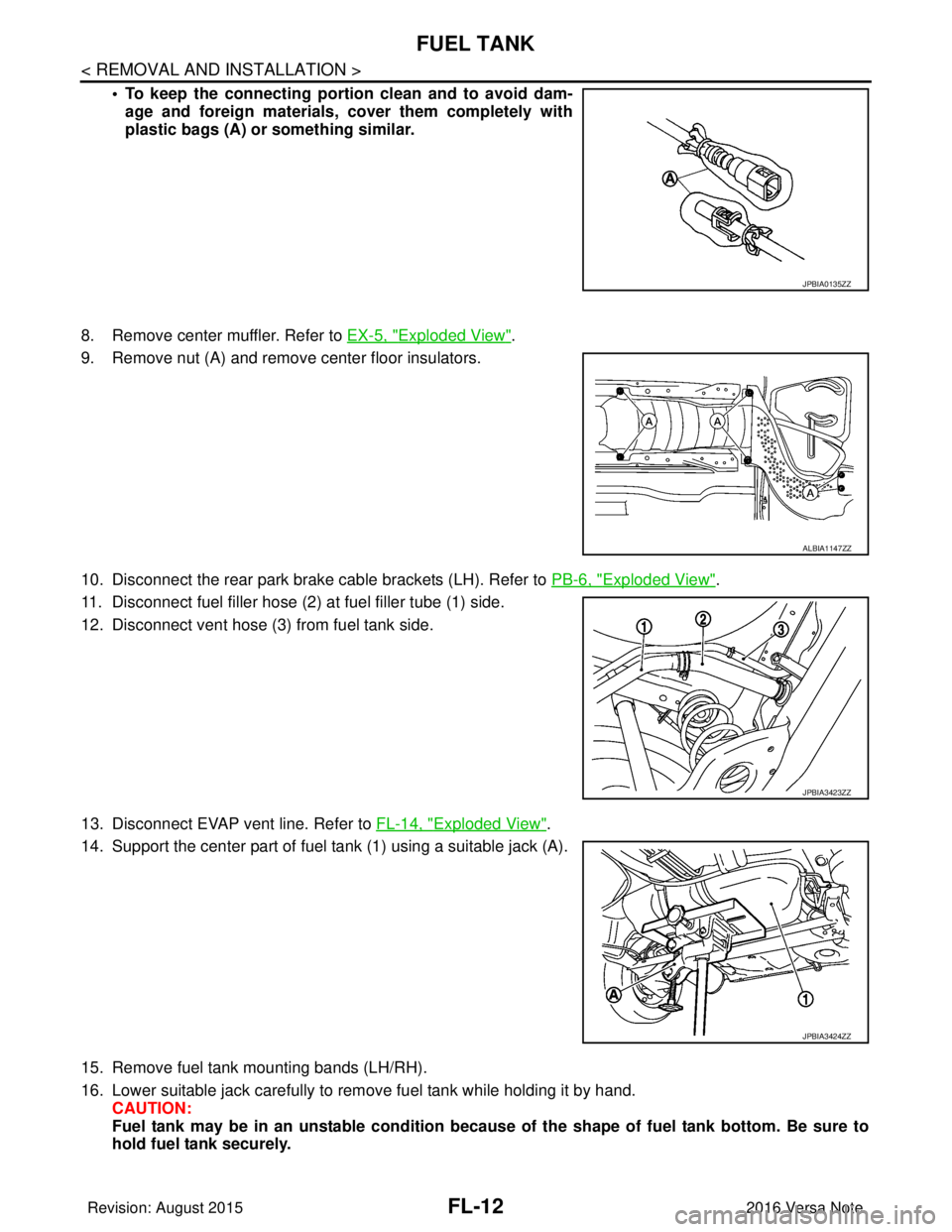
• To keep the connecting portion clean and to avoid dam-
age and foreign materials, cover them completely with
plastic bags (A) or something similar.
8. Remove center muffler. Refer to EX-5, "
Exploded View".
9. Remove nut (A) and remove center floor insulators.
10. Disconnect the rear park brake cable brackets (LH). Refer to PB-6, "
Exploded View".
11. Disconnect fuel filler hose (2) at fuel filler tube (1) side.
12. Disconnect vent hose (3) from fuel tank side.
13. Disconnect EVAP vent line. Refer to FL-14, "
Exploded View".
14. Support the center part of fuel tank (1) using a suitable jack (A).
15. Remove fuel tank mounting bands (LH/RH).
16. Lower suitable jack carefully to remove fuel tank while holding it by hand. CAUTION:
Fuel tank may be in an unstable condition because of the shape of fuel tank bottom. Be sure to
hold fuel tank securely.
JPBIA0135ZZ
ALBIA1147ZZ
JPBIA3423ZZ
JPBIA3424ZZ
Revision: August 2015 2016 Versa Note
cardiagn.com
Page 1914 of 3641
GI-26
< PRECAUTION >
PRECAUTIONS
• U.S. government regulations require ethanol dispensing pumps to be identified by a small, square,
orange and black label with the common abbreviation or the appropriate percentage for that region.
Multiport Fuel Injection System or Engine Control SystemINFOID:0000000012433165
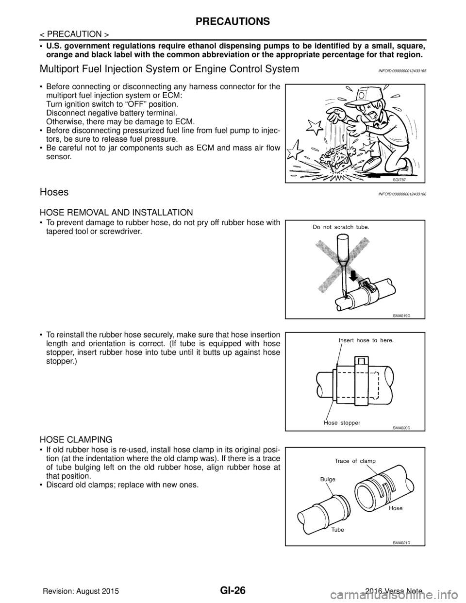
• Before connecting or disconnecting any harness connector for the
multiport fuel injection system or ECM:
Turn ignition switch to “OFF” position.
Disconnect negative battery terminal.
Otherwise, there may be damage to ECM.
• Before disconnecting pressurized fuel line from fuel pump to injec- tors, be sure to release fuel pressure.
• Be careful not to jar components such as ECM and mass air flow sensor.
HosesINFOID:0000000012433166
HOSE REMOVAL AND INSTALLATION
• To prevent damage to rubber hose, do not pry off rubber hose withtapered tool or screwdriver.
• To reinstall the rubber hose securely, make sure that hose insertion length and orientation is correct. (If tube is equipped with hose
stopper, insert rubber hose into tube until it butts up against hose
stopper.)
HOSE CLAMPING
• If old rubber hose is re-used, install hose clamp in its original posi-tion (at the indentation where the old clamp was). If there is a trace
of tube bulging left on the old rubber hose, align rubber hose at
that position.
• Discard old clamps; replace with new ones.
SGI787
SMA019D
SMA020D
SMA021D
Revision: August 2015 2016 Versa Note
cardiagn.com
Page 1919 of 3641
TOW TRUCK TOWINGGI-31
< PRECAUTION >
C
DE
F
G H
I
J
K L
M B
GI
N
O PTOW TRUCK TOWING
To w T r u c k To w i n gINFOID:0000000012433173
CAUTION:
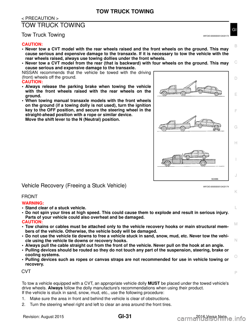
• Never tow a CVT model with the rear wheels raised and the front wheels on the ground. This may
cause serious and expensive damage to the transaxle. If it is necessary to tow the vehicle with the
rear wheels raised, always use towin g dollies under the front wheels.
• Never tow a CVT model from the rear (that is b ackward) with four wheels on the ground. This may
cause serious and expensive damage to the transaxle.
NISSAN recommends that the vehicle be towed with the driving
(front) wheels off the ground.
CAUTION:
• Always release the parking br ake when towing the vehicle
with the front wheels raised with the rear wheels on the
ground.
• When towing manual transaxle models with the front wheels on the ground (if a towing dolly is not used), turn the ignition
key to the OFF position, and secu re the steering wheel in the
straight-ahead position with a rope or similar device.
Move the shift lever to th e N (Neutral) position.
Vehicle Recovery (Freeing a Stuck Vehicle)INFOID:0000000012433174
FRONT
WARNING:
• Stand clear of a stuck vehicle.
• Do not spin your tires at high speed. This could cause them to explode and result in serious injury.
Parts of your vehicle could also overheat and be damaged.
CAUTION:
• Tow chains or cables must be attached only to the vehicle recovery hooks or main structural mem-
bers of the vehicle. Otherwise, the vehicle body will be damaged.
• Do not use the vehicle tie downs to free a vehicle stuck in sand, snow, mud, etc. Never tow the vehi-
cle using the vehicle tie downs or recovery hooks.
• Always pull the cable straight out from the front of the vehicle. Never pull on the hook at an angle.
• Pulling devices should be routed so they do not touch any part of the suspension, steering, brake or
cooling systems.
• Pulling devices such as ropes or canvas straps ar e not recommended for use in vehicle towing or
recovery.
CVT
To tow a vehicle equipped with a CVT, an appropriate vehicle dolly MUST be placed under the towed vehicle's
drive wheels. Always follow the dolly manufacture's re commendations when using their product.
If the vehicle is stuck in sand, snow , mud, etc., use the following procedure:
1. Make sure the area in front and behind the vehicle is clear of obstructions.
2. Turn the steering wheel right and left to clear an area around the front tires.
SGI986
Revision: August 2015 2016 Versa Note
cardiagn.com
Page 1934 of 3641

GI-46
< BASIC INSPECTION >
SERVICE INFORMATION FOR ELECTRICAL INCIDENT
Resistance Check Method
• Disconnect the battery negative cable and remove the blown fuse.
• Disconnect all loads (SW1 open, relay disconnected and solenoid disconnected) powered through the fuse.
• Connect one probe of the DMM to the load side of the fuse terminal. Connect the other probe to a knowngood ground.
• With SW1 open, check for continuity. continuity; short is between fuse terminal and SW1 (point A).
no continuity; short is further down the circuit than SW1.
• Close SW1 and disconnect the relay. Put probes at the load side of fuse terminal and a known good ground. Then, check for continuity.
continuity; short is between SW1 and the relay (point B).
no continuity; short is further down the circuit than the relay.
• Close SW1 and jump the relay contacts with jumper wire. Put probes at the load side of fuse terminal and a known good ground. Then, check for continuity.
continuity; short is between relay and solenoid (point C).
no continuity; check solenoid, retrace steps.
Voltage Check Method
• Remove the blown fuse and disconnect all loads (i.e. SW1 open, relay disconnected and solenoid discon-
nected) powered through the fuse.
• Turn the ignition key to the ON or START position. Verify battery voltage at the battery + side of the fuse ter- minal (one lead on the battery + terminal side of the fuse block and one lead on a known good ground).
• With SW1 open and the DMM leads across both fuse terminals, check for voltage. voltage; short is between fuse block and SW1 (point A).
no voltage; short is further down the circuit than SW1.
• With SW1 closed, relay and solenoid disconnected and the DMM leads across both fuse terminals, check for voltage.
voltage; short is between SW1 and the relay (point B).
no voltage; short is further down the circuit than the relay.
• With SW1 closed, relay contacts jumped with fused jumper wire check for voltage. voltage; short is down the circuit of the relay or between the relay and the disconnected solenoid (point C).
no voltage; retrace steps and check power to fuse block.
GROUND INSPECTION
• Ground connections are very important to the proper operation of electrical and electronic circuits. Ground
connections are often exposed to moisture, dirt and other corrosive elements. The corrosion (rust) can
become an unwanted resistance. This unwanted resistance can change the way a circuit works.
• Electronically controlled circuits are very sens itive to proper grounding. A loose or corroded ground can
drastically affect an electronically controlled circuit. A poor or corroded ground can easily affect the circuit.
Even when the ground connection looks clean, there c an be a thin film of rust on the surface.
• When inspecting a ground connection follow these rules:
- Remove the ground bolt or screw.
- Inspect all mating surfaces for tarnish, dirt, rust, etc.
- Clean as required to assure good contact.
- Reinstall bolt or screw securely.
- Inspect for “add-on” accessories which may be interfering with the ground circuit.
- If several wires are crimped into one ground eyelet terminal, check for proper crimps. Make sure all of the
wires are clean, securely fastened and providing a good ground path. If multiple wires are cased in one eye-
let make sure no ground wires have excess wire insulation.
Revision: August 2015 2016 Versa Note
cardiagn.com
Page 1938 of 3641
GI-50
< BASIC INSPECTION >
CONSULT/GST CHECKING SYSTEM
CONSULT/GST CHECKING SYSTEM
DescriptionINFOID:0000000012433188
NOTE:
This vehicle is diagnosed using the CONSULT-III plus.
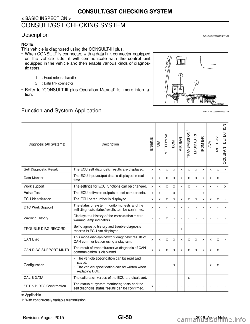
• When CONSULT is connected with a data link connector equippedon the vehicle side, it will communicate with the control unit
equipped in the vehicle and then enable various kinds of diagnos-
tic tests.
• Refer to “CONSULT-III plus Operation Manual” for more informa- tion.
Function and System ApplicationINFOID:0000000012433189
x: Applicable
1: With continuously variable transmission 1 : Hood release handle
2 : Data link connector
ALAIA0095ZZ
Diagnosis (All Systems)
Description
ENGINE
ABS
METER/M&A BCM
AIR BAG
TRANSMISSION
1
EPS/DAST 3 IPDM E/R AV M
MULTI AV
OCCUPANT DETECTION
Self Diagnostic Result The ECU self diagnostic results are displayed. x x x x x x x x x x -
Data Monitor The ECU input/output data is displayed in real
time. xxxxxxxxxx -
Work support The settings for ECU functions can be changed. x x x x - x - - x - x
Active Test The ECU activates outputs to test components. x x - x - - - x - - -
ECU identification The ECU part number is displayed. xxxxxxxxxx -
DTC Work Support The status of system monitoring tests and the
self diagnosis status/results can be confirmed. x----------
Warning History Displays the history of the combination meter
warning lamp indicators.
--x--------
TROUBLE DIAG RECORD Self diagnostic history and trouble diagnosis
records in ECU are displayed. ----x------
CAN Diag This mode displays network diagnostic results of
CAN communication using a diagram. xxxxxxxxxx -
CAN DIAG SUPPORT MNTR The result of transmit/receive diagnosis of CAN
communication is displayed.
xxxxxxxxxx -
Configuration • The vehicle specification can be read and
saved.
• The vehicle specification can be written when
replacing ECU. ---x----xx-
CALIB DATA The calibration values of the ECU are displayed. - - - - - x - - - - -
SRT & P-DTC Confirmation The status of system monitoring tests and the
self diagnosis status/results can be confirmed. x----------
Revision: August 2015
2016 Versa Note
cardiagn.com