Page 1674 of 3641

EXL-22
< SYSTEM DESCRIPTION >
DIAGNOSIS SYSTEM (IPDM E/R)
ECU IDENTIFICATION
The IPDM E/R part number is displayed.
SELF DIAGNOSTIC RESULT
Refer to PCS-20, "DTCIndex".
DATA MONITOR
ACTIVE TEST
Data Monitor The IPDM E/R input/output data is displayed in real time.
Active Test The IPDM E/R activates outputs to test components.
CAN Diag Support Mntr The result of transmit/receive diagnosis of CAN communication is displayed.
Direct Diagnostic Mode
Description
Monitor Item [Unit]Main
Signals Description
MOTOR FAN REQ [1/2/3/4] ×Indicates cooling fan speed signal received from ECM on CAN communication
line
AC COMP REQ [On/Off] ×Indicates A/C compressor request signal received from ECM on CAN commu-
nication line
TAIL&CLR REQ [On/Off] ×Indicates position light request signal received from BCM on CAN communica-
tion line
HL LO REQ [On/Off] ×Indicates low beam request signal received from BCM on CAN communication
line
HL HI REQ [On/Off] ×Indicates high beam request signal received from BCM on CAN communication
line
FR FOG REQ [On/Off] ×Indicates front fog light request signal received from BCM on CAN communica-
tion line
FR WIP REQ [Stop/1LOW/Low/Hi] ×Indicates front wiper request signal received from BCM on CAN communication
line
WIP AUTO STOP [STOP P/ACT P] ×Indicates condition of front wiper auto stop signal
WIP PROT [Off/BLOCK] ×Indicates condition of front wiper fail-safe operation
IGN RLY1 -REQ [On/Off] Indicates ignition switch ON signal received from BCM on CAN communication
line
IGN RLY [On/Off] ×Indicates condition of ignition relay
PUSH SW [On/Off] Indicates condition of push-button ignition switch
INTER/NP SW [On/Off] Indicates condition of CVT shift position
ST RLY CONT [On/Off] Indicates starter relay status signal received from BCM on CAN communication
line
IHBT RLY -REQ [On/Off] Indicates starter control relay signal received from BCM on CAN communication
line
ST/INHI RLY [Off/ ST /INHI] Indicates condition of starter relay and starter control relay
DETENT SW [On/Off] Indicates condition of CVT shift selector (park position switch)
DTRL REQ [Off] Indicates daytime running light request signal received from BCM on CAN com-
munication line
THFT HRN REQ [On/Off] Indicates theft warning horn request signal received from BCM on CAN commu-
nication line
HORN CHIRP [On/Off] Indicates horn reminder signal received from BCM on CAN communication line
Te s t i t e m D e s c r i p t i o n
HORN This test is able to check horn operation [On].
FRONT WIPER This test is able to check wiper motor operation [Hi/Lo/Off].
Revision: August 2015 2016 Versa Note
cardiagn.com
Page 1676 of 3641
EXL-24
< ECU DIAGNOSIS INFORMATION >
BCM, IPDM E/R
ECU DIAGNOSIS INFORMATION
BCM, IPDM E/R
List of ECU ReferenceINFOID:0000000012432791
ECUReference
BCM (with Intelligent Key system) BCS-30, "
Reference Value"
BCS-48, "Fail-safe"
BCS-49, "DTCInspectionPriorityChart"
BCS-50, "DTCIndex"
BCM (without Intelligent Key system)BCS-101, "
Reference Value"
BCS-115, "Fail-safe"
BCS-115, "DTCInspectionPriorityChart"
BCS-115, "DTCIndex"
IPDM E/R
PCS-13, "
Reference Value"
PCS-19, "Fail-safe"
PCS-20, "DTCIndex"
Revision: August 2015
2016 Versa Note
cardiagn.com
Page 1755 of 3641
FRONT COMBINATION LAMPEXL-103
< REMOVAL AND INSTALLATION >
C
DE
F
G H
I
J
K
M A
B
EXL
N
O P
Removal
1. Remove plastic cover.
2. Remove bulb from the front combination lamp.
Installation
Installation is in the reverse order of removal.
CAUTION:
After installing the bulb, install the bulb socket securely for watertightness.
SIDE MARKER LAMP BULB
Removal
1. Rotate bulb socket counterclockwise and remove.
2. Remove the bulb from bulb socket.
Installation
Installation is in the reverse order of removal.
CAUTION:
After installing the bulb, install the bulb socket securely for watertightness.
FRONT TURN SIGNAL/PARKING LAMP BULB
Removal
1. Rotate bulb socket counterclockwise and remove.
2. Remove the bulb from bulb socket.
Installation
Installation is in the reverse order of removal.
CAUTION:
After installing the bulb, install the bulb socket securely for watertightness.
Revision: August 2015
2016 Versa Note
cardiagn.com
Page 1757 of 3641
FRONT FOG LAMPEXL-105
< REMOVAL AND INSTALLATION >
C
DE
F
G H
I
J
K
M A
B
EXL
N
O P
Bulb ReplacementINFOID:0000000012432837
WARNING:
Do not touch bulb by hand while it is lit or right after being turned off. Burning may result.
CAUTION:
• Do not touch the glass surface of the bulb with bare hands or allow oi l or grease to get on it to pre-
vent damage to the bulb.
• Do not leave bulb out of lamp reflector for a long time because dust, moisture smoke, etc. may affect
the performance of lamp. When replacing bulb, be sure to replace it with new one.
REMOVAL
1. Partially remove fender protector. Refer to EXT-38, "Exploded View".
2. Disconnect harness connector (1) from front fog lamp bulb.
3. Rotate the bulb (2) counterclockwise and remove.
INSTALLATION
Installation is in the reverse order of removal.
CAUTION:
After installing the bulb, install the bulb socket securely for watertightness.
SKIB8304J
Revision: August 2015 2016 Versa Note
cardiagn.com
Page 1762 of 3641

EXL-110
< REMOVAL AND INSTALLATION >
REAR COMBINATION LAMP
2. Rotate stop/tail lamp bulb socket counterclockwise and remove.
3. Remove stop/tail lamp bulb from bulb socket.
Installation
Installation is in the reverse order of removal.
CAUTION:
After installing the bulb, install bulb socket securely for watertightness.
REAR TURN SIGNAL LAMP BULB
Removal
1. Remove rear combination lamp. Refer to EXL-109, "Removal and Installation".
2. Rotate rear turn signal lamp bulb socket counterclockwise and remove.
3. Remove rear turn signal lamp bulb from bulb socket.
Installation
Installation is in the reverse order of removal.
CAUTION:
After installing the bulb, install bu lb socket securely for watertightness.
BACK-UP LAMP BULB
Removal
1. Remove rear combination lamp. Refer to EXL-109, "Removal and Installation".
2. Rotate back-up lamp bulb socket counterclockwise and remove.
3. Remove back-up lamp bulb from bulb socket.
Installation
Installation is in the reverse order of removal.
CAUTION:
After installing the bulb, install bu lb socket securely for watertightness.
Revision: August 2015 2016 Versa Note
cardiagn.com
Page 1764 of 3641

EXL-112
< REMOVAL AND INSTALLATION >
LICENSE PLATE LAMP
LICENSE PLATE LAMP
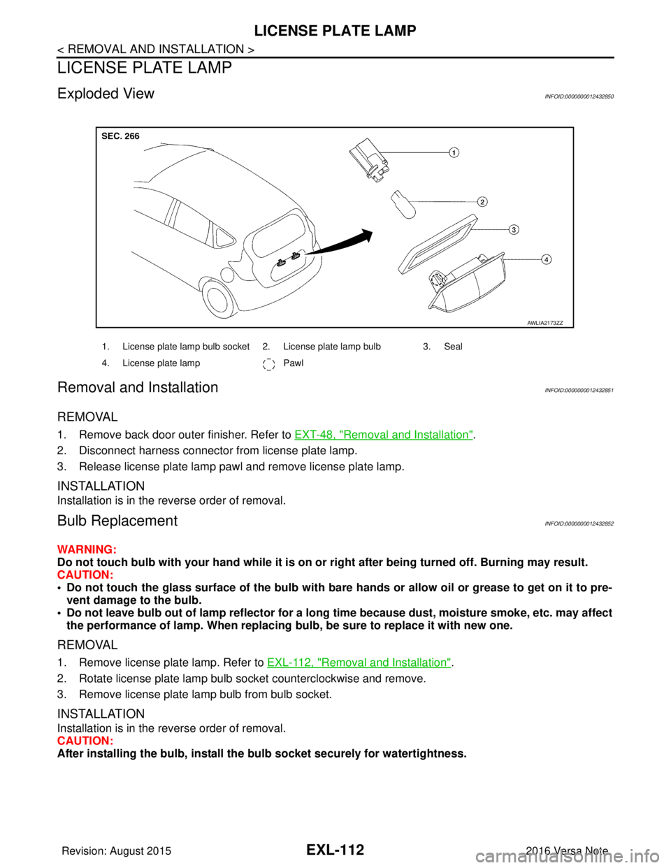
Exploded ViewINFOID:0000000012432850
Removal and InstallationINFOID:0000000012432851
REMOVAL
1. Remove back door outer finisher. Refer to EXT-48, "Removal and Installation".
2. Disconnect harness connector from license plate lamp.
3. Release license plate lamp pawl and remove license plate lamp.
INSTALLATION
Installation is in the reverse order of removal.
Bulb ReplacementINFOID:0000000012432852
WARNING:
Do not touch bulb with your hand while it is on or right after being turned off. Burning may result.
CAUTION:
• Do not touch the glass surface of the bulb with bare hands or allow oil or grease to get on it to pre- vent damage to the bulb.
• Do not leave bulb out of lamp reflector for a long time because dust, moisture smoke, etc. may affect
the performance of lamp. When replacing bulb, be sure to replace it with new one.
REMOVAL
1. Remove license plate lamp. Refer to EXL-112, "Removal and Installation".
2. Rotate license plate lamp bulb socket counterclockwise and remove.
3. Remove license plate lamp bulb from bulb socket.
INSTALLATION
Installation is in the reverse order of removal.
CAUTION:
After installing the bulb, install the bulb socket securely for watertightness.
1. License plate lamp bulb socket 2. License plate lamp bulb 3. Seal
4. License plate lamp Pawl
AWLIA2173ZZ
Revision: August 2015 2016 Versa Note
cardiagn.com
Page 1765 of 3641

FRONT COMBINATION LAMPEXL-113
< UNIT DISASSEMBLY AND ASSEMBLY >
C
DE
F
G H
I
J
K
M A
B
EXL
N
O P
UNIT DISASSEMBLY AND ASSEMBLY
FRONT COMBINATION LAMP
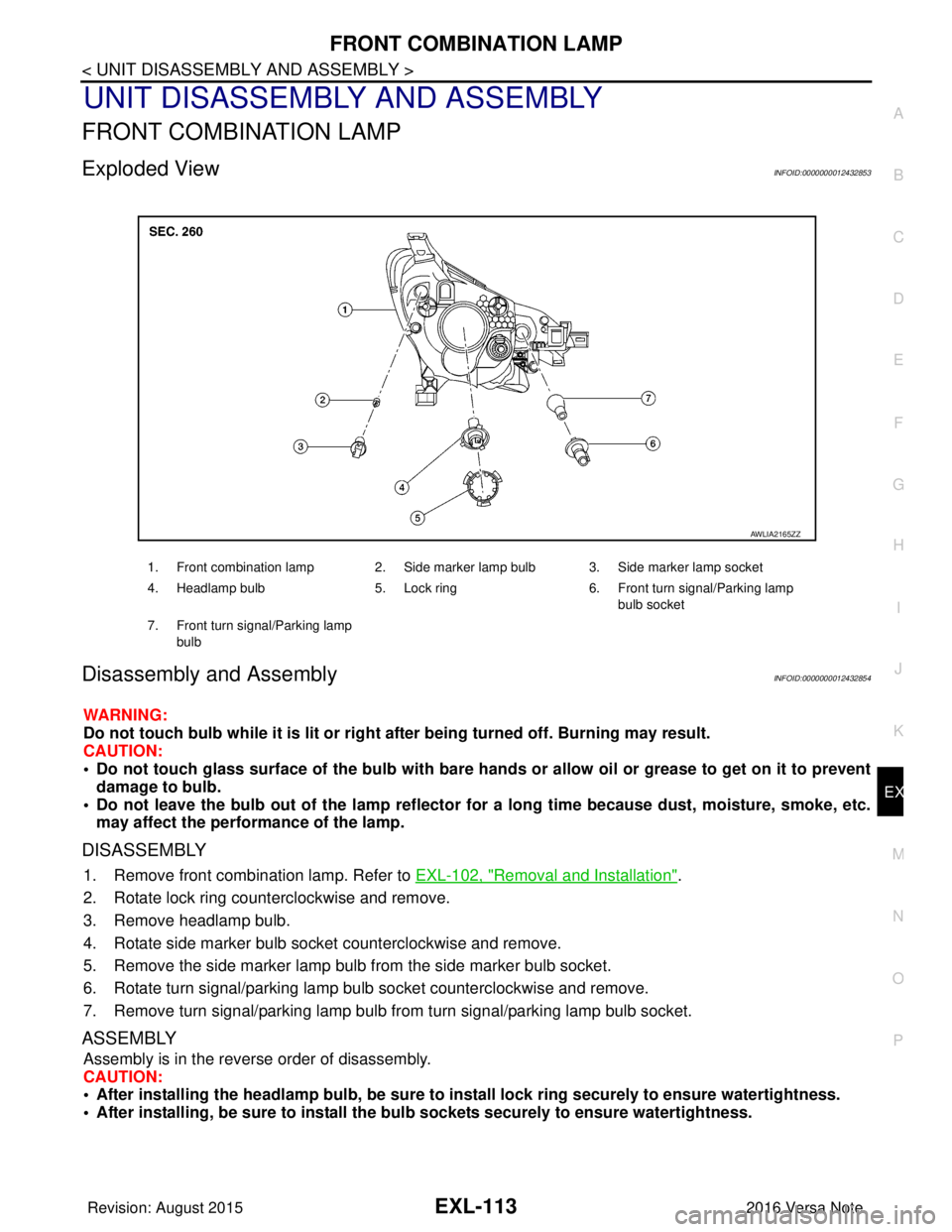
Exploded ViewINFOID:0000000012432853
Disassembly and AssemblyINFOID:0000000012432854
WARNING:
Do not touch bulb while it is lit or right after being turned off. Burning may result.
CAUTION:
• Do not touch glass surface of the bulb with bare hands or allow oil or grease to get on it to prevent damage to bulb.
• Do not leave the bulb out of the lamp reflector for a long time because dust , moisture, smoke, etc.
may affect the performance of the lamp.
DISASSEMBLY
1. Remove front combination lamp. Refer to EXL-102, "Removal and Installation".
2. Rotate lock ring counterclockwise and remove.
3. Remove headlamp bulb.
4. Rotate side marker bulb socket counterclockwise and remove.
5. Remove the side marker lamp bulb from the side marker bulb socket.
6. Rotate turn signal/parking lamp bulb socket counterclockwise and remove.
7. Remove turn signal/parking lamp bulb from turn signal/parking lamp bulb socket.
ASSEMBLY
Assembly is in the reverse order of disassembly.
CAUTION:
• After installing the headlamp bulb, be sure to install lock ring securely to ensure watertightness.
• After installing, be sure to install the bulb sockets securely to ensure watertightness.
1. Front combination lamp 2. Side marker lamp bulb 3. Side marker lamp socket
4. Headlamp bulb 5. Lock ring 6. Front turn signal/Parking lamp
bulb socket
7. Front turn signal/Parking lamp bulb
AWLIA2165ZZ
Revision: August 2015 2016 Versa Note
cardiagn.com
Page 1766 of 3641

EXL-114
< UNIT DISASSEMBLY AND ASSEMBLY >
REAR COMBINATION LAMP
REAR COMBINATION LAMP
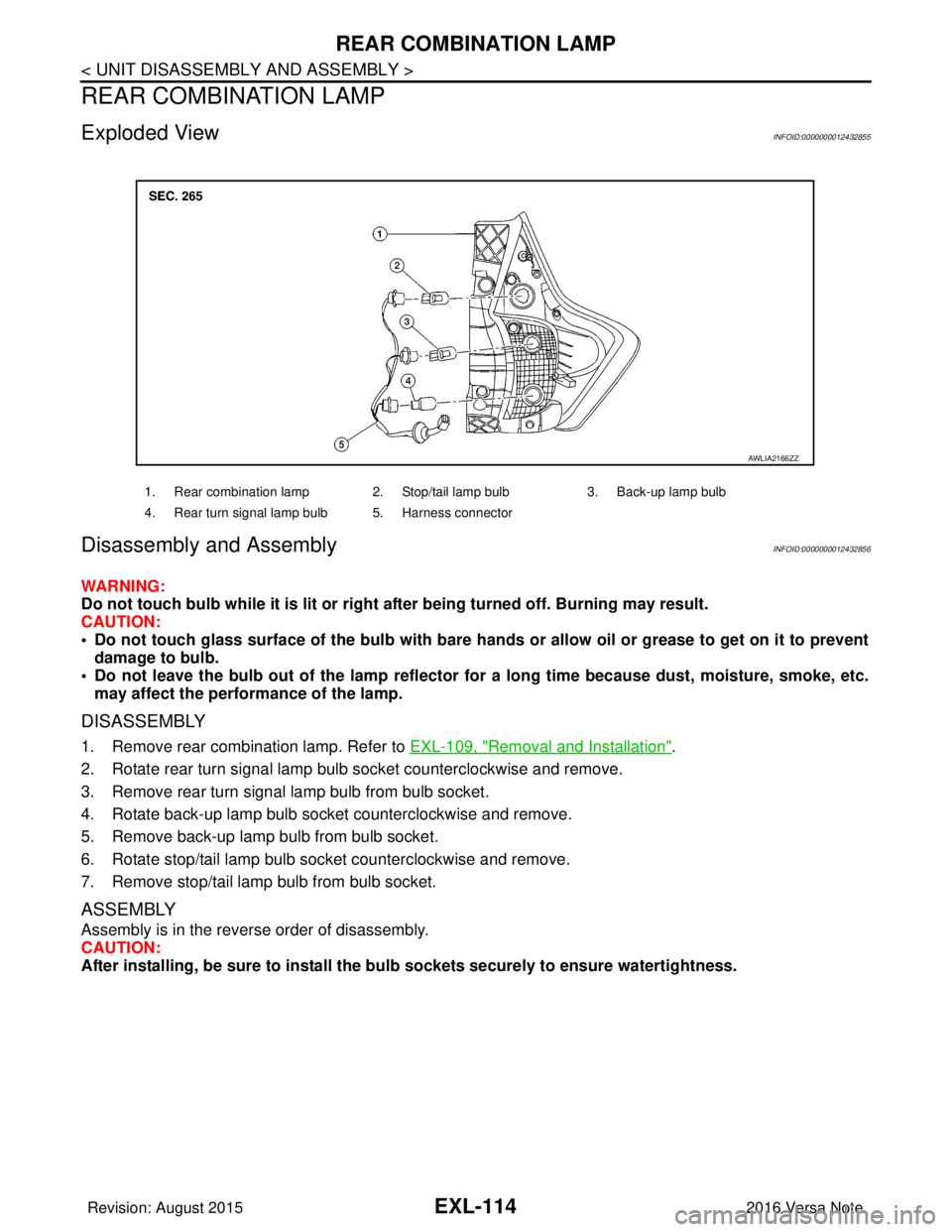
Exploded ViewINFOID:0000000012432855
Disassembly and Assembly INFOID:0000000012432856
WARNING:
Do not touch bulb while it is lit or right after being turned off. Burning may result.
CAUTION:
• Do not touch glass surface of the bulb with bare hands or allow oil or grease to get on it to preventdamage to bulb.
• Do not leave the bulb out of the lamp reflector fo r a long time because dust, moisture, smoke, etc.
may affect the performance of the lamp.
DISASSEMBLY
1. Remove rear combination lamp. Refer to EXL-109, "Removal and Installation".
2. Rotate rear turn signal lamp bulb socket counterclockwise and remove.
3. Remove rear turn signal lamp bulb from bulb socket.
4. Rotate back-up lamp bulb socket counterclockwise and remove.
5. Remove back-up lamp bulb from bulb socket.
6. Rotate stop/tail lamp bulb socket counterclockwise and remove.
7. Remove stop/tail lamp bulb from bulb socket.
ASSEMBLY
Assembly is in the reverse order of disassembly.
CAUTION:
After installing, be sure to install the bu lb sockets securely to ensure watertightness.
1. Rear combination lamp 2. Stop/tail lamp bulb 3. Back-up lamp bulb
4. Rear turn signal lamp bulb 5. Harness connector
AWLIA2166ZZ
Revision: August 2015 2016 Versa Note
cardiagn.com