2016 NISSAN NOTE seat adjustment
[x] Cancel search: seat adjustmentPage 1002 of 3641

EM-1
ENGINE
C
DE
F
G H
I
J
K L
M
SECTION EM
A
EM
N
O P
CONTENTS
ENGINE MECHANICAL
HR16DE
PRECAUTION ....... ........................................
3
PRECAUTIONS .............................................. .....3
Precaution for Supplemental Restraint System
(SRS) "AIR BAG" and "SEAT BELT PRE-TEN-
SIONER" ............................................................. ......
3
Precaution for Procedure without Cowl Top Cover ......3
Draining Engine Coolant ...........................................3
Disconnecting Fuel Piping .........................................3
Removal and Disassembly ........................................3
Inspection, Repair and Replacement ........................4
Assembly and Installation .........................................4
Parts Requiring Angle Tightening ....................... ......4
Precaution for Liquid Gasket .....................................4
PREPARATION ............................................6
PREPARATION .............................................. .....6
Special Service Tools .......................................... ......6
Commercial Service Tools ........................................7
BASIC INSPECTION ...................................10
CAMSHAFT VALVE CLEARANCE ............... ....10
Inspection and Adjustment .................................. ....10
COMPRESSION PRESSURE ............................13
Inspection ............................................................ ....13
SYMPTOM DIAGNOSIS ..............................14
NOISE, VIBRATION AND HARSHNESS
(NVH) TROUBLESHOOTING ........................ ....
14
NVH troubleshooting Chart ................................. ....14
PERIODIC MAINTENANCE .........................16
DRIVE BELT ................................................... ....16
Exploded View .................................................... ....16
Removal and Installation .........................................16
Inspection ............................................................ ....17
Adjustment ...............................................................17
AIR CLEANER FILTER .....................................19
Exploded View .........................................................19
Removal and Installation .........................................19
SPARK PLUG ...................................................21
Exploded View .........................................................21
Removal and Installation .........................................21
REMOVAL AND INSTALLATION ...............24
DRIVE BELT IDLER PULLEY ..........................24
Exploded View ..................................................... ....24
Removal and Installation .........................................24
AIR CLEANER AND AIR DUCT .......................26
Exploded View .........................................................26
Removal and Installation .........................................26
INTAKE MANIFOLD .........................................28
Exploded View .........................................................28
Removal and Installation .........................................28
EXHAUST MANIFOLD ......................................31
Exploded View .........................................................31
Removal and Installation .........................................31
OIL PAN AND OIL STRAINER .........................34
Exploded View .........................................................34
Removal and Installation (Lower Oil Pan) ...............34
Removal and Installation (Upper Oil Pan) ........... ....37
FUEL INJECTOR AND FUEL TUBE ................40
Exploded View .........................................................40
Removal and Installation .........................................40
IGNITION COIL .................................................47
Exploded View .........................................................47
Removal and Installation .........................................47
ROCKER COVER .............................................48
Revision: August 2015 2016 Versa Note
cardiagn.com
Page 1017 of 3641
![NISSAN NOTE 2016 Service Repair Manual EM-16
< PERIODIC MAINTENANCE >[HR16DE]
DRIVE BELT
PERIODIC MAINTENANCE
DRIVE BELT
Exploded ViewINFOID:0000000012431693
Removal and InstallationINFOID:0000000012431694
REMOVAL
1. Remove engine undercov NISSAN NOTE 2016 Service Repair Manual EM-16
< PERIODIC MAINTENANCE >[HR16DE]
DRIVE BELT
PERIODIC MAINTENANCE
DRIVE BELT
Exploded ViewINFOID:0000000012431693
Removal and InstallationINFOID:0000000012431694
REMOVAL
1. Remove engine undercov](/manual-img/5/57363/w960_57363-1016.png)
EM-16
< PERIODIC MAINTENANCE >[HR16DE]
DRIVE BELT
PERIODIC MAINTENANCE
DRIVE BELT
Exploded ViewINFOID:0000000012431693
Removal and InstallationINFOID:0000000012431694
REMOVAL
1. Remove engine undercover. Refer to
EXT-39, "FRONT UNDER COVER : Removal and Installation".
2. Remove wheel and tire (RH) using a power tool. Refer to WT-48, "
Removal and Installation".
3. Partially remove the fender protector (RH). Refer to EXT-38, "
Removal and Installation".
4. Loosen the lock nut and then release the belt tension by turning the adjusting bolt.
5. Remove the drive belt.
INSTALLATION
1. Pull the idler pulley in the loosening direction, and then temporarily tighten the lock nut to the following
torque.
NOTE:
Do not move the lock nut from the te mporary tightened position. Go to step 2.
2. Install the drive belt on each pulley. CAUTION:
• Check that there is no engine oil, grease, or engine coolant, etc. in pulley grooves.
• Check that the belt seats securely inside the groove on each pulley.
3. Adjust drive belt tension by turning the adjusting bolt. Refer to EM-17, "
Adjustment".
CAUTION:
• Perform the belt tension adjustment with the lock nut temporarily tightened to the torque specifi-
cation listed in step 1 which preven ts the idler pulley from tilting.
• When checking immediately after in stallation, first adjust it to the specified value. Then, after
turning crankshaft two turns or more, readjust to the specified value to avoid variation in deflec-
tion between pulleys.
1. Generator 2. Water pump 3. Crankshaft pulley
4. A/C compressor 5. Tensioner idler pulley 6. Drive belt
A. Lock nut B. Adjusting bolt
ALBIA1157ZZ
Lock nut
(Temporary tightening): 4.4 N·m (0.45 kg-m, 39 in-lb)
Revision: August 2015
2016 Versa Note
cardiagn.com
Page 1018 of 3641
![NISSAN NOTE 2016 Service Repair Manual DRIVE BELTEM-17
< PERIODIC MAINTENANCE > [HR16DE]
C
D
E
F
G H
I
J
K L
M A
EM
NP
O
4. Tighten the lock nut to final tightening specification.
5. Check that belt tension is within the specification usin NISSAN NOTE 2016 Service Repair Manual DRIVE BELTEM-17
< PERIODIC MAINTENANCE > [HR16DE]
C
D
E
F
G H
I
J
K L
M A
EM
NP
O
4. Tighten the lock nut to final tightening specification.
5. Check that belt tension is within the specification usin](/manual-img/5/57363/w960_57363-1017.png)
DRIVE BELTEM-17
< PERIODIC MAINTENANCE > [HR16DE]
C
D
E
F
G H
I
J
K L
M A
EM
NP
O
4. Tighten the lock nut to final tightening specification.
5. Check that belt tension is within the specification using suitable tool. Refer to
EM-116, "
Drive Belt".
InspectionINFOID:0000000012431695
• Inspection should be done only when engine is cold or over 30
minutes after the engine is stopped.
• Visually check belt for wear, damage, and cracks on inside and edges.
• Turn crankshaft pulley clockwise twice, and check that the tension on all pulleys equalizes before testing.
• When measuring deflection, apply 98.1 N (10 kg, 22 lb) at the ( ) marked point.
• Measure the belt tension and frequency using suitable tool at the ( ) marked point.
CAUTION:
• When checking immediately after installation, first ad just it to the specified value. Then, after turning
crankshaft two turns or more, readjust to the specified value to avoid varia tion in deflection between
pulleys.
AdjustmentINFOID:0000000012431696
CAUTION:
• When belt is replaced with new one, adjust belt te nsion to the value for “New belt,” because new belt
will not fully seat in the pulley groove.
• When tension of the belt being used exceeds “Limit,” adjust it to the value for “After adjusted.”
• When installing a belt, check it is correctly engaged with the pulley groove.
• Do not allow engine oil or engine coolant to get on the belt.
• Do not twist or bend the belt strongly.
1. Partially remove the fender protector (RH) front side clip. Refer to EXT-38, "
Removal and Installation".
2. Loosen lock nut (A) and temporarily set to the following torque.
3. Adjust the belt tension by turning the adjusting bolt. Refer to EM-116, "
Drive Belt".
CAUTION: Lock nut (Final tightening) :
34.8 N·m (3.5 kg-m, 26 ft-lb)
(1) : Generator
(2) : Water pump
(3) : Crankshaft pulley
(4) : A/C compressor
(5) : Idler pulley
(6) : Drive belt
Belt deflection/belt tension and frequency : Refer to EM-116, "Drive Belt".
PBIC3642E
LocationLocation of adjuster and tightening method
Drive belt Adjusting bolt on idler pulley
Lock nut (A)
(Temporary tightening): 4.4 N·m (0.45 kg-m, 39 in-lb)
(1) : Generator
(2) : Water pump
(3) : Crankshaft pulley
(4) : A/C compressor
(5) : Idler pulley
(6) : Drive belt
(B) : Adjusting bolt
PBIC3643E
Revision: August 2015
2016 Versa Note
cardiagn.com
Page 1090 of 3641
![NISSAN NOTE 2016 Service Repair Manual ENGINE ASSEMBLYEM-89
< UNIT REMOVAL AND INSTALLATION > [HR16DE]
C
D
E
F
G H
I
J
K L
M A
EM
NP
O
17. Use a suitable jack (A) to securely support the bottom of the
engine and the transaxle assembly.
CAU NISSAN NOTE 2016 Service Repair Manual ENGINE ASSEMBLYEM-89
< UNIT REMOVAL AND INSTALLATION > [HR16DE]
C
D
E
F
G H
I
J
K L
M A
EM
NP
O
17. Use a suitable jack (A) to securely support the bottom of the
engine and the transaxle assembly.
CAU](/manual-img/5/57363/w960_57363-1089.png)
ENGINE ASSEMBLYEM-89
< UNIT REMOVAL AND INSTALLATION > [HR16DE]
C
D
E
F
G H
I
J
K L
M A
EM
NP
O
17. Use a suitable jack (A) to securely support the bottom of the
engine and the transaxle assembly.
CAUTION:
Put a piece of wood or an equivalent as the supporting sur-
face and secure in a stable condition.
18. Remove engine mounting insulator (RH) (1).
19. Remove engine through bolt-securing nut (C).
20. Carefully lower suitable jack, or raise lift to remove the engine and the transaxle assembly. Observe the following cautions:
CAUTION:
• Check that no part interferes with the vehicle side.
• Before and during lifting, always check if any harnesses are left connected.
• During removal, always be careful to prevent the vehic le from falling off the lift due to changes in
the center of gravity.
• If necessary, support the vehicle by setting jack or suitable tool at the rear.
21. Remove starter motor. Refer to STR-31, "
Exploded View".
22. Lift with a hoist and separate the engine from the transaxle assembly. Refer to TM-24, "
Exploded View"
(M/T models) and TM-259, "Exploded View" (CVT models).
INSTALLATION
Installation is in the reverse order of removal.
CAUTION:
• Do not allow engine oil to get on engine mounting insulator. Be careful not to damage engine mount-
ing insulator.
• Check that each mounting insulator is seated properly, and tighten nuts and bolts.
• When installation directions are specified, instal l parts according to the direction marks on them,
referring to the figure of components. Refer to EM-86, "
Exploded View".
• Inspect vehicle alignment and adjust (If necessary). Refer to FSU-8, "
Adjustment".
Engine Mounting Insulator (RH)
• Tighten bolts include spec table showing installation torque for
engine mounting bracket in the numerical order as shown.
INSPECTION AFTER INSTALLATION
PBIC3223J
(2) : Engine mounting insulator (LH)
(A) : Engine front side
(B) : Transaxle side
JSBIA1223ZZ
: Front
JPBIA2809ZZ
Revision: August 2015 2016 Versa Note
cardiagn.com
Page 1749 of 3641

HEADLAMP AIMING ADJUSTMENTEXL-97
< PERIODIC MAINTENANCE >
C
DE
F
G H
I
J
K
M A
B
EXL
N
O P
PERIODIC MAINTENANCE
HEADLAMP AIMING ADJUSTMENT
InspectionINFOID:0000000012432828
PREPARATION BEFORE ADJUSTING
Before performing aiming adjustment, check the following:
• Ensure all tires are inflated to correct pressure.
• Place vehicle and screen on level surface.
• Ensure there is no load in vehicle other than the driver (or equivalent weight placed in driver's position).
• Coolant and engine oil filled to correct level, and fuel tank full.
• Remove cargo and/or luggage to maintain an unloaded vehicle condition.
• Confirm spare tire, jack and tools are properly stowed.
• Carefully wipe off any dirt from headlamp lens. CAUTION:
Do not use organic solvent (thinner, gasoline etc.)
• Place a driver or equivalent weight of 68.5 kg (150 lb) on the driver seat.
• By hand, bounce the front and rear of the vehicle to settle the suspension and eliminate any static load.
• Place the front tires in the straight ahead position.
• Confirm headlamp aiming switch is set to "0" (zero) position.
• Aim each headlamp individually and ensure other headlamp beam pattern is blocked from screen.
NOTE:
• For headlamp aiming details, refer to regulations in your area.
• By regulation, no means for horizontal aim adjustment is provided from the factory; only vertical aim is
adjustable.
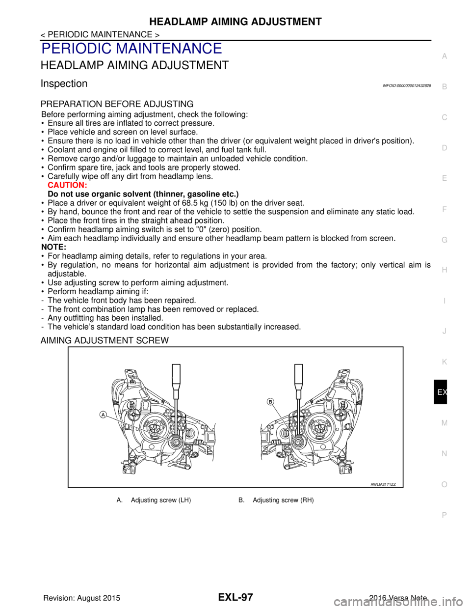
• Use adjusting screw to perform aiming adjustment.
• Perform headlamp aiming if:
- The vehicle front body has been repaired.
- The front combination lamp has been removed or replaced.
- Any outfitting has been installed.
- The vehicle’s standard load condition has been substantially increased.
AIMING ADJUSTMENT SCREW
AWLIA2171ZZ
A. Adjusting screw (LH) B. Adjusting screw (RH)
Revision: August 2015 2016 Versa Note
cardiagn.com
Page 1752 of 3641

EXL-100
< PERIODIC MAINTENANCE >
FRONT FOG LAMP AIMING ADJUSTMENT
FRONT FOG LAMP AIMING ADJUSTMENT
InspectionINFOID:0000000012432830
PREPARATION BEFORE ADJUSTING
Before performing aiming adjustment procedure, check the following:
• Ensure all tires are inflated to correct pressure.
• Place vehicle and screen on level surface.
• Ensure there is no load in vehicle other than the driver (or equivalent weight placed in driver's position).
• Coolant and engine oil filled to correct level, and fuel tank full.
• Remove cargo and/or luggage to maintain an unloaded vehicle condition.
• Confirm spare tire, jack and tools are properly stowed.
• Carefully wipe off any dirt from fog lamp lens. CAUTION:
Do not use organic solvent (thinner, gasoline etc.)
• Place a driver or equivalent weight of 68.5 kg (150 lb) on the driver seat.
• By hand, bounce the front and rear of the vehicle to settle the suspension and eliminate any static load.
• Place the front tires in the straight ahead position.
• Aim each headlamp individually and ensure other headlamp beam pattern is blocked from screen.
NOTE:
• For headlamp aiming details, refer to regulations in your area.
• By regulation, no means for horizontal aim adjustment is provided from the factory; only vertical aim is
adjustable.
• Use adjusting screw to perform aiming adjustment.
• Perform headlamp aiming if:
- The vehicle front body has been repaired.
- The front combination lamp has been removed or replaced.
- Any outfitting has been installed.
- The vehicle’s standard load condition has been substantially increased.
AIMING ADJUSTMENT SCREW
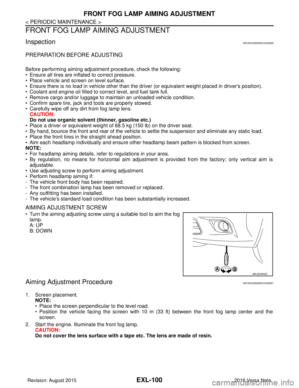
• Turn the aiming adjusting screw using a suitable tool to aim the fog
lamp.
A: UP
B: DOWN
Aiming Adjustment ProcedureINFOID:0000000012432831
1. Screen placement. NOTE:
• Place the screen perpendicular to the level road.
• Position the vehicle facing the screen with 10 m (33 ft) between the front fog lamp center and thescreen.
2. Start the engine. Illuminate the front fog lamp. CAUTION:
Do not cover the lens surface with a tape etc. The lens are made of resin.
JMLIA2040ZZ
Revision: August 2015 2016 Versa Note
cardiagn.com
Page 1787 of 3641

EXT-20
< SYMPTOM DIAGNOSIS >
SQUEAK AND RATTLE TROUBLE DIAGNOSES
1. Loose harness or harness connectors.
2. Front console map/reading lamp lens loose.
3. Loose screws at console attachment points.
SEATS
When isolating seat noise it's important to note the position the seat is in and the load placed on the seat when
the noise is present. These conditions should be duplicated when verifying and isolating the cause of the
noise.
Cause of seat noise include:
1. Headrest rods and holder
2. A squeak between the seat pad cushion and frame
3. The rear seatback lock and bracket
These noises can be isolated by moving or pressing on the suspected components while duplicating the con-
ditions under which the noise occurs. Most of thes e incidents can be repaired by repositioning the component
or applying urethane tape to the contact area.
UNDERHOOD
Some interior noise may be caused by components under the hood or on the engine wall. The noise is then
transmitted into the passenger compartment.
Causes of transmitted underhood noise include:
1. Any component installed to the engine wall
2. Components that pass through the engine wall
3. Engine wall mounts and connectors
4. Loose radiator installation pins
5. Hood bumpers out of adjustment
6. Hood striker out of adjustment
These noises can be difficult to isolate since they cannot be reached from the interior of the vehicle. The best
method is to secure, move or insulate one component at a time and test drive the vehicle. Also, engine rpm or
load can be changed to isolate the noise. Repairs can usually be made by moving, adjusting, securing, or
insulating the component causing the noise.
Revision: August 2015 2016 Versa Note
cardiagn.com
Page 1846 of 3641

FSU-1
SUSPENSION
C
DF
G H
I
J
K L
M
SECTION FSU
A
B
FSU
N
O PCONTENTS
FRONT SUSPENSION
PRECAUTION ....... ........................................2
PRECAUTIONS .............................................. .....2
Precaution for Supplemental Restraint System
(SRS) "AIR BAG" and "SEAT BELT PRE-TEN-
SIONER" ............................................................. ......
2
Precaution for Procedure without Cowl Top Cover ......2
Precaution for Suspension ........................................2
PREPARATION ............................................3
PREPARATION .............................................. .....3
Special Service Tools .......................................... ......3
Commercial Service Tools ........................................3
SYMPTOM DIAGNOSIS ...............................5
NOISE, VIBRATION AND HARSHNESS
(NVH) TROUBLESHOOTING ........................ .....
5
NVH Troubleshooting Chart ................................ ......5
PERIODIC MAINTENANCE ..........................6
FRONT SUSPENSION ASSEMBLY .............. .....6
Inspection ............................................................ ......6
WHEEL ALIGNMENT ..........................................7
Inspection ............................................................ ......7
Adjustment ................................................................8
REMOVAL AND INSTALLATION ................9
FRONT COIL SPRING AND STRUT ............. .....9
Exploded View .................................................... ......9
Removal and Installation ...........................................9
TRANSVERSE LINK .........................................10
Exploded View ..................................................... ....10
Removal and Installation .........................................10
Inspection ................................................................10
FRONT STABILIZER ........................................12
Exploded View .........................................................12
Removal and Installation .........................................12
Inspection ................................................................13
UNIT REMOVAL AND INSTALLATION ......14
FRONT SUSPENSION MEMBER .....................14
Exploded View ..................................................... ....14
Removal and Installation .........................................14
Inspection ................................................................15
UNIT DISASSEMBLY AND ASSEMBLY ....16
FRONT COIL SPRING AND STRUT ................16
Exploded View ..................................................... ....16
Disassembly and Assembly .....................................16
Inspection ................................................................19
Disposal ...................................................................19
SERVICE DATA AND SPECIFICATIONS
(SDS) ............... .......................................... ...
20
SERVICE DATA AND SPECIFICATIONS
(SDS) .................................................................
20
Wheel Alignment (Unladen*1) ..................................20
Ball Joint .............................................................. ....20
Wheelarch Height (Unladen*) ..................................21
Revision: August 2015 2016 Versa Note
cardiagn.com