2016 NISSAN NOTE seat adjustment
[x] Cancel search: seat adjustmentPage 1860 of 3641
FRONT SUSPENSION MEMBERFSU-15
< UNIT REMOVAL AND INSTALLATION >
C
DF
G H
I
J
K L
M A
B
FSU
N
O P
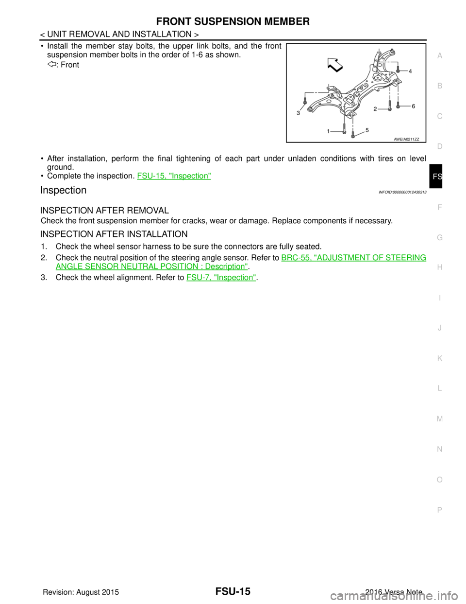
• Install the member stay bolts, the upper link bolts, and the front suspension member bolts in the order of 1-6 as shown.
: Front
• After installation, perform the final tightening of each part under unladen conditions with tires on level
ground.
• Complete the inspection. FSU-15, "
Inspection"
InspectionINFOID:0000000012430313
INSPECTION AFTER REMOVAL
Check the front suspension member for cracks, wear or damage. Replace components if necessary.
INSPECTION AFTER INSTALLATION
1. Check the wheel sensor harness to be sure the connectors are fully seated.
2. Check the neutral position of the steering angle sensor. Refer to BRC-55, "
ADJUSTMENT OF STEERING
ANGLE SENSOR NEUTRAL POSITION : Description".
3. Check the wheel alignment. Refer to FSU-7, "
Inspection".
AWEIA0211ZZ
Revision: August 2015 2016 Versa Note
cardiagn.com
Page 1864 of 3641
FRONT COIL SPRING AND STRUTFSU-19
< UNIT DISASSEMBLY AND ASSEMBLY >
C
DF
G H
I
J
K L
M A
B
FSU
N
O P
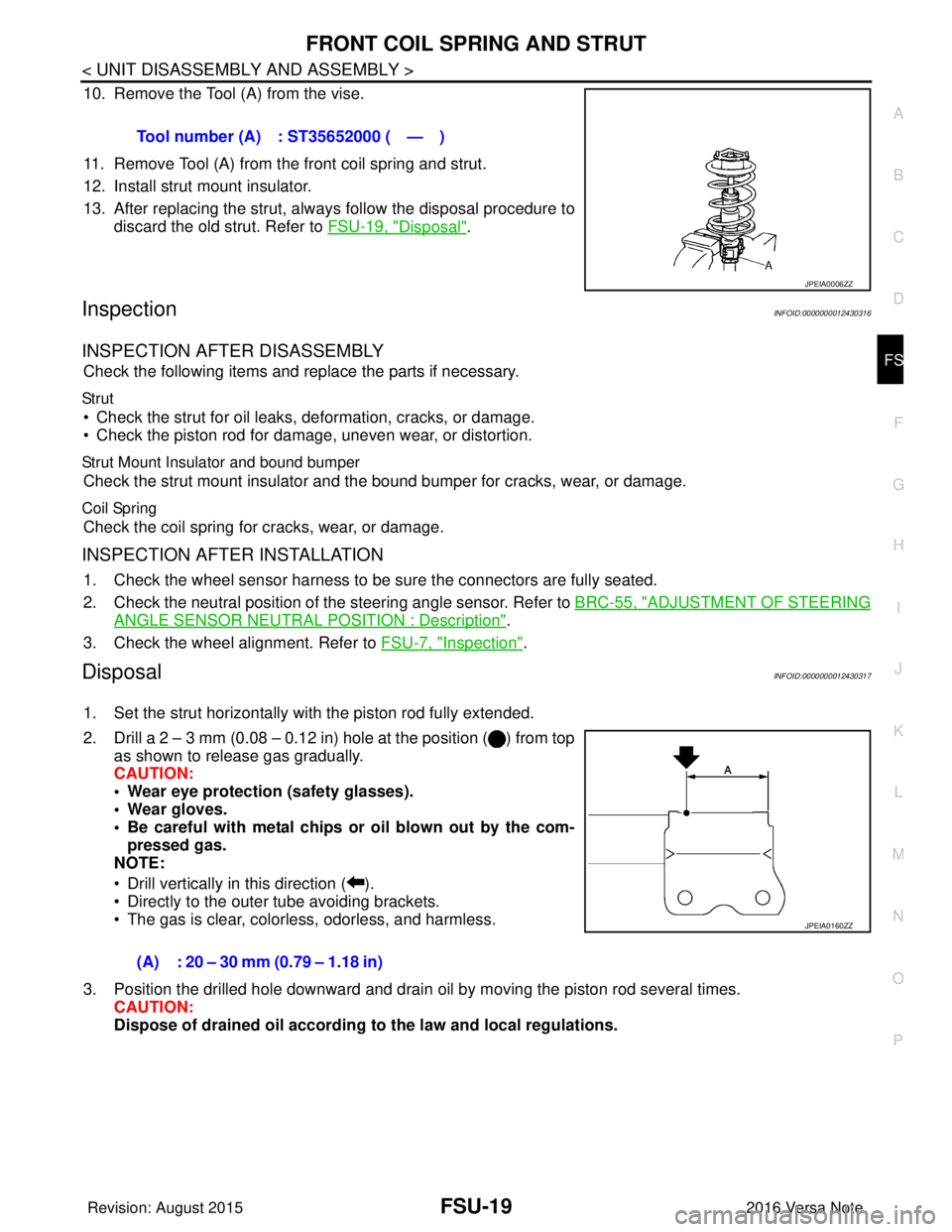
10. Remove the Tool (A) from the vise.
11. Remove Tool (A) from the front coil spring and strut.
12. Install strut mount insulator.
13. After replacing the strut, always follow the disposal procedure to discard the old strut. Refer to FSU-19, "
Disposal".
InspectionINFOID:0000000012430316
INSPECTION AFTER DISASSEMBLY
Check the following items and replace the parts if necessary.
Str ut
• Check the strut for oil leaks, deformation, cracks, or damage.
• Check the piston rod for damage, uneven wear, or distortion.
Strut Mount Insulator and bound bumper
Check the strut mount insulator and t he bound bumper for cracks, wear, or damage.
Coil Spring
Check the coil spring for cracks, wear, or damage.
INSPECTION AFTER INSTALLATION
1. Check the wheel sensor harness to be sure the connectors are fully seated.
2. Check the neutral position of the steering angle sensor. Refer to BRC-55, "
ADJUSTMENT OF STEERING
ANGLE SENSOR NEUTRAL POSITION : Description".
3. Check the wheel alignment. Refer to FSU-7, "
Inspection".
DisposalINFOID:0000000012430317
1. Set the strut horizontally with the piston rod fully extended.
2. Drill a 2 – 3 mm (0.08 – 0.12 in) hole at the position ( ) from top
as shown to release gas gradually.
CAUTION:
• Wear eye protection (safety glasses).
• Wear gloves.
• Be careful with metal chips or oil blown out by the com-
pressed gas.
NOTE:
• Drill vertically in this direction ( ).
• Directly to the outer tube avoiding brackets.
• The gas is clear, colorless, odorless, and harmless.
3. Position the drilled hole downward and drain oil by moving the piston rod several times. CAUTION:
Dispose of drained oil according to the law and local regulations.
Tool number (A) : ST35652000 ( — )
JPEIA0006ZZ
(A) : 20 – 30 mm (0.79 – 1.18 in)
JPEIA0160ZZ
Revision: August 2015
2016 Versa Note
cardiagn.com
Page 1948 of 3641

GW-8
< SYMPTOM DIAGNOSIS >
SQUEAK AND RATTLE TROUBLE DIAGNOSES
1. Loose harness or harness connectors.
2. Front console map/reading lamp lens loose.
3. Loose screws at console attachment points.
SEATS
When isolating seat noise it's important to note the position the seat is in and the load placed on the seat when
the noise is present. These conditions should be duplicated when verifying and isolating the cause of the
noise.
Cause of seat noise include:
1. Headrest rods and holder
2. A squeak between the seat pad cushion and frame
3. The rear seatback lock and bracket
These noises can be isolated by moving or pressing on the suspected components while duplicating the con-
ditions under which the noise occurs. Most of thes e incidents can be repaired by repositioning the component
or applying urethane tape to the contact area.
UNDERHOOD
Some interior noise may be caused by components under the hood or on the engine wall. The noise is then
transmitted into the passenger compartment.
Causes of transmitted underhood noise include:
1. Any component installed to the engine wall
2. Components that pass through the engine wall
3. Engine wall mounts and connectors
4. Loose radiator installation pins
5. Hood bumpers out of adjustment
6. Hood striker out of adjustment
These noises can be difficult to isolate since they cannot be reached from the interior of the vehicle. The best
method is to secure, move or insulate one component at a time and test drive the vehicle. Also, engine rpm or
load can be changed to isolate the noise. Repairs can usually be made by moving, adjusting, securing, or
insulating the component causing the noise.
Revision: August 2015 2016 Versa Note
cardiagn.com
Page 2079 of 3641
SQUEAK AND RATTLE TROUBLE DIAGNOSESIP-11
< SYMPTOM DIAGNOSIS >
C
DE
F
G H
I
K L
M A
B
IP
N
O P
1. Loose harness or harness connectors.
2. Front console map/reading lamp lens loose.
3. Loose screws at console attachment points.
SEATS
When isolating seat noise it's important to note the position the seat is in and the load placed on the seat when
the noise is present. These conditions should be duplicated when verifying and isolating the cause of the
noise.
Cause of seat noise include:
1. Headrest rods and holder
2. A squeak between the seat pad cushion and frame
3. The rear seatback lock and bracket
These noises can be isolated by moving or pressing on the suspected components while duplicating the con-
ditions under which the noise occurs. Most of thes e incidents can be repaired by repositioning the component
or applying urethane tape to the contact area.
UNDERHOOD
Some interior noise may be caused by components under the hood or on the engine wall. The noise is then
transmitted into the passenger compartment.
Causes of transmitted underhood noise include:
1. Any component installed to the engine wall
2. Components that pass through the engine wall
3. Engine wall mounts and connectors
4. Loose radiator installation pins
5. Hood bumpers out of adjustment
6. Hood striker out of adjustment
These noises can be difficult to isolate since they cannot be reached from the interior of the vehicle. The best
method is to secure, move or insulate one component at a time and test drive the vehicle. Also, engine rpm or
load can be changed to isolate the noise. Repairs can usually be made by moving, adjusting, securing, or
insulating the component causing the noise.
Revision: August 2015 2016 Versa Note
cardiagn.com
Page 2163 of 3641

INT-12
< SYMPTOM DIAGNOSIS >
SQUEAK AND RATTLE TROUBLE DIAGNOSES
1. Loose harness or harness connectors.
2. Front console map/reading lamp lens loose.
3. Loose screws at console attachment points.
SEATS
When isolating seat noise it's important to note the position the seat is in and the load placed on the seat when
the noise is present. These conditions should be duplicated when verifying and isolating the cause of the
noise.
Cause of seat noise include:
1. Headrest rods and holder
2. A squeak between the seat pad cushion and frame
3. The rear seatback lock and bracket
These noises can be isolated by moving or pressing on the suspected components while duplicating the con-
ditions under which the noise occurs. Most of thes e incidents can be repaired by repositioning the component
or applying urethane tape to the contact area.
UNDERHOOD
Some interior noise may be caused by components under the hood or on the engine wall. The noise is then
transmitted into the passenger compartment.
Causes of transmitted underhood noise include:
1. Any component installed to the engine wall
2. Components that pass through the engine wall
3. Engine wall mounts and connectors
4. Loose radiator installation pins
5. Hood bumpers out of adjustment
6. Hood striker out of adjustment
These noises can be difficult to isolate since they cannot be reached from the interior of the vehicle. The best
method is to secure, move or insulate one component at a time and test drive the vehicle. Also, engine rpm or
load can be changed to isolate the noise. Repairs can usually be made by moving, adjusting, securing, or
insulating the component causing the noise.
Revision: August 2015 2016 Versa Note
cardiagn.com
Page 2316 of 3641
MA-1
MAINTENANCE
C
DE
F
G H
I
J
K L
M B
MA
SECTION MA
N
O A
CONTENTS
MAINTENANCE
PRECAUTION .......
........................................3
PRECAUTIONS .............................................. .....3
Precaution for Supplemental Restraint System
(SRS) "AIR BAG" and "SEAT BELT PRE-TEN-
SIONER" ............................................................. ......
3
PREPARATION ............................................4
PREPARATION .............................................. .....4
Special Service Tool ........................................... ......4
Commercial Service Tool ..........................................4
PERIODIC MAINTENANCE ..........................5
GENERAL MAINTE NANCE ........................... .....5
Explanation of General Maintenance .................. ......5
PERIODIC MAINTENANCE ................................7
Introduction of Periodic Maintenance .................. ......7
RECOMMENDED FLUIDS AND LUBRI-
CANTS ................................................................
11
Fluids and Lubricants .......................................... ....11
Engine Oil Recommendation ..................................12
Anti-Freeze Coolant Mixture Ratio ..........................12
ENGINE MAINTENANCE ...................................13
DRIVE BELT .......................................................... ....13
DRIVE BELT : Exploded View ................................13
DRIVE BELT : Removal and Installation .................13
DRIVE BELT : Inspection .................................... ....14
DRIVE BELT : Adjustment ......................................14
ENGINE COOLANT ............................................... ....15
ENGINE COOLANT : Inspection .............................15
ENGINE COOLANT : Draining Engine Coolant ......16
ENGINE COOLANT : Refilling ................................16
ENGINE COOLANT : Flushing Cooling System .....18
FUEL LINES .......................................................... ....18
FUEL LINES : Inspection ........................................18
AIR CLEANER FILTER ......................................... ....18
AIR CLEANER FILTER : Exploded View ................19
AIR CLEANER FILTER : Removal and Installation
....
19
ENGINE OIL ........................................................... ....20
ENGINE OIL : Inspection .........................................20
ENGINE OIL : Draining ............................................21
ENGINE OIL : Refilling ............................................21
OIL FILTER ............................................................ ....22
OIL FILTER : Removal and Installation ...................22
SPARK PLUG ........................................................ ....22
SPARK PLUG : Exploded View ...............................23
SPARK PLUG : Removal and Installation ...............23
EVAP VAPOR LINES ............................................ ....25
EVAP VAPOR LINES : Inspection ...........................25
CHASSIS AND BODY MAINTENANCE ...........26
EXHAUST SYSTEM . ..................................................26
EXHAUST SYSTEM : Inspec tion ............................26
CVT FLUID ............................................................. ....26
CVT FLUID : Inspection ...........................................26
CVT FLUID : Replacement ......................................26
CVT FLUID : Adjustment .........................................28
CLUTCH FLUID ..................................................... ....29
CLUTCH FLUID : Inspection ...................................29
CLUTCH FLUID : Draining ......................................29
CLUTCH FLUID : Refilling .......................................30
GEAR OIL .............................................................. ....31
GEAR OIL : Inspection ............................................31
GEAR OIL : Draining ...............................................31
GEAR OIL : Refilling ................................................32
WHEELS ................................................................ ....32
WHEELS : Inspection ..............................................32
WHEELS : Adjustment ............................................32
Revision: August 2015 2016 Versa Note
cardiagn.com
Page 2328 of 3641
ENGINE MAINTENANCEMA-13
< PERIODIC MAINTENANCE >
C
DE
F
G H
I
J
K L
M B
MA
N
O A
ENGINE MAINTENANCE
DRIVE BELT
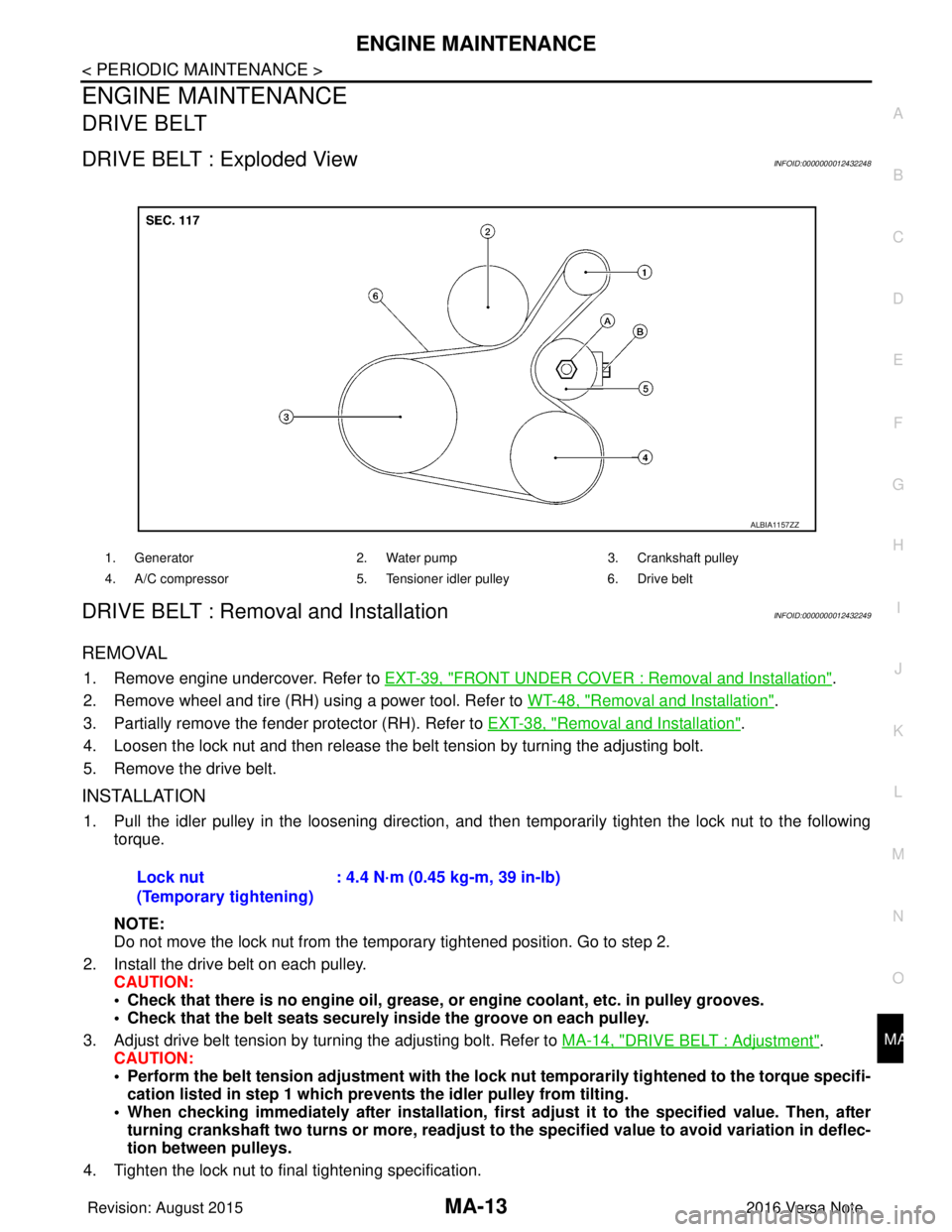
DRIVE BELT : Exploded ViewINFOID:0000000012432248
DRIVE BELT : Removal and InstallationINFOID:0000000012432249
REMOVAL
1. Remove engine undercover. Refer to
EXT-39, "FRONT UNDER COVER : Removal and Installation".
2. Remove wheel and tire (RH) using a power tool. Refer to WT-48, "
Removal and Installation".
3. Partially remove the fender protector (RH). Refer to EXT-38, "
Removal and Installation".
4. Loosen the lock nut and then release the belt tension by turning the adjusting bolt.
5. Remove the drive belt.
INSTALLATION
1. Pull the idler pulley in the loosening direction, and then temporarily tighten the lock nut to the following
torque.
NOTE:
Do not move the lock nut from the temporary tightened position. Go to step 2.
2. Install the drive belt on each pulley. CAUTION:
• Check that there is no engine oil, grease, or engine coolant, etc. in pulley grooves.
• Check that the belt seats securely inside the groove on each pulley.
3. Adjust drive belt tension by turning the adjusting bolt. Refer to MA-14, "
DRIVE BELT : Adjustment".
CAUTION:
• Perform the belt tension adjustment with the lock nut temporarily tightened to the torque specifi-
cation listed in step 1 which preven ts the idler pulley from tilting.
• When checking immediately after in stallation, first adjust it to the specified value. Then, after
turning crankshaft two turns or more, readjust to the specified value to avoid variation in deflec-
tion between pulleys.
4. Tighten the lock nut to final tightening specification.
1. Generator 2. Water pump3. Crankshaft pulley
4. A/C compressor 5. Tensioner idler pulley6. Drive belt
ALBIA1157ZZ
Lock nut
(Temporary tightening): 4.4 N·m (0.45 kg-m, 39 in-lb)
Revision: August 2015
2016 Versa Note
cardiagn.com
Page 2329 of 3641
MA-14
< PERIODIC MAINTENANCE >
ENGINE MAINTENANCE
5. Check that belt tension is within the specification using suitable tool. Refer to EM-116, "Drive Belt".
DRIVE BELT : InspectionINFOID:0000000012432250
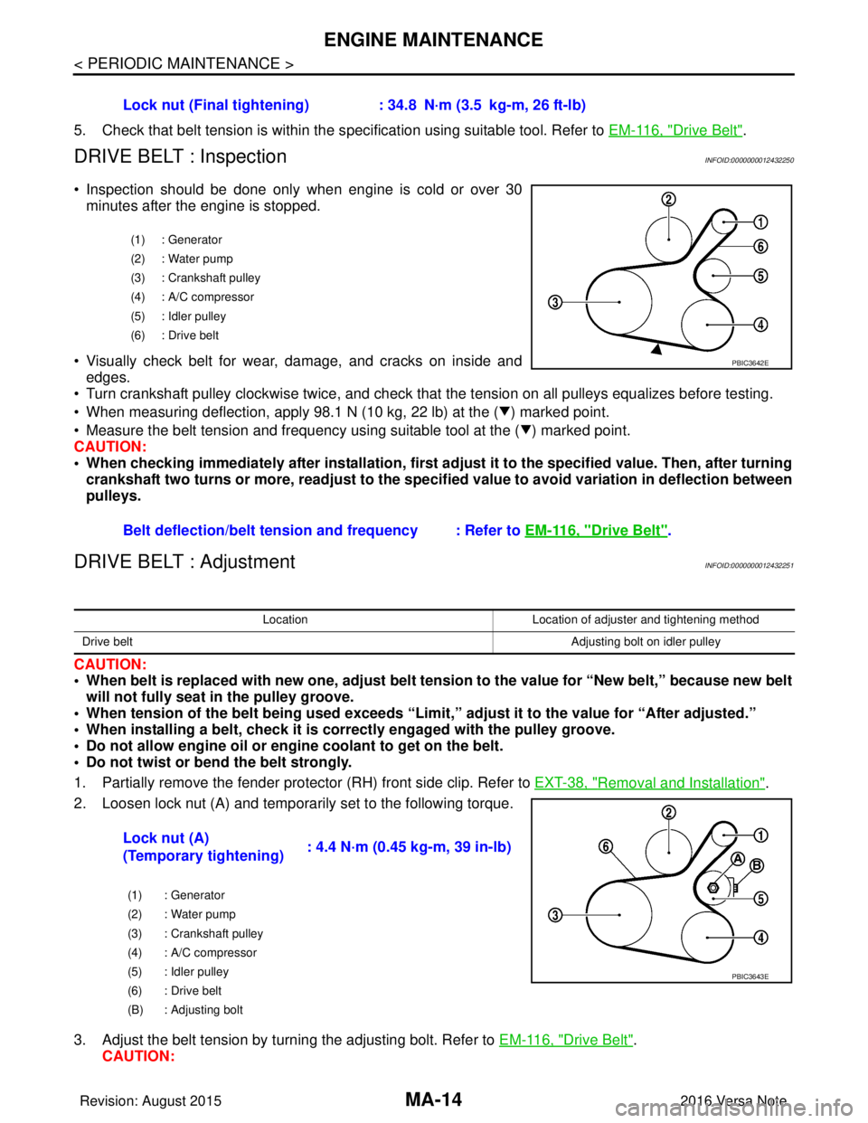
• Inspection should be done only when engine is cold or over 30
minutes after the engine is stopped.
• Visually check belt for wear, damage, and cracks on inside and edges.
• Turn crankshaft pulley clockwise twice, and check that the tension on all pulleys equalizes before testing.
• When measuring deflection, apply 98.1 N (10 kg, 22 lb) at the ( ) marked point.
• Measure the belt tension and frequency using suitable tool at the ( ) marked point.
CAUTION:
• When checking immediately after installation, first ad just it to the specified value. Then, after turning
crankshaft two turns or more, readjust to the speci fied value to avoid variation in deflection between
pulleys.
DRIVE BELT : AdjustmentINFOID:0000000012432251
CAUTION:
• When belt is replaced with new one, adjust belt tension to the value for “New belt,” because new belt will not fully seat in the pulley groove.
• When tension of the belt being used exceeds “Limit,” adjust it to the value for “After adjusted.”
• When installing a belt, check it is co rrectly engaged with the pulley groove.
• Do not allow engine oil or engine coolant to get on the belt.
• Do not twist or bend the belt strongly.
1. Partially remove the fender protector (RH) front side clip. Refer to EXT-38, "
Removal and Installation".
2. Loosen lock nut (A) and temporarily set to the following torque.
3. Adjust the belt tension by turning the adjusting bolt. Refer to EM-116, "
Drive Belt".
CAUTION: Lock nut (Final tightening) :
34.8 N·m (3.5 kg-m, 26 ft-lb)
(1) : Generator
(2) : Water pump
(3) : Crankshaft pulley
(4) : A/C compressor
(5) : Idler pulley
(6) : Drive belt
Belt deflection/belt tension and frequency : Refer to EM-116, "Drive Belt".
PBIC3642E
LocationLocation of adjuster and tightening method
Drive belt Adjusting bolt on idler pulley
Lock nut (A)
(Temporary tightening): 4.4 N·m (0.45 kg-m, 39 in-lb)
(1) : Generator
(2) : Water pump
(3) : Crankshaft pulley
(4) : A/C compressor
(5) : Idler pulley
(6) : Drive belt
(B) : Adjusting bolt
PBIC3643E
Revision: August 2015
2016 Versa Note
cardiagn.com