2016 NISSAN NOTE turn signal
[x] Cancel search: turn signalPage 574 of 3641
![NISSAN NOTE 2016 Service Repair Manual BRC-126
< DTC/CIRCUIT DIAGNOSIS >[VDC/TCS/ABS]
VDC OFF SWITCH
VDC OFF SWITCH
Component Function CheckINFOID:0000000012430906
1.CHECK VDC OFF SWITCH OPERATION
Check that VDC OFF indicator lamp in combi NISSAN NOTE 2016 Service Repair Manual BRC-126
< DTC/CIRCUIT DIAGNOSIS >[VDC/TCS/ABS]
VDC OFF SWITCH
VDC OFF SWITCH
Component Function CheckINFOID:0000000012430906
1.CHECK VDC OFF SWITCH OPERATION
Check that VDC OFF indicator lamp in combi](/manual-img/5/57363/w960_57363-573.png)
BRC-126
< DTC/CIRCUIT DIAGNOSIS >[VDC/TCS/ABS]
VDC OFF SWITCH
VDC OFF SWITCH
Component Function CheckINFOID:0000000012430906
1.CHECK VDC OFF SWITCH OPERATION
Check that VDC OFF indicator lamp in combination meter turns ON/OFF when VDC OFF switch is operated.
Is the inspection result normal?
YES >> Inspection End.
NO >> Proceed to diagnosis procedure. Refer to BRC-126, "
Diagnosis Procedure".
Diagnosis ProcedureINFOID:0000000012430907
Regarding Wiring Diagram information, refer to BRC-44, "Wiring Diagram".
1.CONNECTOR INSPECTION
1. Turn ignition switch OFF.
2. Disconnect ABS actuator and electric unit (c ontrol unit) and VDC OFF switch connectors.
3. Check connectors and terminals for deformation, disconnection, looseness or damage.
Is the inspection result normal?
YES >> GO TO 2.
NO >> Repair or replace as necessary.
2.CHECK VDC OFF SWITCH
Check VDC OFF switch. Refer to BRC-127, "
Component Inspection".
Is the inspection result normal?
YES >> GO TO 3.
NO >> Replace VDC OFF switch. Refer to BRC-146, "
Removal and Installation".
3.CHECK VDC OFF SWITCH SIGNAL
With CONSULT.
1. Connect ABS actuator and electric unit (c ontrol unit) and VDC OFF switch connectors.
2. Turn ignition switch ON.
3. In “Data Monitor” select “OFF SW” and check VDC OFF switch signal.
Is the inspection result normal?
YES >> Refer to BRC-52, "Work Flow".
NO >> GO TO 4.
4.CHECK VDC OFF SWITCH CIRCUIT
1. Turn ignition switch OFF.
2. Disconnect ABS actuator and electric unit (c ontrol unit) and VDC OFF switch connectors.
3. Check continuity between ABS actuator and electr ic unit (control unit) connector E33 terminal 20 and
VDC OFF switch connector M34 terminal 1.
4. Check continuity between ABS actuator and electric unit (control unit) connector terminal E33 terminal 20 and ground.
Condition DATA MONITOR
VDC OFF switch is pressed and released On
VDC OFF switch is pressed and released again Off
ABS actuator and electric unit (control unit) VDC OFF switch
Continuity
Connector Terminal Connector Terminal
E33 20 M34 1 Yes
Revision: August 2015 2016 Versa Note
cardiagn.com
Page 656 of 3641

COMPONENT PARTSDEF-5
< SYSTEM DESCRIPTION >
C
DE
F
G H
I
J
K
M A
B
DEF
N
O P
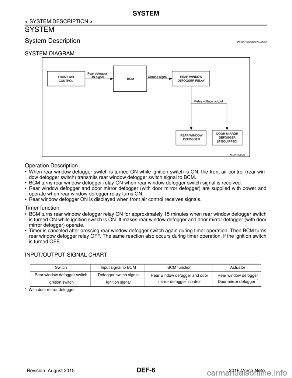
Rear window defoggerINFOID:0000000012431753
Heats the heating wire with the pow er supply from the rear window
defogger relay to prevent the rear window from fogging up.
Door mirror defoggerINFOID:0000000012431754
Heats the heating wire with the pow er supply from the rear window
defogger relay to prevent the door mirror from fogging up.
5. Rear window defogger relay Operates the rear window defogger with the control signal from BCM.
6. Condenser Removes the noise that is generated when the rear window defogger turns ON/OFF.
No.
Component Function
JMLIA2595GB
JMLIA2596GB
Revision: August 2015 2016 Versa Note
cardiagn.com
Page 657 of 3641

DEF-6
< SYSTEM DESCRIPTION >
SYSTEM
SYSTEM
System DescriptionINFOID:0000000012431755
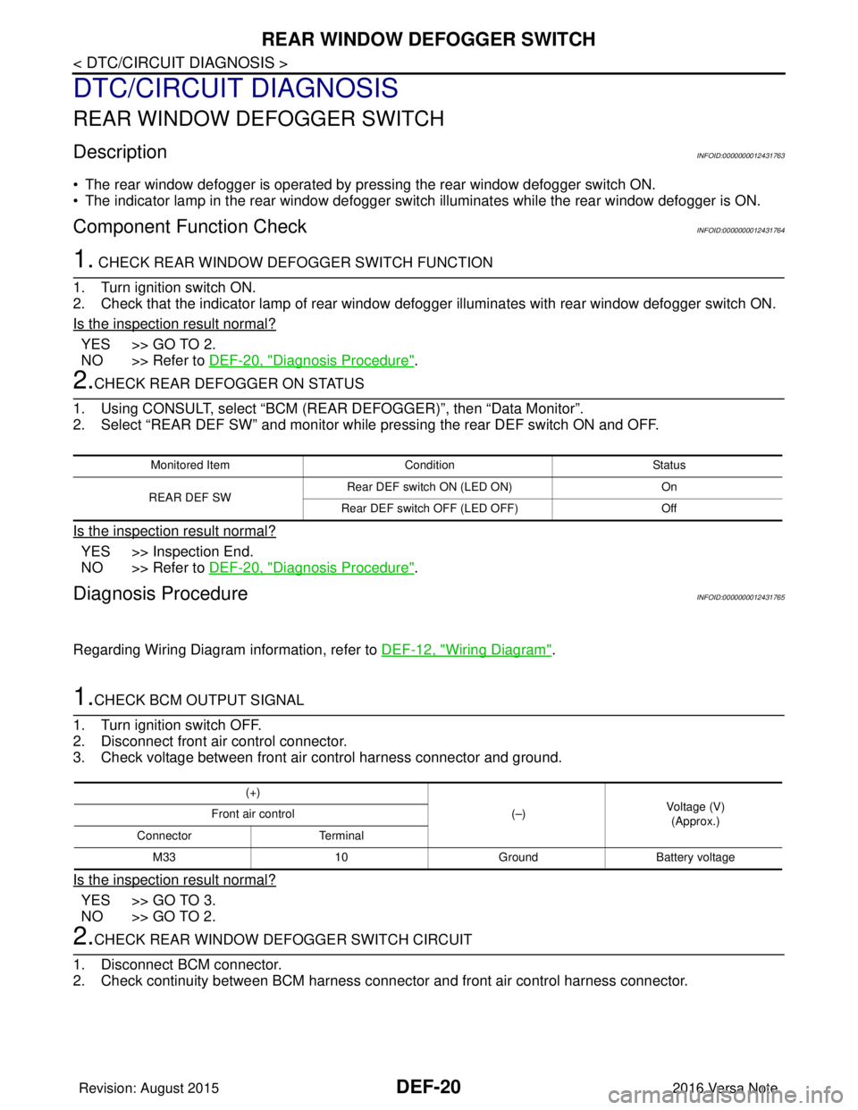
SYSTEM DIAGRAM
Operation Description
• When rear window defogger switch is turned ON while ignition switch is ON, the front air control (rear win-dow defogger switch) transmits rear window defogger switch signal to BCM.
• BCM turns rear window defogger relay ON when rear window defogger switch signal is received.
• Rear window defogger and door mirror defogger (with door mirror defogger) are supplied with power and operate when rear window defogger relay turns ON.
• Rear window defogger ON is displayed when front air control receives signals.
Timer function
• BCM turns rear window defogger relay ON for appr oximately 15 minutes when rear window defogger switch
is turned ON while ignition switch is ON. It makes rear window defogger and door mirror defogger (with door
mirror defogger) operate.
• Timer is canceled after pressing rear window defogger switch again during timer operation. Then BCM turns rear window defogger relay OFF. The same reaction also occurs during timer operation, if the ignition switch
is turned OFF.
INPUT/OUTPUT SIGNAL CHART
*: With door mirror defogger
ALLIA1028GB
Switch Input signal to BCM BCM functionActuator
Rear window defogger switch Defogger switch signal Rear window defogger and door
mirror defogger
* control Rear window defogger
Door mirror defogger *Ignition switch Ignition signal
Revision: August 2015 2016 Versa Note
cardiagn.com
Page 658 of 3641

DIAGNOSIS SYSTEM (BCM) (WITH INTELLIGENT KEY SYSTEM)
DEF-7
< SYSTEM DESCRIPTION >
C
D E
F
G H
I
J
K
M A
B
DEF
N
O P
DIAGNOSIS SYSTEM (BCM) (WIT H INTELLIGENT KEY SYSTEM)
COMMON ITEM
COMMON ITEM : CONSULT Function (BCM - COMMON ITEM)INFOID:0000000012542306
APPLICATION ITEM
CONSULT performs the following functions via CAN communication with BCM.
SYSTEM APPLICATION
BCM can perform the following functions.
Direct Diagnostic Mode Description
ECU Identification The BCM part number is displayed.
Self Diagnostic Result The BCM self diagnostic results are displayed.
Data Monitor The BCM input/output data is displayed in real time.
Active Test The BCM activates outputs to test components.
Work support The settings for BCM functions can be changed.
Configuration • The vehicle specification can be read and saved.
• The vehicle specification can be written when replacing BCM.
CAN DIAG SUPPORT MNTR The result of transmit/receive diagnosis of CAN communication is displayed.
System Sub System Direct Diagnostic Mode
ECU Identification
Self Diagnostic Result
Data Monitor
Active Test
Work support
Configuration
CAN DIAG SUPPORT MNTR
Door lock
DOOR LOCK ×××
Rear window defogger REAR DEFOGGER ××
Warning chime BUZZER ××
Interior room lamp timer INT LAMP ×××
Exterior lamp HEAD LAMP ×××
Wiper and washer WIPER ×××
Turn signal and hazard warning lamps FLASHER ×××
Air conditioner AIR CONDITIONER ×
Intelligent Key system INTELLIGENT KEY ××××
Combination switch COMB SW ×
BCM BCM× × ×××
Immobilizer IMMU ××××
Interior room lamp battery saver BATTERY SAVER ×××
Vehicle security system THEFT ALM ××
RAP system RETAINED PWR ×
Signal buffer system SIGNAL BUFFER ×
TPMS AIR PRESSURE MONITOR ××××
Panic alarm system PANIC ALARM ×
Revision: August 2015 2016 Versa Note
cardiagn.com
Page 660 of 3641

DIAGNOSIS SYSTEM (BCM) (WITHOUT INTELLIGENT KEY SYSTEM)DEF-9
< SYSTEM DESCRIPTION >
C
DE
F
G H
I
J
K
M A
B
DEF
N
O P
DIAGNOSIS SYSTEM (BCM) (WITHO UT INTELLIGENT KEY SYSTEM)
COMMON ITEM
COMMON ITEM : CONSULT Function (BCM - COMMON ITEM)INFOID:0000000012542309
APPLICATION ITEM
CONSULT performs the following functions via CAN communication with BCM.
SYSTEM APPLICATION
BCM can perform the following functions.
Direct Diagnostic Mode Description
ECU Identification The BCM part number is displayed.
Self Diagnostic Result The BCM self diagnostic results are displayed.
Data Monitor The BCM input/output data is displayed in real time.
Active Test The BCM activates outputs to test components.
Work support The settings for BCM functions can be changed.
Configuration • The vehicle specification can be read and saved.
• The vehicle specification can be written when replacing BCM.
CAN DIAG SUPPORT MNTR The result of transmit/receive diagnosis of CAN communication is displayed.
System Sub System Direct Diagnostic Mode
ECU Identification
Self Diagnostic Result
Data Monitor
Active Test
Work support
Configuration
CAN DIAG SUPPORT MNTR
Door lock
DOOR LOCK ×××
Rear window defogger REAR DEFOGGER ××
Warning chime BUZZER ××
Interior room lamp timer INT LAMP ×××
Remote keyless entry system MULTI REMOTE ENT ×××
Exterior lamp HEAD LAMP ×××
Wiper and washer WIPER ×××
Turn signal and hazard warning lamps FLASHER ××
Air conditioner AIR CONDITIONER ×
Combination switch COMB SW ×
BCM BCM× × ×××
Immobilizer IMMU ×××
Interior room lamp battery saver BATTERY SAVER ×××
Vehicle security system THEFT ALM ××
RAP system RETAINED PWR ××
Signal buffer system SIGNAL BUFFER ×
TPMS AIR PRESSURE MONITOR ××××
Panic alarm system PANIC ALARM ×
Revision: August 2015 2016 Versa Note
cardiagn.com
Page 671 of 3641

DEF-20
< DTC/CIRCUIT DIAGNOSIS >
REAR WINDOW DEFOGGER SWITCH
DTC/CIRCUIT DIAGNOSIS
REAR WINDOW DEFOGGER SWITCH
DescriptionINFOID:0000000012431763
• The rear window defogger is operated by pressing the rear window defogger switch ON.
• The indicator lamp in the rear window defogger switch illuminates while the rear window defogger is ON.
Component Function CheckINFOID:0000000012431764
1. CHECK REAR WINDOW DEFOGGER SWITCH FUNCTION
1. Turn ignition switch ON.
2. Check that the indicator lamp of rear window def ogger illuminates with rear window defogger switch ON.
Is the inspection result normal?
YES >> GO TO 2.
NO >> Refer to DEF-20, "
Diagnosis Procedure".
2.CHECK REAR DEFOGGER ON STATUS
1. Using CONSULT, select “BCM (REAR DEFOGGER)”, then “Data Monitor”.
2. Select “REAR DEF SW” and monitor while pressing the rear DEF switch ON and OFF.
Is the inspection result normal?
YES >> Inspection End.
NO >> Refer to DEF-20, "
Diagnosis Procedure".
Diagnosis ProcedureINFOID:0000000012431765
Regarding Wiring Diagram information, refer to DEF-12, "Wiring Diagram".
1.CHECK BCM OUTPUT SIGNAL
1. Turn ignition switch OFF.
2. Disconnect front air control connector.
3. Check voltage between front air control harness connector and ground.
Is the inspection result normal?
YES >> GO TO 3.
NO >> GO TO 2.
2.CHECK REAR WINDOW DEFOGGER SWITCH CIRCUIT
1. Disconnect BCM connector.
2. Check continuity between BCM harness connec tor and front air control harness connector.
Monitored ItemConditionStatus
REAR DEF SW Rear DEF switch ON (LED ON)
On
Rear DEF switch OFF (LED OFF) Off
(+)
(–)Voltage (V)
(Approx.)
Front air control
Connector Terminal
M33 10GroundBattery voltage
Revision: August 2015 2016 Versa Note
cardiagn.com
Page 703 of 3641
![NISSAN NOTE 2016 Service Repair Manual DLK-14
< SYSTEM DESCRIPTION >[WITH INTELLIGENT KEY SYSTEM]
COMPONENT PARTS
A. View with instrument panel assembly
removed B. View with glove box door removed C. View with front grille removed
D. View NISSAN NOTE 2016 Service Repair Manual DLK-14
< SYSTEM DESCRIPTION >[WITH INTELLIGENT KEY SYSTEM]
COMPONENT PARTS
A. View with instrument panel assembly
removed B. View with glove box door removed C. View with front grille removed
D. View](/manual-img/5/57363/w960_57363-702.png)
DLK-14
< SYSTEM DESCRIPTION >[WITH INTELLIGENT KEY SYSTEM]
COMPONENT PARTS
A. View with instrument panel assembly
removed B. View with glove box door removed C. View with front grille removed
D. View of LH door (RH similar) E. View of LH door switch (RH similar) F. View with rear bumper cover re- moved
G. View from rear of vehicle H. View with rear seat cushion removed I. View with center console removed
No. Component Function
1. Combination meter Combination meter transmits the vehicle speed sig-
nal to BCM via CAN communication.
BCM also receives the vehicle speed signal from
ABS actuator and electric uni
t (control unit) via CAN
communication. BCM compares both signals to de-
tect the vehicle speed.
Security indicator lamp is located on combination
meter.
Security indicator lamp blinks when ignition switch
is in any position other than ON to warn that NIS-
SAN VEHICLE IMMOBILIZER SYSTEM-NATS
[NVIS (NATS)] is on board.
Refer to MWI-59, "
METER SYSTEM : Combination
Meter".
2. Push-button ignition switch Push-button ignition switch has push switch inside
which detects that push-button ignition switch is
pressed, and then transmits ON/OFF signal to
BCM. BCM changes the ignition switch position with
the operation of push-button ignition switch. BCM
maintains the ignition switch position status while
push-button ignition switch is not operated.
3. BCM BCM controls INTELLIGENT KEY SYSTEM (EN-
GINE START FUNCTION), NISSAN VEHICLE IM-
MOBILIZER SYSTEM-NATS [NVIS (NATS)] and
VEHICLE SECURITY SYSTEM.
BCM performs the ID verification between BCM and
Intelligent Key when the Intelligent Key is carried
into the detection area of inside key antenna, and
push-button ignition switch is pressed. If the ID ver-
ification result is OK, ignition switch operation is
available.
Then, when the ignition switch is turned ON, BCM
performs ID verification between BCM and ECM. If
the ID verification result is OK, ECM can start en-
gine.
Refer to BCS-6, "
BODY CONTROL SYSTEM :
Component Parts Location" for detailed installation
location.
4. Main power window and door lock/unlock switch Door lock and unlock switch is integrated into the
main power window and door lock/unlock switch.
Door lock and unlock switch transmits door lock/un-
lock operation signal to BCM.
Refer to PWC-7, "
Main Power Window And Door
Lock/Unlock Switch".
5. Front door lock assembly LH Door key cylinder switch is integrated into front door
lock assembly (driver side).
Door key cylinder switch detects door LOCK/UN-
LOCK operation using mechanical key, and then
transmits the operation signal to BCM.
Refer to DLK-17, "
INTELLIGENT KEY SYSTEM :
Front Door Lock Asse
mbly (Driver Side)".
6. Rear door lock actuator LH Rear door lock actuator locks/unlocks the rear door
latch assembly.
Revision: August 2015
2016 Versa Note
cardiagn.com
Page 709 of 3641
![NISSAN NOTE 2016 Service Repair Manual DLK-20
< SYSTEM DESCRIPTION >[WITH INTELLIGENT KEY SYSTEM]
SYSTEM (POWER DOOR LOCK SYSTEM)
SYSTEM (POWER DOOR LOCK SYSTEM)
System DiagramINFOID:0000000012429981
System DescriptionINFOID:00000000124299 NISSAN NOTE 2016 Service Repair Manual DLK-20
< SYSTEM DESCRIPTION >[WITH INTELLIGENT KEY SYSTEM]
SYSTEM (POWER DOOR LOCK SYSTEM)
SYSTEM (POWER DOOR LOCK SYSTEM)
System DiagramINFOID:0000000012429981
System DescriptionINFOID:00000000124299](/manual-img/5/57363/w960_57363-708.png)
DLK-20
< SYSTEM DESCRIPTION >[WITH INTELLIGENT KEY SYSTEM]
SYSTEM (POWER DOOR LOCK SYSTEM)
SYSTEM (POWER DOOR LOCK SYSTEM)
System DiagramINFOID:0000000012429981
System DescriptionINFOID:0000000012429982
DOOR LOCK FUNCTION
• The door lock and unlock switch LH is built into the main power window and door lock/unlock switch.
• The door lock and unlock switch RH is built into
the power window and door lock/unlock switch RH.
• Interlocked with the locking operation of door lock and unlock switch, door lock actuators of all doors are
locked.
• Interlocked with the unlocking operation of door lock and unlock switch, door lock actuators of all doors are
unlocked.
Door Key Cylinder
• With the door key inserted in the door key cylinder on driver side, turning it to “LOCK”, will lock door lock actuator of all doors.
• With the door key inserted in the door key cylinder on driver side, turning it to “UNLOCK” onc\
e unlocks the driver side door lock actuator; turning it to “UNLOCK” again within 60 seconds after the first unlock operation
unlocks all of the other doors. - (SELECTIVE UNLOCK OPERATION)
Selective unlock operation mode can be changed using “A UTO LOCK SET” in “Work support”. Refer to BCS-
18, "DOOR LOCK : CONSULT Function (BCM - DOOR LOCK)".
AUTOMATIC DOOR LOCKS (LOCK OPERATION)
The automatic door locks function is the function that locks all doors linked with the vehicle speed or shift posi-
tion.
Vehicle Speed Sensing Auto Door Lock*1
All doors are locked when the vehicle speed reaches 24 km/h (15 MPH) or more.
BCM outputs the lock signal to all door lock actuators when it detects that the ignition switch is turned ON, all
doors are closed and the vehicle speed received from the combination meter via CAN communication
becomes 24 km/h (15 MPH) or more.
If a door is opened and closed at any time during one ignition cycle (OFF → ON), even after initial auto door
lock operation has taken place, the BCM will relock al l doors when the vehicle speed reaches 24 km/h (15
MPH) or more again.
ALKIA2288GB
Input SingleFunction Actuator
Door lock/unlock switch Door lock/unlock signal Door lock function
• Each door lock actuator
Door key cylinder switch
Each door switch
Door open/close signal
Key reminder function
Combination meter Warning buzzer signal
Vehicle speed signal
Automatic door lock/unlock
function
Revision: August 2015
2016 Versa Note
cardiagn.com