Page 2167 of 3641

INT-16
< REMOVAL AND INSTALLATION >
FRONT DOOR FINISHER
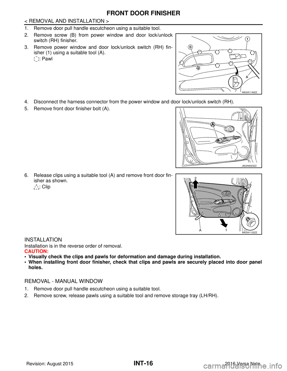
1. Remove door pull handle escutcheon using a suitable tool.
2. Remove screw (B) from power window and door lock/unlockswitch (RH) finisher.
3. Remove power window and door lock/unlock switch (RH) fin- isher (1) using a suitable tool (A).
: Pawl
4. Disconnect the harness connector from the pow er window and door lock/unlock switch (RH).
5. Remove front door finisher bolt (A).
6. Release clips using a suitable tool (A) and remove front door fin- isher as shown.
: Clip
INSTALLATION
Installation is in the reverse order of removal.
CAUTION:
• Visually check the clips and pawls for deformation and damage during installation.
• When installing front door finisher, check that cl ips and pawls are securely placed into door panel
holes.
REMOVAL - MANUAL WINDOW
1. Remove door pull handle escutcheon using a suitable tool.
2. Remove screw, release pawls using a suitable tool and remove storage tray (LH/RH).
AWJIA1140ZZ
JMJIA6023ZZ
AWJIA1122ZZ
Revision: August 2015 2016 Versa Note
cardiagn.com
Page 2168 of 3641
FRONT DOOR FINISHERINT-17
< REMOVAL AND INSTALLATION >
C
DE
F
G H
I
K L
M A
B
INT
N
O P
3. Release the metal clip (A) behind the manual window crank han- dle using a suitable tool (B). Pull the manual window crank han-
dle (3) outward from the front door finisher and remove handle.
4. Remove manual window crank handle.
5. Remove front door finisher bolt.
6. Release clips using a suitable tool (A) and remove front door fin- isher as shown.
(B): Protective tape
: Clip
INSTALLATION
Installation is in the reverse order of removal.
CAUTION:
• Visually check the clips and pawls for defo rmation and damage during installation.
• When installing front door finisher, check that clips and pawls are securely placed into door panel
holes.
AWJIA1119ZZ
AWJIA1083ZZ
Revision: August 2015 2016 Versa Note
cardiagn.com
Page 2169 of 3641
INT-18
< REMOVAL AND INSTALLATION >
REAR DOOR FINISHER
REAR DOOR FINISHER
Exploded ViewINFOID:0000000012431862
Removal and InstallationINFOID:0000000012431863
REMOVAL - POWER WINDOW
1. Release rear door corner finisher clip using a suitable tool.
2. Remove rear door pull handle escutcheon using a suitable tool. .
1. Rear door panel2. Rear door finisher3. Rear manual window door finisher
(if equipped)
4. Manual window crank washer (if equipped) 5. Manual window crank handle
(if equipped) 6. Rear door corner finisher
7. Manual window storage tray (if equipped) 8. Door pull handle escutcheon 9. Rear power window switch finisher
(if equipped)
A. Grommet ClipMetal Clip
Pawl
AWJIA1144ZZ
Revision: August 2015 2016 Versa Note
cardiagn.com
Page 2170 of 3641

REAR DOOR FINISHERINT-19
< REMOVAL AND INSTALLATION >
C
DE
F
G H
I
K L
M A
B
INT
N
O P
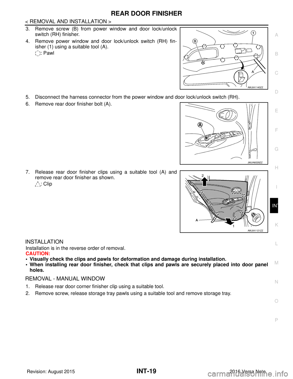
3. Remove screw (B) from power window and door lock/unlock switch (RH) finisher.
4. Remove power window and door lock/unlock switch (RH) fin- isher (1) using a suitable tool (A).
: Pawl
5. Disconnect the harness connector from the power window and door lock/unlock switch (RH).
6. Remove rear door finisher bolt (A).
7. Release rear door finisher clips using a suitable tool (A) and remove rear door finisher as shown.
: Clip
INSTALLATION
Installation is in the reverse order of removal.
CAUTION:
• Visually check the clips and pawls for defo rmation and damage during installation.
• When installing rear door finisher , check that clips and pawls are securely placed into door panel
holes.
REMOVAL - MANUAL WINDOW
1. Release rear door corner finisher clip using a suitable tool.
2. Remove screw, release storage tray pawls using a suitable tool and remove storage tray.
AWJIA1140ZZ
JMJIA6028ZZ
AWJIA1121ZZ
Revision: August 2015 2016 Versa Note
cardiagn.com
Page 2171 of 3641
INT-20
< REMOVAL AND INSTALLATION >
REAR DOOR FINISHER
3. Release the metal clip (A) behind the manual window crank han-dle using a suitable tool (B). Pull the manual window crank han-
dle (3) outward from the front door finisher and remove handle.
4. Remove rear door finisher bolt (A).
5. Release rear door finisher clips using a suitable tool (A) and remove rear door finisher as shown.
: Clip
INSTALLATION
Installation is in the reverse order of removal.
CAUTION:
• Visually check the clips and pawls for deformation and damage during installation.
• When installing rear door finisher, check that clips and pawls are securely placed into door panel
holes.
AWJIA1119ZZ
JMJIA6028ZZ
AWJIA1121ZZ
Revision: August 2015 2016 Versa Note
cardiagn.com
Page 2540 of 3641
![NISSAN NOTE 2016 Service Repair Manual PCS
DIAGNOSIS SYSTEM (BCM)PCS-37
< SYSTEM DESCRIPTION > [POWER DISTRIBUTION SYSTEM]
C
D
E
F
G H
I
J
K L
B A
O P
N
DIAGNOSIS SYSTEM (BCM)
COMMON ITEM
COMMON ITEM : CONSULT Function (BCM - COMMON ITEM)I NISSAN NOTE 2016 Service Repair Manual PCS
DIAGNOSIS SYSTEM (BCM)PCS-37
< SYSTEM DESCRIPTION > [POWER DISTRIBUTION SYSTEM]
C
D
E
F
G H
I
J
K L
B A
O P
N
DIAGNOSIS SYSTEM (BCM)
COMMON ITEM
COMMON ITEM : CONSULT Function (BCM - COMMON ITEM)I](/manual-img/5/57363/w960_57363-2539.png)
PCS
DIAGNOSIS SYSTEM (BCM)PCS-37
< SYSTEM DESCRIPTION > [POWER DISTRIBUTION SYSTEM]
C
D
E
F
G H
I
J
K L
B A
O P
N
DIAGNOSIS SYSTEM (BCM)
COMMON ITEM
COMMON ITEM : CONSULT Function (BCM - COMMON ITEM)INFOID:0000000012542491
APPLICATION ITEM
CONSULT performs the following functions via CAN communication with BCM.
SYSTEM APPLICATION
BCM can perform the following functions.
Direct Diagnostic Mode
Description
ECU Identification The BCM part number is displayed.
Self Diagnostic Result The BCM self diagnostic results are displayed.
Data Monitor The BCM input/output data is displayed in real time.
Active Test The BCM activates outputs to test components.
Work support The settings for BCM functions can be changed.
Configuration • The vehicle specification can be read and saved.
• The vehicle specification can be written when replacing BCM.
CAN DIAG SUPPORT MNTR The result of transmit/receive diagnosis of CAN communication is displayed.
System Sub System Direct Diagnostic Mode
ECU Identification
Self Diagnostic Result
Data Monitor
Active Test
Work support
Configuration
CAN DIAG SUPPORT MNTR
Door lock
DOOR LOCK ×××
Rear window defogger REAR DEFOGGER ××
Warning chime BUZZER ××
Interior room lamp timer INT LAMP ×××
Exterior lamp HEAD LAMP ×××
Wiper and washer WIPER ×××
Turn signal and hazard warning lamps FLASHER ×××
Air conditioner AIR CONDITIONER ×
Intelligent Key system INTELLIGENT KEY ××××
Combination switch COMB SW ×
BCM BCM× × ×××
Immobilizer IMMU ××××
Interior room lamp battery saver BATTERY SAVER ×××
Vehicle security system THEFT ALM ××
RAP system RETAINED PWR ×
Signal buffer system SIGNAL BUFFER ×
TPMS AIR PRESSURE MONITOR ××××
Panic alarm system PANIC ALARM ×
Revision: August 2015 2016 Versa Note
cardiagn.com
Page 2596 of 3641
PG
COMPONENT PARTSPG-9
< SYSTEM DESCRIPTION >
C
DE
F
G H
I
J
K L
B A
O P
N
COMPONENT PARTS
Circuit Breaker (Built Into BCM)INFOID:0000000012433116
For example, when current is 30A, the circuit is broken within 8 to 20
seconds.
This circuit breaker is used for the following systems:
• Power windows
Harness ConnectorINFOID:0000000012433117
HARNESS CONNECTOR (TAB-LOCKING TYPE)
• The tab-locking type connectors help prevent accidental looseness or disconnection.
• The tab-locking type connectors are disconnected by pushi
ng or lifting the locking tab(s). Refer to the figure
below.
Refer to the next page for description of the slide-locking type connector.
CAUTION:
Do not pull the harness or wires when disconnecting the connector.
SBF284E
Revision: August 2015 2016 Versa Note
cardiagn.com
Page 2631 of 3641

PG-44
< WIRING DIAGRAM >
HARNESS
C2 M6 W/4 : Dongle unitB1 M61 — : Body ground
B2 M7 W/16 : Door mirror remote control switch C1 M62 W/2 : Front blower motor
D1 M8 G/20 : Joint connector–M02 C3 M64 W/8 : Steering angle sensor
A3 M9 W/12 : To D1 E3 M65 W/4 : Front air control
D3 M10 L/20 : Joint connector–M01 D5 M66 B/3 : Console power socket
B4 M11 W/2 : To B28 A4 M69 SMJ : To E7
F3 M12 W/16 : To B29 E2 M70 W/20 : AV control unit
F3 M13 W/24 : To B30 D3 M71 W/24 : AV control unit
B3 M14 BR/6 : Rear window defogger relay F2 M75 Y/4 : To D101
B4 M15 W/16 : To B23 D2 M76 GR/5 : AV control unit
A4 M16 W/24 : To B24 E1 M77 Y/4 : Front passenger air bag module
D5 M17 B/1 : Parking brake switch A4 M78 B/2 :To E11
A2 M18 W/40 : BCM (Body contro
l module) (Without
Intelligent Key system) F1 M79 — : Body ground
A1 M19 W/15 : BCM (Body contro
l module) (Without
Intelligent Key system) A 3 M 8 0 Y / 4 : T o D 3
A2 M20 B/15 : BCM (Body contro
l module) (Without
Intelligent Key system) F2 M81 W/12 : To D115
C2 M21 W/4 : NATS antenna amp. C1 M82 W/40 : Combination meter (With type A)
B3 M22 W/16 : Data link connector D5 M83 B/3 : G sensor
E 4 M 2 3 W / 4 : Remote keyless entry receiver (Without
Intelligent Key system) E2 M84 — : Body ground
C1 M24 W/40 : Combination meter (With type B) E2 M85 — : Body ground
C4 M25 W/8 : Push–button ignition swtich F5 M89 L/2 : Inside key antenna (Console)
C3 M26 W/6 : Ignition switch E1 M90 B/4: Remote keyless entry receiver (With
Intelligent Key system without tire pressure
monitoring system)
C2 M27 BR/2 : Key switch F2 M92 W/12 : To D116
C3 M28 W/16 : Combination switch A3 M93 W/24 : To D16
E 3 M 2 9 W / 2 4 : T o B 1 F 1 M 9 4 W / 4: Remote keyless entry receiver (With
Intelligent Key system with tire pressure
monitoring system)
C4 M30 GR/8 : Combination switch (Spiral cable) D3 M95 L/2 : Inside key antenna (Instrument center)
C3 M31 Y/6 : Combination switch (Spiral cable) A2 M97 B/40 : BCM (Body contro
l module) (With
Intelligent Key system)
E5 M32 W/16 : To M201 A2 M98 W/40: BCM (Body contro
l module) (With
Intelligent Key system)
E3 M33 B/15 : Front air control A2 M99 W/15: BCM (Body contro
l module) (With
Intelligent Key system)
B3 M34 GR/6 : VDC off switch A2 M100 B / 1 5: BCM (Body contro
l module) (With
Intelligent Key system)
D4 M35 Y/28 : Air bag diagnosis sensor unit D2 M101 W/16 : Audio unit (With base audio system)
D1 M36 BR/2 : Front passenger air bag off indicator A3 M103 W/12 : Accessory prewire LH
E4 M38 W/8 : CVT shift selector E2 M104 W/12 : Accessory prewire RH
B3 M39 L/4 : Accessory relay–2 C2 M151 BR/4 : Front blower motor resistor
E2 M40 W/32 : Audio unit (With display audio system) Console sub harness
B3 M41 B/5 : Back door lock actuator relay E5 M201 W / 1 6 : T o M 3 2
C3 M42 BR/4 : Thermo control amp. E4 M202 B/3 : Console power socket
E2 M43 W/20 : Audio unit (With base audio system) C4 M203 BR/6 : Heated seat swtich RH
Revision: August 2015 2016 Versa Note
cardiagn.com