2016 NISSAN NOTE window
[x] Cancel search: windowPage 3329 of 3641
![NISSAN NOTE 2016 Service Repair Manual TM-88
< SYSTEM DESCRIPTION >[CVT: RE0F11A]
SYSTEM
Provides idle neutral control when st
op/start operation is not performed.
Idle Neutral Control Start Condition
Idle neutral control is started when NISSAN NOTE 2016 Service Repair Manual TM-88
< SYSTEM DESCRIPTION >[CVT: RE0F11A]
SYSTEM
Provides idle neutral control when st
op/start operation is not performed.
Idle Neutral Control Start Condition
Idle neutral control is started when](/manual-img/5/57363/w960_57363-3328.png)
TM-88
< SYSTEM DESCRIPTION >[CVT: RE0F11A]
SYSTEM
Provides idle neutral control when st
op/start operation is not performed.
Idle Neutral Control Start Condition
Idle neutral control is started when all of the following conditions are fulfilled. However, during idle neutral con-
trol, idle neutral control is stopped when any of the following conditions is not met or idle neutral control contin-
ues 30 seconds.
NOTE:
Stops or prohibits the idle neutral control when the TC M and ECM detect that the vehicle is in one of the fol-
lowing conditions.
• Engine coolant temperature and CVT fluid temperature are the specified temperature or more, or the speci-
fied temperature or less.
• When a transaxle malfunction occurs.
• When the vehicle detects DTC and is in the fail-safe mode.
• When idle speed increases due to heavy electric load*. *: When any one of rear window defogger switch, A/C s witch, headlamp, fog lamp is turned ON. In addition,
when the steering wheel is operated.
JPDIA1215GB
Driving environment : Flat road or road with mild gradient
Selector lever position : “D” position
Vehicle speed : 0 km/h (0 MPH)
Accelerator pedal position : 0.0/8
Brake pedal : Depressed
Engine speed : Idle speed
Turn signal lamp/hazard signal lamp : Not activated
Revision: August 2015 2016 Versa Note
cardiagn.com
Page 3536 of 3641

WCS
DIAGNOSIS SYSTEM (BCM) (WITH INTELLIGENT KEY SYSTEM)
WCS-21
< SYSTEM DESCRIPTION >
C
D E
F
G H
I
J
K L
M B A
O P
DIAGNOSIS SYSTEM (BCM) (WIT H INTELLIGENT KEY SYSTEM)
COMMON ITEM
COMMON ITEM : CONSULT Function (BCM - COMMON ITEM)INFOID:0000000012542986
APPLICATION ITEM
CONSULT performs the following functions via CAN communication with BCM.
SYSTEM APPLICATION
BCM can perform the following functions.
Direct Diagnostic Mode Description
ECU Identification The BCM part number is displayed.
Self Diagnostic Result The BCM self diagnostic results are displayed.
Data Monitor The BCM input/output data is displayed in real time.
Active Test The BCM activates outputs to test components.
Work support The settings for BCM functions can be changed.
Configuration • The vehicle specification can be read and saved.
• The vehicle specification can be written when replacing BCM.
CAN DIAG SUPPORT MNTR The result of transmit/receive diagnosis of CAN communication is displayed.
System Sub System Direct Diagnostic Mode
ECU Identification
Self Diagnostic Result
Data Monitor
Active Test
Work support
Configuration
CAN DIAG SUPPORT MNTR
Door lock
DOOR LOCK ×××
Rear window defogger REAR DEFOGGER ××
Warning chime BUZZER ××
Interior room lamp timer INT LAMP ×××
Exterior lamp HEAD LAMP ×××
Wiper and washer WIPER ×××
Turn signal and hazard warning lamps FLASHER ×××
Air conditioner AIR CONDITIONER ×
Intelligent Key system INTELLIGENT KEY ××××
Combination switch COMB SW ×
BCM BCM× × ×××
Immobilizer IMMU ××××
Interior room lamp battery saver BATTERY SAVER ×××
Vehicle security system THEFT ALM ××
RAP system RETAINED PWR ×
Signal buffer system SIGNAL BUFFER ×
TPMS AIR PRESSURE MONITOR ××××
Panic alarm system PANIC ALARM ×
Revision: August 2015 2016 Versa Note
cardiagn.com
Page 3538 of 3641

WCS
DIAGNOSIS SYSTEM (BCM) (WITHOUT INTELLIGENT KEY SYSTEM)WCS-23
< SYSTEM DESCRIPTION >
C
DE
F
G H
I
J
K L
M B A
O P
DIAGNOSIS SYSTEM (BCM) (WITHO UT INTELLIGENT KEY SYSTEM)
COMMON ITEM
COMMON ITEM : CONSULT Function (BCM - COMMON ITEM)INFOID:0000000012542988
APPLICATION ITEM
CONSULT performs the following functions via CAN communication with BCM.
SYSTEM APPLICATION
BCM can perform the following functions.
Direct Diagnostic Mode Description
ECU Identification The BCM part number is displayed.
Self Diagnostic Result The BCM self diagnostic results are displayed.
Data Monitor The BCM input/output data is displayed in real time.
Active Test The BCM activates outputs to test components.
Work support The settings for BCM functions can be changed.
Configuration • The vehicle specification can be read and saved.
• The vehicle specification can be written when replacing BCM.
CAN DIAG SUPPORT MNTR The result of transmit/receive diagnosis of CAN communication is displayed.
System Sub System Direct Diagnostic Mode
ECU Identification
Self Diagnostic Result
Data Monitor
Active Test
Work support
Configuration
CAN DIAG SUPPORT MNTR
Door lock
DOOR LOCK ×××
Rear window defogger REAR DEFOGGER ××
Warning chime BUZZER ××
Interior room lamp timer INT LAMP ×××
Remote keyless entry system MULTI REMOTE ENT ×××
Exterior lamp HEAD LAMP ×××
Wiper and washer WIPER ×××
Turn signal and hazard warning lamps FLASHER ××
Air conditioner AIR CONDITIONER ×
Combination switch COMB SW ×
BCM BCM× × ×××
Immobilizer IMMU ×××
Interior room lamp battery saver BATTERY SAVER ×××
Vehicle security system THEFT ALM ××
RAP system RETAINED PWR ××
Signal buffer system SIGNAL BUFFER ×
TPMS AIR PRESSURE MONITOR ××××
Panic alarm system PANIC ALARM ×
Revision: August 2015 2016 Versa Note
cardiagn.com
Page 3578 of 3641

DIAGNOSIS SYSTEM (BCM) (WITH INTELLIGENT KEY SYSTEM)
WW-13
< SYSTEM DESCRIPTION >
C
D E
F
G H
I
J
K
M A
B
WW
N
O P
DIAGNOSIS SYSTEM (BCM) (WIT H INTELLIGENT KEY SYSTEM)
COMMON ITEM
COMMON ITEM : CONSULT Function (BCM - COMMON ITEM)INFOID:0000000012542535
APPLICATION ITEM
CONSULT performs the following functions via CAN communication with BCM.
SYSTEM APPLICATION
BCM can perform the following functions.
Direct Diagnostic Mode Description
ECU Identification The BCM part number is displayed.
Self Diagnostic Result The BCM self diagnostic results are displayed.
Data Monitor The BCM input/output data is displayed in real time.
Active Test The BCM activates outputs to test components.
Work support The settings for BCM functions can be changed.
Configuration • The vehicle specification can be read and saved.
• The vehicle specification can be written when replacing BCM.
CAN DIAG SUPPORT MNTR The result of transmit/receive diagnosis of CAN communication is displayed.
System Sub System Direct Diagnostic Mode
ECU Identification
Self Diagnostic Result
Data Monitor
Active Test
Work support
Configuration
CAN DIAG SUPPORT MNTR
Door lock
DOOR LOCK ×××
Rear window defogger REAR DEFOGGER ××
Warning chime BUZZER ××
Interior room lamp timer INT LAMP ×××
Exterior lamp HEAD LAMP ×××
Wiper and washer WIPER ×××
Turn signal and hazard warning lamps FLASHER ×××
Air conditioner AIR CONDITIONER ×
Intelligent Key system INTELLIGENT KEY ××××
Combination switch COMB SW ×
BCM BCM× × ×××
Immobilizer IMMU ××××
Interior room lamp battery saver BATTERY SAVER ×××
Vehicle security system THEFT ALM ××
RAP system RETAINED PWR ×
Signal buffer system SIGNAL BUFFER ×
TPMS AIR PRESSURE MONITOR ××××
Panic alarm system PANIC ALARM ×
Revision: August 2015 2016 Versa Note
cardiagn.com
Page 3580 of 3641

DIAGNOSIS SYSTEM (BCM) (WITHOUT INTELLIGENT KEY SYSTEM)WW-15
< SYSTEM DESCRIPTION >
C
DE
F
G H
I
J
K
M A
B
WW
N
O P
DIAGNOSIS SYSTEM (BCM) (WITHO UT INTELLIGENT KEY SYSTEM)
COMMON ITEM
COMMON ITEM : CONSULT Function (BCM - COMMON ITEM)INFOID:0000000012542537
APPLICATION ITEM
CONSULT performs the following functions via CAN communication with BCM.
SYSTEM APPLICATION
BCM can perform the following functions.
Direct Diagnostic Mode Description
ECU Identification The BCM part number is displayed.
Self Diagnostic Result The BCM self diagnostic results are displayed.
Data Monitor The BCM input/output data is displayed in real time.
Active Test The BCM activates outputs to test components.
Work support The settings for BCM functions can be changed.
Configuration • The vehicle specification can be read and saved.
• The vehicle specification can be written when replacing BCM.
CAN DIAG SUPPORT MNTR The result of transmit/receive diagnosis of CAN communication is displayed.
System Sub System Direct Diagnostic Mode
ECU Identification
Self Diagnostic Result
Data Monitor
Active Test
Work support
Configuration
CAN DIAG SUPPORT MNTR
Door lock
DOOR LOCK ×××
Rear window defogger REAR DEFOGGER ××
Warning chime BUZZER ××
Interior room lamp timer INT LAMP ×××
Remote keyless entry system MULTI REMOTE ENT ×××
Exterior lamp HEAD LAMP ×××
Wiper and washer WIPER ×××
Turn signal and hazard warning lamps FLASHER ××
Air conditioner AIR CONDITIONER ×
Combination switch COMB SW ×
BCM BCM× × ×××
Immobilizer IMMU ×××
Interior room lamp battery saver BATTERY SAVER ×××
Vehicle security system THEFT ALM ××
RAP system RETAINED PWR ××
Signal buffer system SIGNAL BUFFER ×
TPMS AIR PRESSURE MONITOR ××××
Panic alarm system PANIC ALARM ×
Revision: August 2015 2016 Versa Note
cardiagn.com
Page 3635 of 3641

WW-70
< REMOVAL AND INSTALLATION >
REAR WIPER ARM
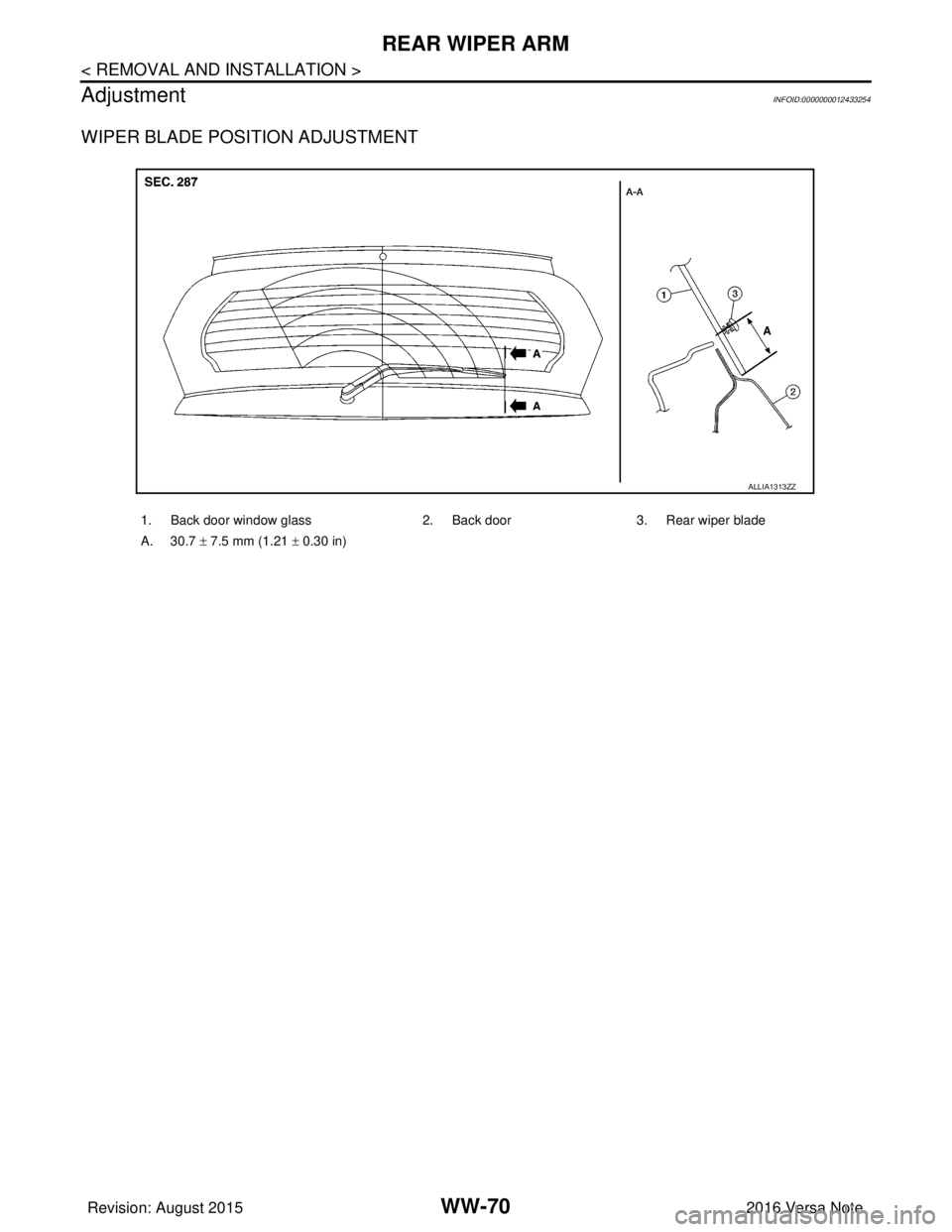
Adjustment
INFOID:0000000012433254
WIPER BLADE POSITION ADJUSTMENT
1. Back door window glass 2. Back door3. Rear wiper blade
A. 30.7 ± 7.5 mm (1.21 ± 0.30 in)
ALLIA1313ZZ
Revision: August 2015 2016 Versa Note
cardiagn.com
Page 3636 of 3641

REAR WIPER BLADEWW-71
< REMOVAL AND INSTALLATION >
C
DE
F
G H
I
J
K
M A
B
WW
N
O P
REAR WIPER BLADE
Removal and InstallationINFOID:0000000012433255
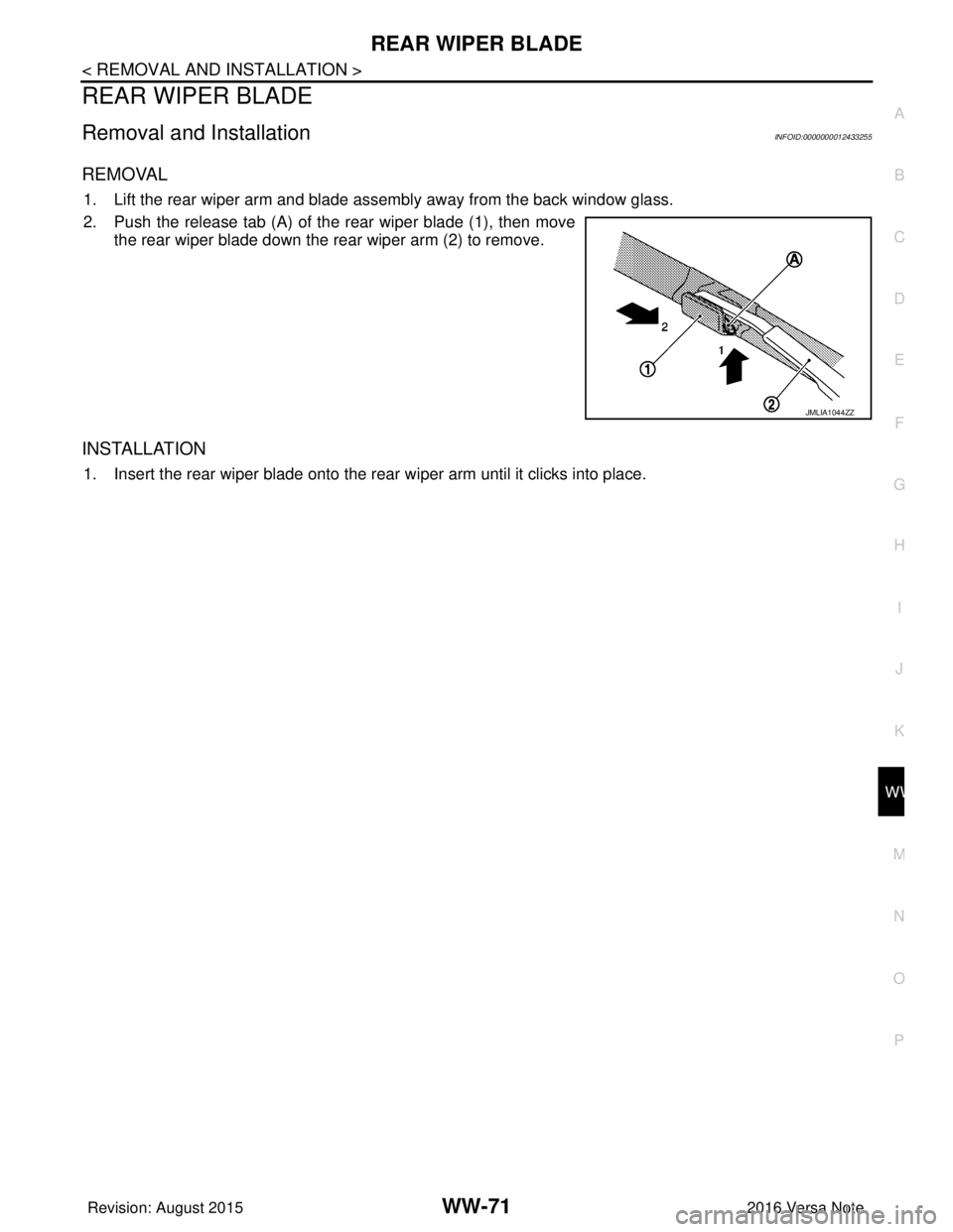
REMOVAL
1. Lift the rear wiper arm and blade assembly away from the back window glass.
2. Push the release tab (A) of the rear wiper blade (1), then move the rear wiper blade down the rear wiper arm (2) to remove.
INSTALLATION
1. Insert the rear wiper blade onto the rear wiper arm until it clicks into place.
JMLIA1044ZZ
Revision: August 2015 2016 Versa Note
cardiagn.com
Page 3639 of 3641

WW-74
< REMOVAL AND INSTALLATION >
REAR WASHER NOZZLE AND TUBE
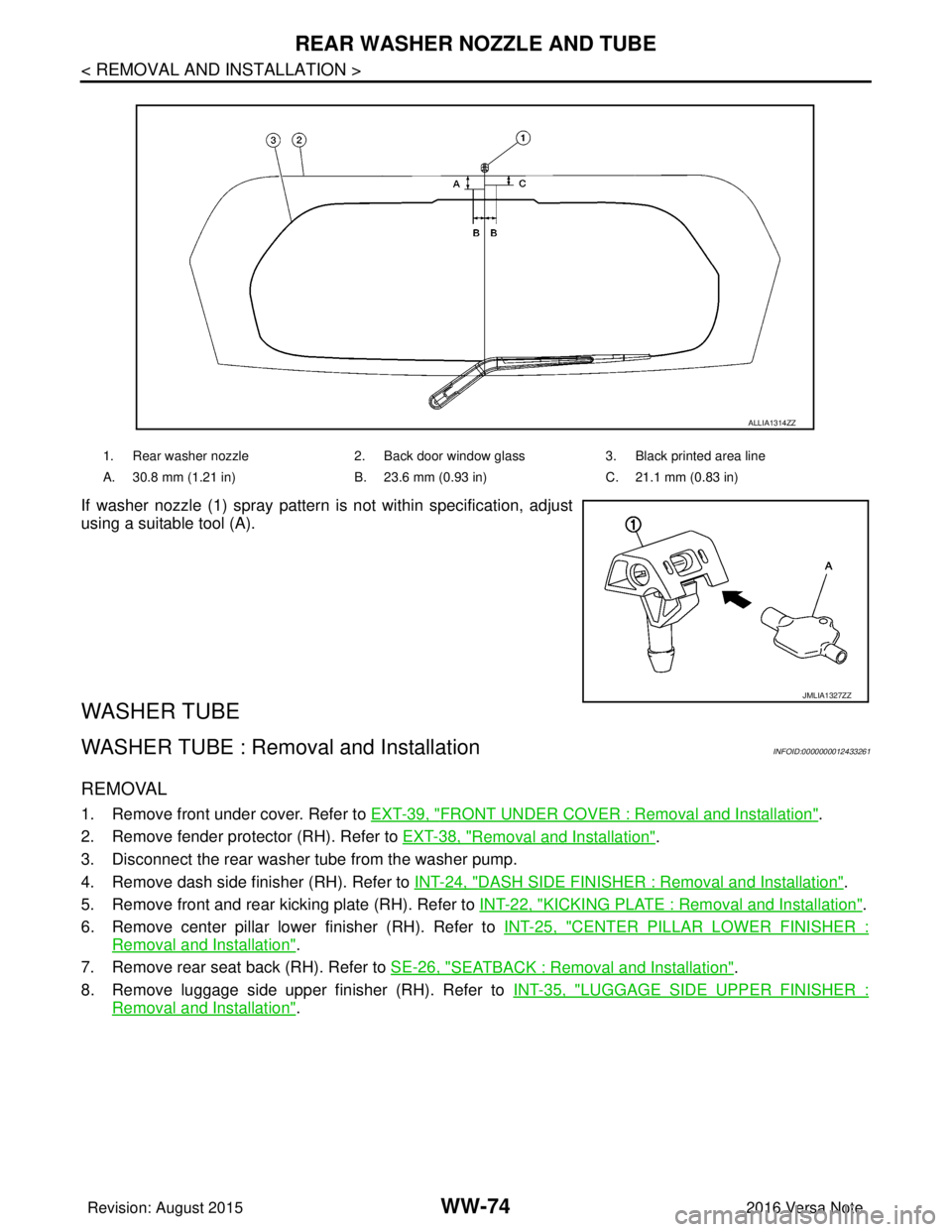
If washer nozzle (1) spray pattern is not within specification, adjust
using a suitable tool (A).
WASHER TUBE
WASHER TUBE : Removal and InstallationINFOID:0000000012433261
REMOVAL
1. Remove front under cover. Refer to EXT-39, "FRONT UNDER COVER : Removal and Installation".
2. Remove fender protector (RH). Refer to EXT-38, "
Removal and Installation".
3. Disconnect the rear washer tube from the washer pump.
4. Remove dash side finisher (RH). Refer to INT-24, "
DASH SIDE FINISHER : Removal and Installation".
5. Remove front and rear kicking plate (RH). Refer to INT-22, "
KICKING PLATE : Removal and Installation".
6. Remove center pillar lower finisher (RH). Refer to INT-25, "
CENTER PILLAR LOWER FINISHER :
Removal and Installation".
7. Remove rear seat back (RH). Refer to SE-26, "
SEATBACK : Removal and Installation".
8. Remove luggage side upper finisher (RH). Refer to INT-35, "
LUGGAGE SIDE UPPER FINISHER :
Removal and Installation".
1. Rear washer nozzle2. Back door window glass3. Black printed area line
A. 30.8 mm (1.21 in) B. 23.6 mm (0.93 in)C. 21.1 mm (0.83 in)
ALLIA1314ZZ
JMLIA1327ZZ
Revision: August 2015 2016 Versa Note
cardiagn.com