2016 NISSAN NOTE belt
[x] Cancel search: beltPage 2095 of 3641

INL-1
DRIVER CONTROLS
C
DE
F
G H
I
J
K
M
SECTION INL
A
B
INL
N
O P
CONTENTS
INTERIOR LIGHTING SYSTEM
PRECAUTION ....... ........................................3
PRECAUTIONS .............................................. .....3
Precaution for Supplemental Restraint System
(SRS) "AIR BAG" and "SEAT BELT PRE-TEN-
SIONER" ............................................................. ......
3
Precaution for Work ..................................................3
PREPARATION ............................................4
PREPARATION .............................................. .....4
Special Service Tool ........................................... ......4
SYSTEM DESCRIPTION ..............................5
COMPONENT PARTS ................................... .....5
Component Parts Location .................................. ......5
SYSTEM ..............................................................7
INTERIOR ROOM LAMP CONTROL SYSTEM .... ......7
INTERIOR ROOM LAMP CONTROL SYSTEM :
System Description ...................................................
7
ILLUMINATION CONTROL SYSTEM ................... ......9
ILLUMINATION CONTROL SYSTEM : System
Description ................................................................
9
DIAGNOSIS SYSTEM (BCM) (WITH INTELLI-
GENT KEY SYSTEM) .........................................
10
COMMON ITEM ..................................................... ....10
COMMON ITEM : CONSULT Function (BCM -
COMMON ITEM) .....................................................
10
DOOR LOCK ......................................................... ....11
DOOR LOCK : CONSULT Function (BCM -
DOOR LOCK) .........................................................
11
INT LAMP .............................................................. ....11
INT LAMP : CONSULT Function (BCM - INT
LAMP) .....................................................................
11
INTELLIGENT KEY ............................................... ....12
INTELLIGENT KEY : CONSULT Function (BCM -
INTELLIGENT KEY) ................................................
12
BATTERY SAVER ................................................. ....14
BATTERY SAVER : CONSULT Function (BCM -
BATTERY SAVER) ..................................................
14
DIAGNOSIS SYSTEM (BCM) (WITHOUT IN-
TELLIGENT KEY SYSTEM) .............................
16
COMMON ITEM ..................................................... ....16
COMMON ITEM : CONSULT Function (BCM -
COMMON ITEM) .....................................................
16
DOOR LOCK .......................................................... ....17
DOOR LOCK : CONSULT Function (BCM -
DOOR LOCK) ..........................................................
17
INT LAMP ............................................................... ....17
INT LAMP : CONSULT Function (BCM - INT
LAMP) ......................................................................
18
BATTERY SAVER ................................................. ....19
BATTERY SAVER : CONSULT Function (BCM -
BATTERY SAVER) ..................................................
19
ECU DIAGNOSIS INFO RMATION ..............20
BCM ...................................................................20
List of ECU Reference ......................................... ....20
WIRING DIAGRAM ......................................21
INTERIOR ROOM LAMP CONTROL SYSTEM
...
21
Wiring Diagram .................................................... ....21
ILLUMINATION .................................................28
Wiring Diagram ........................................................28
BASIC INSPECTION ...................................37
DIAGNOSIS AND REPAIR WORKFLOW ........37
Work Flow ............................................................ ....37
Revision: August 2015 2016 Versa Note
cardiagn.com
Page 2097 of 3641
PRECAUTIONSINL-3
< PRECAUTION >
C
DE
F
G H
I
J
K
M A
B
INL
N
O P
PRECAUTION
PRECAUTIONS
Precaution for Supplemental Restraint System (SRS) "AIR BAG" and "SEAT BELT
PRE-TENSIONER"
INFOID:0000000012432718
The Supplemental Restraint System such as “AIR BAG” and “SEAT BELT PRE-TENSIONER”, used along
with a front seat belt, helps to reduce the risk or severi ty of injury to the driver and front passenger for certain
types of collision. Information necessary to service the system safely is included in the SR and SB section of
this Service Manual.
WARNING:
• To avoid rendering the SRS inoper ative, which could increase the risk of personal injury or death in
the event of a collision which would result in air bag inflation, all maintenance must be performed by
an authorized NISSAN/INFINITI dealer.
• Improper maintenance, including in correct removal and installation of the SRS, can lead to personal
injury caused by unintentional act ivation of the system. For removal of Spiral Cable and Air Bag
Module, see the SR section.
• Do not use electrical test equipm ent on any circuit related to the SRS unless instructed to in this
Service Manual. SRS wiring harnesses can be identi fied by yellow and/or orange harnesses or har-
ness connectors.
PRECAUTIONS WHEN USING POWER TOOLS (AIR OR ELECTRIC) AND HAMMERS
WARNING:
• When working near the Airbag Diagnosis Sensor Un it or other Airbag System sensors with the Igni-
tion ON or engine running, DO NOT use air or el ectric power tools or strike near the sensor(s) with a
hammer. Heavy vibration could activate the sensor( s) and deploy the air bag(s), possibly causing
serious injury.
• When using air or electric power tools or hammers, always switch the Ignition OFF, disconnect the
battery and wait at least three mi nutes before performing any service.
Precaution for WorkINFOID:0000000012432719
• When removing or disassembling each component, be ca reful not to damage or deform it. If a component
may be subject to interference, be sure to protect it with a shop cloth.
• When removing (disengaging) components with a screwdriver or similar tool, be sure to wrap the component with a shop cloth or vinyl tape to protect it.
• Protect the removed parts with a shop cloth and prevent them from being dropped.
• Replace a deformed or damaged clip.
• If a part is specified as a non-reusabl e part, always replace it with a new one.
• Be sure to tighten bolts and nuts securely to the specified torque.
• After installation is complete, be sure to check that each part works properly.
• Follow the steps below to clean components:
- Water soluble dirt:
• Dip a soft cloth into lukewarm water, wring the water out of the cloth and wipe the dirty area.
• Then rub with a soft, dry cloth.
-Oily dirt:
• Dip a soft cloth into lukewarm water with mild detergent (concentration: within 2 to 3%) and wipe the dirty
area.
• Then dip a cloth into fresh water, wring the water out of the cloth and wipe the detergent off.
• Then rub with a soft, dry cloth.
- Do not use organic solvent such as thinner, benzene, alcohol or gasoline.
- For genuine leather seats, use a genuine leather seat cleaner.
Revision: August 2015 2016 Versa Note
cardiagn.com
Page 2152 of 3641

INT-1
BODY INTERIOR
C
DE
F
G H
I
K L
M
SECTION INT
A
B
INT
N
O P
CONTENTS
INTERIOR
PRECAUTION ....... ........................................3
PRECAUTIONS .............................................. .....3
Precaution for Supplemental Restraint System
(SRS) "AIR BAG" and "SEAT BELT PRE-TEN-
SIONER" ............................................................. ......
3
Precaution for Work ..................................................3
PREPARATION ............................................4
PREPARATION .............................................. .....4
Special Service Tools .......................................... ......4
Commercial Service Tools ........................................4
CLIP LIST ............................................................5
Descriptions for Clips ................................................5
SYMPTOM DIAGNOSIS ...............................9
SQUEAK AND RATTLE TROUBLE DIAG-
NOSES ........................ ........................................
9
Work Flow ........................................................... ......9
Generic Squeak and Rattle Troubleshooting ..........10
Diagnostic Worksheet .............................................13
REMOVAL AND INSTALLATION ...............15
FRONT DOOR FINISHER .............................. ....15
Exploded View .................................................... ....15
Removal and Installation .........................................15
REAR DOOR FINISHER ................................ ....18
Exploded View .................................................... ....18
Removal and Installation .........................................18
BODY SIDE TRIM .......................................... ....21
Exploded View .................................................... ....21
FRONT PILLAR FINISHER ................................... ....21
FRONT PILLAR FINISHER : Removal and Instal-
lation .................................................................... ....
21
KICKING PLATE ................................................... ....22
KICKING PLATE : Removal and Installation ...........22
DASH SIDE FINISHER .......................................... ....24
DASH SIDE FINISHER : Removal and Installation
....
24
BODY SIDE WELT ................................................. ....24
BODY SIDE WELT : Removal and Installation ........24
CENTER PILLAR LOWER FINISHER ................... ....25
CENTER PILLAR LOWER FINISHER : Removal
and Installation ........................................................
25
CENTER PILLAR UPPER FINISHER ........................25
CENTER PILLAR UPPER FINISHER : Removal
and Installation .................................................... ....
25
FLOOR TRIM ....................................................27
Exploded View .........................................................27
Removal and Installation .........................................27
HEADLINING ....................................................30
Exploded View .........................................................30
Removal and Installation .........................................31
LUGGAGE TRIM ...............................................33
Exploded View .........................................................33
LUGGAGE REAR PLATE ..................................... ....33
LUGGAGE REAR PLATE : Removal and Installa-
tion ...........................................................................
34
LUGGAGE SIDE LOWER FINISHER .................... ....34
LUGGAGE SIDE LOWER FINISHER : Removal
and Installation ........................................................
34
LUGGAGE SIDE UPPER FINISHER .........................35
LUGGAGE SIDE UPPER FINISHER : Removal
and Installation .................................................... ....
35
BACK DOOR TRIM ...........................................36
Exploded View ..................................................... ....36
BACK DOOR INNER FINISHER ........................... ....36
Revision: August 2015 2016 Versa Note
cardiagn.com
Page 2154 of 3641
PRECAUTIONSINT-3
< PRECAUTION >
C
DE
F
G H
I
K L
M A
B
INT
N
O P
PRECAUTION
PRECAUTIONS
Precaution for Supplemental Restraint System (SRS) "AIR BAG" and "SEAT BELT
PRE-TENSIONER"
INFOID:0000000012431852
The Supplemental Restraint System such as “AIR BAG” and “SEAT BELT PRE-TENSIONER”, used along
with a front seat belt, helps to reduce the risk or severi ty of injury to the driver and front passenger for certain
types of collision. Information necessary to service the system safely is included in the SR and SB section of
this Service Manual.
WARNING:
• To avoid rendering the SRS inoper ative, which could increase the risk of personal injury or death in
the event of a collision which would result in air bag inflation, all maintenance must be performed by
an authorized NISSAN/INFINITI dealer.
• Improper maintenance, including in correct removal and installation of the SRS, can lead to personal
injury caused by unintentional act ivation of the system. For removal of Spiral Cable and Air Bag
Module, see the SR section.
• Do not use electrical test equipm ent on any circuit related to the SRS unless instructed to in this
Service Manual. SRS wiring harnesses can be identi fied by yellow and/or orange harnesses or har-
ness connectors.
PRECAUTIONS WHEN USING POWER TOOLS (AIR OR ELECTRIC) AND HAMMERS
WARNING:
• When working near the Airbag Diagnosis Sensor Un it or other Airbag System sensors with the Igni-
tion ON or engine running, DO NOT use air or el ectric power tools or strike near the sensor(s) with a
hammer. Heavy vibration could activate the sensor( s) and deploy the air bag(s), possibly causing
serious injury.
• When using air or electric power tools or hammers, always switch the Ignition OFF, disconnect the
battery and wait at least three mi nutes before performing any service.
Precaution for WorkINFOID:0000000012431853
• When removing or disassembling each component, be ca reful not to damage or deform it. If a component
may be subject to interference, be sure to protect it with a shop cloth.
• When removing (disengaging) components with a screwdriver or similar tool, be sure to wrap the component with a shop cloth or vinyl tape to protect it.
• Protect the removed parts with a shop cloth and prevent them from being dropped.
• Replace a deformed or damaged clip.
• If a part is specified as a non-reusabl e part, always replace it with a new one.
• Be sure to tighten bolts and nuts securely to the specified torque.
• After installation is complete, be sure to check that each part works properly.
• Follow the steps below to clean components:
- Water soluble dirt:
• Dip a soft cloth into lukewarm water, wring the water out of the cloth and wipe the dirty area.
• Then rub with a soft, dry cloth.
-Oily dirt:
• Dip a soft cloth into lukewarm water with mild detergent (concentration: within 2 to 3%) and wipe the dirty
area.
• Then dip a cloth into fresh water, wring the water out of the cloth and wipe the detergent off.
• Then rub with a soft, dry cloth.
- Do not use organic solvent such as thinner, benzene, alcohol or gasoline.
- For genuine leather seats, use a genuine leather seat cleaner.
Revision: August 2015 2016 Versa Note
cardiagn.com
Page 2176 of 3641
BODY SIDE TRIMINT-25
< REMOVAL AND INSTALLATION >
C
DE
F
G H
I
K L
M A
B
INT
N
O P
Installation
Installation is in the reverse order of removal.
CENTER PILLAR LOWER FINISHER
CENTER PILLAR LOWER FINISHER
: Removal and InstallationINFOID:0000000012431869
REMOVAL
1. Remove front kicking plate and rear kicking plate. Refer to INT-22, "KICKING PLATE : Removal and
Installation".
2. Remove center pillar lower finisher as shown.
INSTALLATION
Installation is in the reverse order of removal.
CAUTION:
• Visually check the pawls and clips for deformation and damage during installation. Replace compo-
nent if necessary.
CENTER PILLAR UPPER FINISHER
CENTER PILLAR UPPER FINISHER : Removal and InstallationINFOID:0000000012431870
REMOVAL
CAUTION:
• Be careful not to apply excessive for ce when removing center pillar upper finisher. Otherwise, clip
may be damaged and fragments may drop in body panels.
1. Slide front seat to the full forward position.
2. Release pawls, using a suitable tool and remove the seat belt height adjuster finisher (1).
: Pawl
3. Remove front D-ring anchor bolt. CAUTION:
Before removing D-ring anchor bolt note the positions of washers and spacers for correct installa-
tion.
4. Remove front body side welt and rear body side welt. Refer to INT-24, "
BODY SIDE WELT : Removal and
Installation".
5. Remove center pillar lower finisher. Refer to INT-25, "
CENTER PILLAR LOWER FINISHER : Removal
and Installation".
6. Release center pillar upper finisher upper clip using a suitable tool as shown. CAUTION:
JMJIA6045ZZ
AWHIA0539ZZ
Revision: August 2015 2016 Versa Note
cardiagn.com
Page 2178 of 3641
FLOOR TRIMINT-27
< REMOVAL AND INSTALLATION >
C
DE
F
G H
I
K L
M A
B
INT
N
O P
FLOOR TRIM
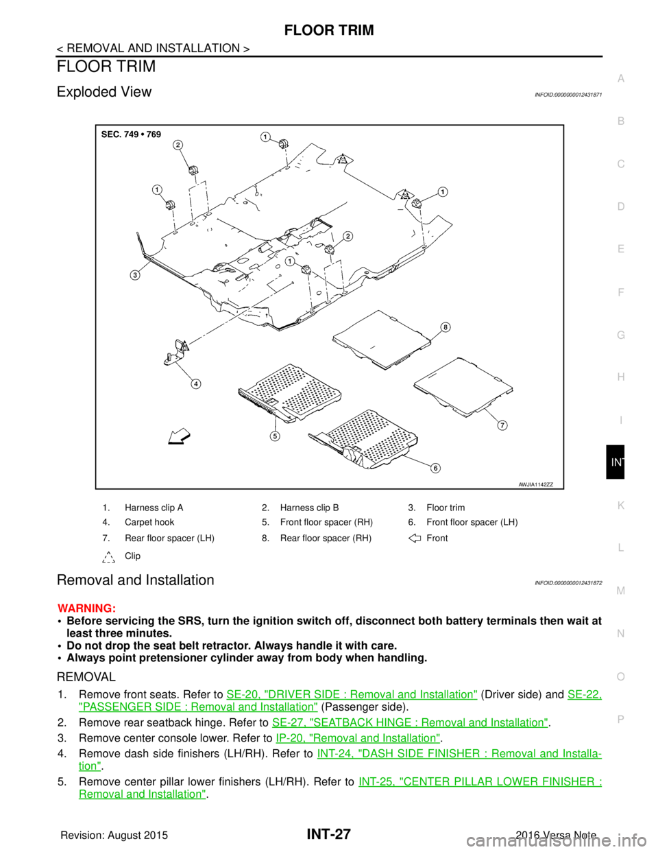
Exploded ViewINFOID:0000000012431871
Removal and InstallationINFOID:0000000012431872
WARNING:
• Before servicing the SRS, turn the ignition switch off, disconnect both battery terminals then wait at
least three minutes.
• Do not drop the seat belt retractor. Always handle it with care.
• Always point pretensioner cylinder away from body when handling.
REMOVAL
1. Remove front seats. Refer to SE-20, "DRIVER SIDE : Removal and Installation" (Driver side) and SE-22,
"PASSENGER SIDE : Removal and Installation" (Passenger side).
2. Remove rear seatback hinge. Refer to SE-27, "
SEATBACK HINGE : Removal and Installation".
3. Remove center console lower. Refer to IP-20, "
Removal and Installation".
4. Remove dash side finishers (LH/RH). Refer to INT-24, "
DASH SIDE FINISHER : Removal and Installa-
tion".
5. Remove center pillar lower finishers (LH/RH). Refer to INT-25, "
CENTER PILLAR LOWER FINISHER :
Removal and Installation".
1. Harness clip A2. Harness clip B3. Floor trim
4. Carpet hook 5. Front floor spacer (RH) 6. Front floor spacer (LH)
7. Rear floor spacer (LH) 8. Rear floor spacer (RH) Front
Clip
AWJIA1142ZZ
Revision: August 2015 2016 Versa Note
cardiagn.com
Page 2179 of 3641
INT-28
< REMOVAL AND INSTALLATION >
FLOOR TRIM
6. Disconnect negative and positive battery terminals, then wait at least three minutes. Refer to PG-70,
"Removal and Installation (Battery)".
WARNING:
Before servicing the SRS, turn th e ignition switch off, disconnect both battery terminals then wait
at least three minutes.
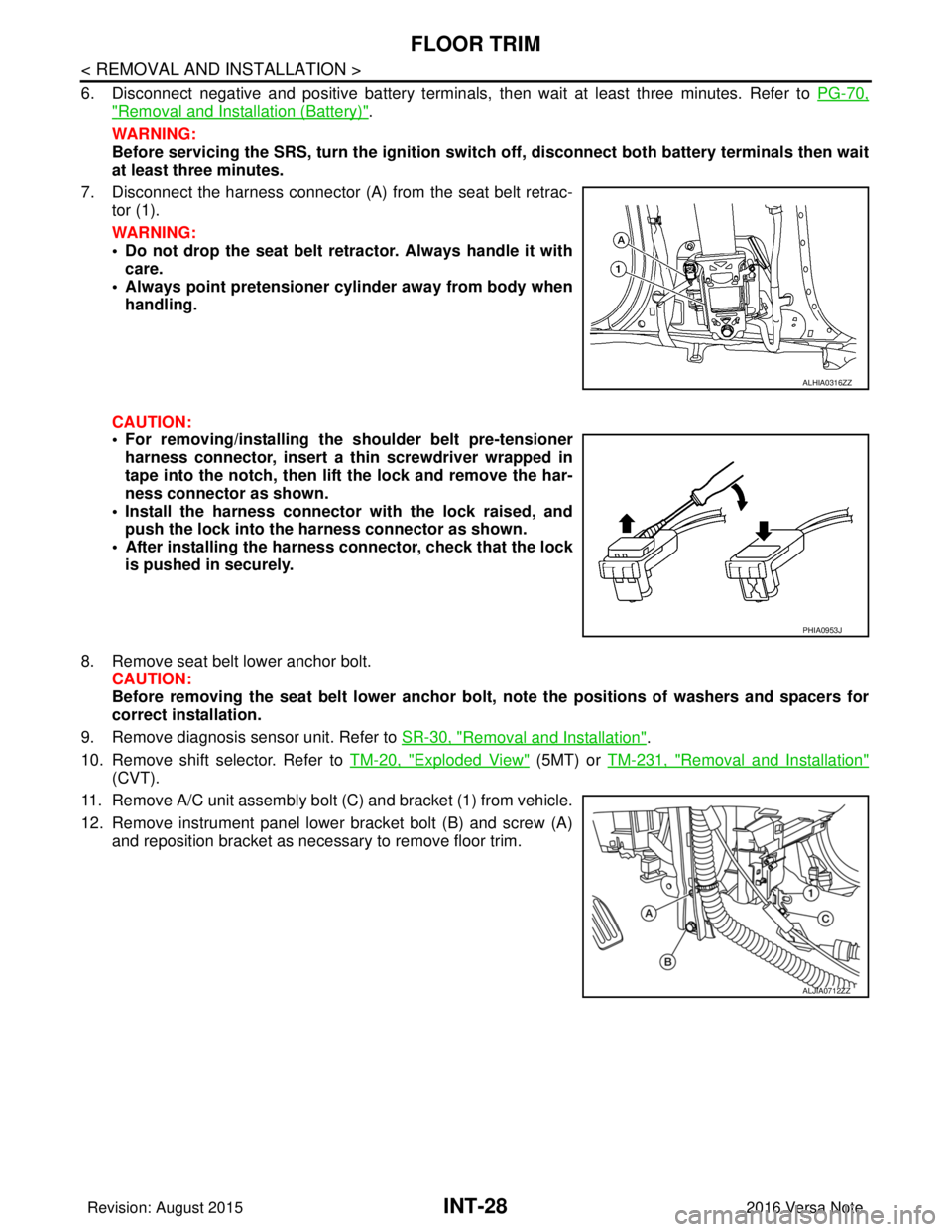
7. Disconnect the harness connector (A ) from the seat belt retrac-
tor (1).
WARNING:
• Do not drop the seat belt retractor. Always handle it with care.
• Always point pretensioner cylinder away from body when handling.
CAUTION:
• For removing/installing the shoulder belt pre-tensioner harness connector, insert a thin screwdriver wrapped in
tape into the notch, then lift the lock and remove the har-
ness connector as shown.
• Install the harness connector with the lock raised, and push the lock into the harness connector as shown.
• After installing the harness connector, check that the lock
is pushed in securely.
8. Remove seat belt lower anchor bolt. CAUTION:
Before removing the seat belt lower anchor bolt , note the positions of washers and spacers for
correct installation.
9. Remove diagnosis sensor unit. Refer to SR-30, "
Removal and Installation".
10. Remove shift selector. Refer to TM-20, "
Exploded View" (5MT) or TM-231, "Removal and Installation"
(CVT).
11. Remove A/C unit assembly bolt (C) and bracket (1) from vehicle.
12. Remove instrument panel lower bracket bolt (B) and screw (A) and reposition bracket as necessary to remove floor trim.
ALHIA0316ZZ
PHIA0953J
ALJIA0712ZZ
Revision: August 2015 2016 Versa Note
cardiagn.com
Page 2186 of 3641
LUGGAGE TRIMINT-35
< REMOVAL AND INSTALLATION >
C
DE
F
G H
I
K L
M A
B
INT
N
O P
: Pawl
7. Release the harness connector from cargo room lamp (RH only) and remove luggage side lower finisher.
INSTALLATION
Installation is in the reverse order of removal.
CAUTION:
• Visually check the clips and pawls for defo rmation and damage during installation.
• When installing lu ggage side clip, press luggag e side clip so that upper side stamp mark faces
toward passenger room, and then completely engage luggage side clip pawls.
LUGGAGE SIDE UPPER FINISHER
LUGGAGE SIDE UPPER FINISHER : Removal and InstallationINFOID:0000000012431878
REMOVAL
1. Remove luggage side lower finisher. Refer to INT-34, "LUGGAGE SIDE LOWER FINISHER : Removal
and Installation".
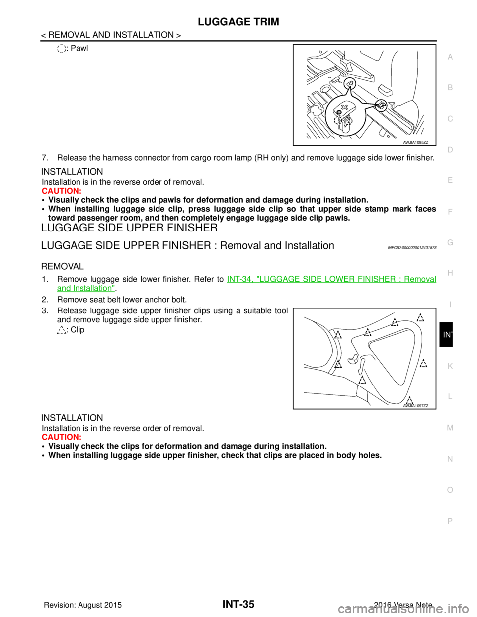
2. Remove seat belt lower anchor bolt.
3. Release luggage side upper finisher clips using a suitable tool and remove luggage side upper finisher.
: Clip
INSTALLATION
Installation is in the reverse order of removal.
CAUTION:
• Visually check the clips for deformation and damage during installation.
• When installing luggage side upper finisher, check that clips are placed in body holes.
AWJIA1095ZZ
AWJIA1097ZZ
Revision: August 2015 2016 Versa Note
cardiagn.com