2016 NISSAN NOTE belt
[x] Cancel search: beltPage 2028 of 3641
PRECAUTIONSHA-3
< PRECAUTION >
C
DE
F
G H
J
K L
M A
B
HA
N
O P
PRECAUTION
PRECAUTIONS
Precaution for Supplemental Restraint System (SRS) "AIR BAG" and "SEAT BELT
PRE-TENSIONER"
INFOID:0000000012431985
The Supplemental Restraint System such as “AIR BAG” and “SEAT BELT PRE-TENSIONER”, used along
with a front seat belt, helps to reduce the risk or severi ty of injury to the driver and front passenger for certain
types of collision. Information necessary to service the system safely is included in the SR and SB section of
this Service Manual.
WARNING:
• To avoid rendering the SRS inoper ative, which could increase the risk of personal injury or death in
the event of a collision which would result in air bag inflation, all maintenance must be performed by
an authorized NISSAN/INFINITI dealer.
• Improper maintenance, including in correct removal and installation of the SRS, can lead to personal
injury caused by unintentional act ivation of the system. For removal of Spiral Cable and Air Bag
Module, see the SR section.
• Do not use electrical test equipm ent on any circuit related to the SRS unless instructed to in this
Service Manual. SRS wiring harnesses can be identi fied by yellow and/or orange harnesses or har-
ness connectors.
PRECAUTIONS WHEN USING POWER TOOLS (AIR OR ELECTRIC) AND HAMMERS
WARNING:
• When working near the Airbag Diagnosis Sensor Un it or other Airbag System sensors with the Igni-
tion ON or engine running, DO NOT use air or el ectric power tools or strike near the sensor(s) with a
hammer. Heavy vibration could activate the sensor( s) and deploy the air bag(s), possibly causing
serious injury.
• When using air or electric power tools or hammers, always switch the Ignition OFF, disconnect the
battery and wait at least three mi nutes before performing any service.
Precaution for WorkINFOID:0000000012918336
• When removing or disassembling each component, be ca reful not to damage or deform it. If a component
may be subject to interference, be sure to protect it with a shop cloth.
• When removing (disengaging) components with a screwdriver or similar tool, be sure to wrap the component with a shop cloth or vinyl tape to protect it.
• Protect the removed parts with a shop cloth and prevent them from being dropped.
• Replace a deformed or damaged clip.
• If a part is specified as a non-reusabl e part, always replace it with a new one.
• Be sure to tighten bolts and nuts securely to the specified torque.
• After installation is complete, be sure to check that each part works properly.
• Follow the steps below to clean components:
- Water soluble dirt:
• Dip a soft cloth into lukewarm water, wring the water out of the cloth and wipe the dirty area.
• Then rub with a soft, dry cloth.
-Oily dirt:
• Dip a soft cloth into lukewarm water with mild detergent (concentration: within 2 to 3%) and wipe the dirty
area.
• Then dip a cloth into fresh water, wring the water out of the cloth and wipe the detergent off.
• Then rub with a soft, dry cloth.
- Do not use organic solvent such as thinner, benzene, alcohol or gasoline.
- For genuine leather seats, use a genuine leather seat cleaner.
Revision: August 2015 2016 Versa Note
cardiagn.com
Page 2042 of 3641
NOISEHA-17
< SYMPTOM DIAGNOSIS >
C
DE
F
G H
J
K L
M A
B
HA
N
O P
NOISE
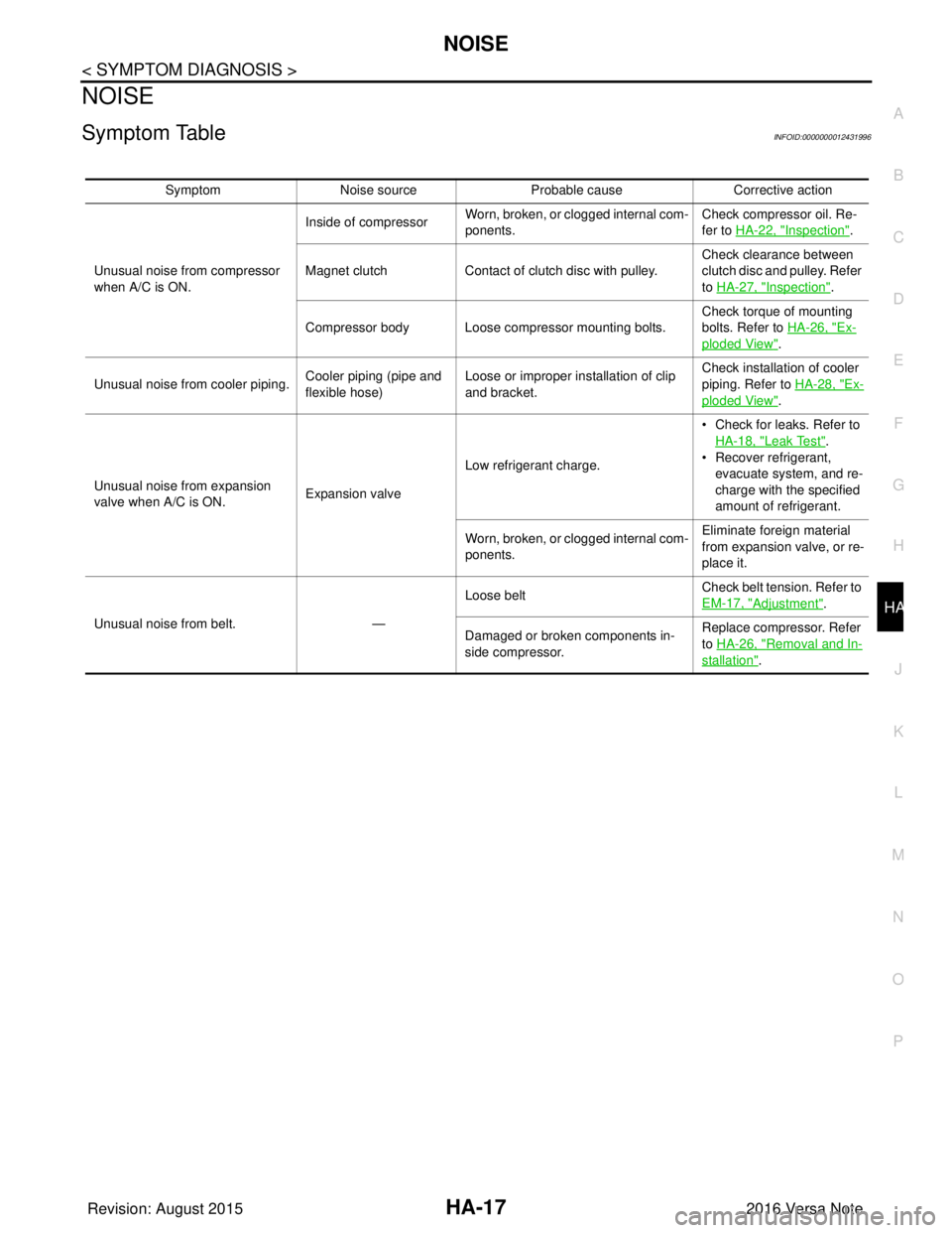
Symptom TableINFOID:0000000012431996
Symptom Noise source Probable cause Corrective action
Unusual noise from compressor
when A/C is ON. Inside of compressor
Worn, broken, or clogged internal com-
ponents. Check compressor oil. Re-
fer to HA-22, "
Inspection".
Magnet clutch Contact of clutch disc with pulley. Check clearance between
clutch disc and pulley. Refer
to HA-27, "
Inspection".
Compressor body Loose compressor mounting bolts. Check torque of mounting
bolts. Refer to
HA-26, "
Ex-
ploded View".
Unusual noise from cooler piping. Cooler piping (pipe and
flexible hose)Loose or improper installation of clip
and bracket. Check installation of cooler
piping. Refer to
HA-28, "
Ex-
ploded View".
Unusual noise from expansion
valve when A/C is ON. Expansion valveLow refrigerant charge. • Check for leaks. Refer to
HA-18, "
Leak Test".
• Recover refrigerant,
evacuate system, and re-
charge with the specified
amount of refrigerant.
Worn, broken, or clogged internal com-
ponents. Eliminate foreign material
from expansion valve, or re-
place it.
Unusual noise from belt. —Loose belt
Check belt tension. Refer to
EM-17, "
Adjustment".
Damaged or broken components in-
side compressor. Replace compressor. Refer
to HA-26, "
Removal and In-
stallation".
Revision: August 2015
2016 Versa Note
cardiagn.com
Page 2051 of 3641
HA-26
< REMOVAL AND INSTALLATION >
COMPRESSOR
REMOVAL AND INSTALLATION
COMPRESSOR
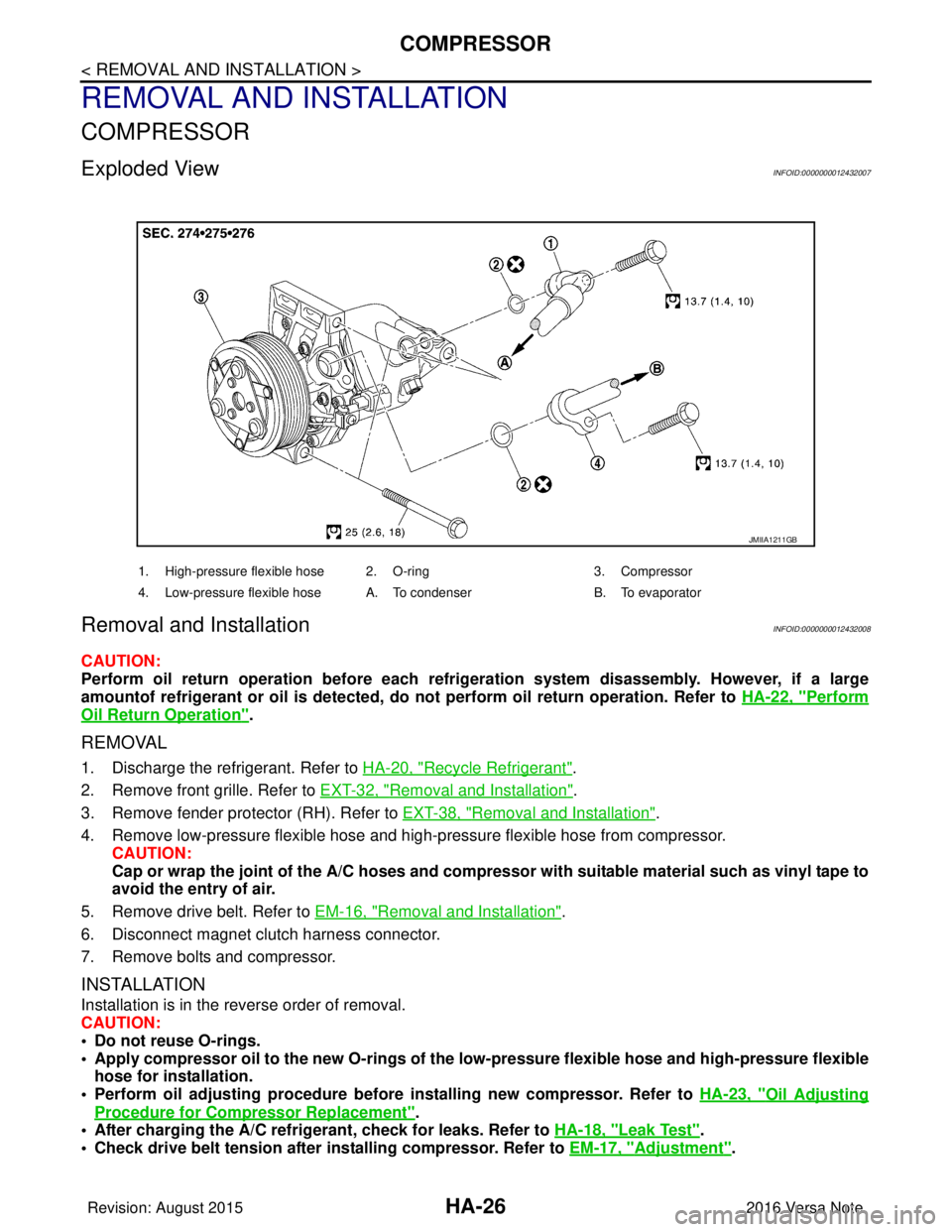
Exploded ViewINFOID:0000000012432007
Removal and InstallationINFOID:0000000012432008
CAUTION:
Perform oil return operation before each refrigeration system disassembly. However, if a large
amountof refrigerant or oil is detected, do not perform oil return operation. Refer to HA-22, "
Perform
Oil Return Operation".
REMOVAL
1. Discharge the refrigerant. Refer to HA-20, "Recycle Refrigerant".
2. Remove front grille. Refer to EXT-32, "
Removal and Installation".
3. Remove fender protector (RH). Refer to EXT-38, "
Removal and Installation".
4. Remove low-pressure flexible hose and high-pressure flexible hose from compressor. CAUTION:
Cap or wrap the joint of the A/C hoses and compr essor with suitable material such as vinyl tape to
avoid the entry of air.
5. Remove drive belt. Refer to EM-16, "
Removal and Installation".
6. Disconnect magnet clutch harness connector.
7. Remove bolts and compressor.
INSTALLATION
Installation is in the reverse order of removal.
CAUTION:
• Do not reuse O-rings.
• Apply compressor oil to the new O-rings of the low-pressure flexible hose an d high-pressure flexible
hose for installation.
• Perform oil adjusting procedure before installing new compressor. Refer to HA-23, "
Oil Adjusting
Procedure for Compressor Replacement".
• After charging the A/C refrig erant, check for leaks. Refer to HA-18, "
Leak Test".
• Check drive belt tension after installing compressor. Refer to EM-17, "
Adjustment".
JMIIA1211GB
1. High-pressure flexible hose 2. O-ring 3. Compressor
4. Low-pressure flexible hose A. To condenser B. To evaporator
Revision: August 2015 2016 Versa Note
cardiagn.com
Page 2062 of 3641
SERVICE DATA AND SPECIFICATIONS (SDS)HA-37
< SERVICE DATA AND SPECIFICATIONS (SDS)
C
DE
F
G H
J
K L
M A
B
HA
N
O P
SERVICE DATA AND SPECIFICATIONS (SDS)
SERVICE DATA AND SPECIFICATIONS (SDS)
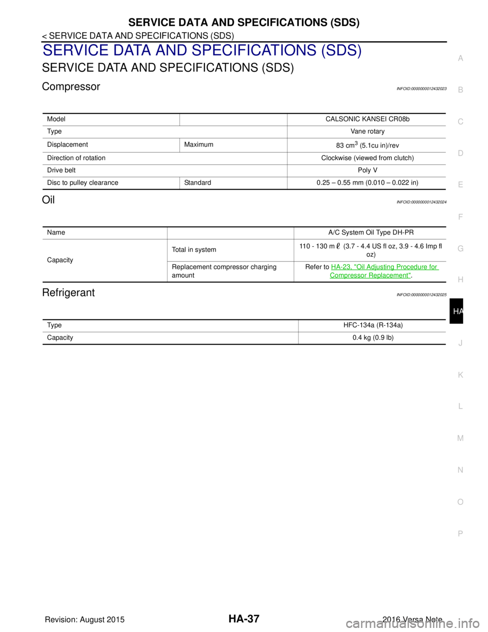
CompressorINFOID:0000000012432023
OilINFOID:0000000012432024
RefrigerantINFOID:0000000012432025
Model CALSONIC KANSEI CR08b
Ty p e Vane rotary
Displacement Maximum 83 cm
3 (5.1cu in)/rev
Direction of rotation Clockwise (viewed from clutch)
Drive belt Poly V
Disc to pulley clearance Standard0.25 – 0.55 mm (0.010 – 0.022 in)
Name A/C System Oil Type DH-PR
Capacity Total in system
110 - 130 m (3.7 - 4.4 US fl oz, 3.9 - 4.6 Imp fl
oz)
Replacement compressor charging
amount Refer to
HA-23, "
Oil Adjusting Procedure for
Compressor Replacement".
Ty p e HFC-134a (R-134a)
Capacity 0.4 kg (0.9 lb)
Revision: August 20152016 Versa Note
cardiagn.com
Page 2063 of 3641

HRN-1
DRIVER CONTROLS
C
DE
F
G H
I
J
K
M
SECTION HRN
A
B
HRN
N
O P
CONTENTS
HORN
PRECAUTION ....... ........................................2
PRECAUTIONS .............................................. .....2
Precaution for Supplemental Restraint System
(SRS) "AIR BAG" and "SEAT BELT PRE-TEN-
SIONER" ............................................................. ......
2
WIRING DIAGRAM .......................................3
HORN .................................................................3
Wiring Diagram .................................................... .....3
REMOVAL AND INSTALLATION ................6
HORN .................................................................6
Exploded View ..................................................... .....6
Removal and Installation ..........................................6
Revision: August 2015 2016 Versa Note
cardiagn.com
Page 2064 of 3641
HRN-2
< PRECAUTION >
PRECAUTIONS
PRECAUTION
PRECAUTIONS
Precaution for Supplemental Restraint System (SRS) "AIR BAG" and "SEAT BELT
PRE-TENSIONER"
INFOID:0000000012431935
The Supplemental Restraint System such as “A IR BAG” and “SEAT BELT PRE-TENSIONER”, used along
with a front seat belt, helps to reduce the risk or severity of injury to the driver and front passenger for certain
types of collision. Information necessary to service the system safely is included in the SR and SB section of
this Service Manual.
WARNING:
• To avoid rendering the SRS inopera tive, which could increase the risk of personal injury or death in
the event of a collision which would result in air bag inflation, all maintenance must be performed by
an authorized NISSAN/INFINITI dealer.
• Improper maintenance, including in correct removal and installation of the SRS, can lead to personal
injury caused by unintent ional activation of the system. For re moval of Spiral Cable and Air Bag
Module, see the SR section.
• Do not use electrical test equipmen t on any circuit related to the SRS unless instructed to in this
Service Manual. SRS wiring harn esses can be identified by yellow and/or orange harnesses or har-
ness connectors.
PRECAUTIONS WHEN USING POWER TOOLS (AIR OR ELECTRIC) AND HAMMERS
WARNING:
• When working near the Airbag Diagnosis Sensor Unit or other Airbag System sensors with the Igni-
tion ON or engine running, DO NOT use air or electri c power tools or strike near the sensor(s) with a
hammer. Heavy vibration could activate the sensor( s) and deploy the air bag(s), possibly causing
serious injury.
• When using air or electric power tools or hammers , always switch the Ignition OFF, disconnect the
battery and wait at least three minutes before performing any service.
Revision: August 2015 2016 Versa Note
cardiagn.com
Page 2069 of 3641

IP-1
BODY INTERIOR
C
DE
F
G H
I
K L
M
SECTION IP
A
B
IP
N
O P
CONTENTS
INSTRUMENT PANEL
PRECAUTION ....... ........................................2
PRECAUTIONS .............................................. .....2
Precaution for Supplemental Restraint System
(SRS) "AIR BAG" and "SEAT BELT PRE-TEN-
SIONER" ............................................................. ......
2
Precaution for Work ..................................................2
PREPARATION ............................................3
PREPARATION .............................................. .....3
Special Service Tools ........................................ ......3
Commercial Service Tools .......................................3
CLIP LIST ............................................................4
Descriptions for Clips ................................................4
SYMPTOM DIAGNOSIS ...............................8
SQUEAK AND RATTLE TROUBLE DIAG-
NOSES ........................ ........................................
8
Work Flow ........................................................... ......8
Generic Squeak and Rattle Troubleshooting ............9
Diagnostic Worksheet .............................................12
REMOVAL AND INSTALLATION ...............14
INSTRUMENT PANEL ASSEMBLY .............. ....14
Exploded View .................................................... ....14
Removal and Installation ..................................... ....15
STEERING COLUMN COVERS .......................17
Removal and Installation .........................................17
CENTER CONSOLE ASSEMBLY ....................18
Exploded View .........................................................18
Removal and Installation .........................................18
CENTER CONSOLE LOWER ...........................20
Removal and Installation .........................................20
CLUSTER LID A ...............................................21
Removal and Installation .........................................21
CLUSTER LID C ...............................................22
Removal and Installation .........................................22
FRONT AIR CONTROL FINISHER ...................23
Removal and Installation .........................................23
INSTRUMENT LOWER PANEL LH ..................24
Removal and Installation .........................................24
GLOVE BOX ASSEMBLY ................................25
Removal and Installation .........................................25
UPPER GLOVE BOX ........................................26
Removal and Installation ..................................... ....26
Revision: August 2015 2016 Versa Note
cardiagn.com
Page 2070 of 3641
IP-2
< PRECAUTION >
PRECAUTIONS
PRECAUTION
PRECAUTIONS
Precaution for Supplemental Restraint System (SRS) "AIR BAG" and "SEAT BELT
PRE-TENSIONER"
INFOID:0000000012430769
The Supplemental Restraint System such as “A IR BAG” and “SEAT BELT PRE-TENSIONER”, used along
with a front seat belt, helps to reduce the risk or severity of injury to the driver and front passenger for certain
types of collision. Information necessary to service the system safely is included in the SR and SB section of
this Service Manual.
WARNING:
• To avoid rendering the SRS inopera tive, which could increase the risk of personal injury or death in
the event of a collision which would result in air bag inflation, all maintenance must be performed by
an authorized NISSAN/INFINITI dealer.
• Improper maintenance, including in correct removal and installation of the SRS, can lead to personal
injury caused by unintent ional activation of the system. For re moval of Spiral Cable and Air Bag
Module, see the SR section.
• Do not use electrical test equipmen t on any circuit related to the SRS unless instructed to in this
Service Manual. SRS wiring harn esses can be identified by yellow and/or orange harnesses or har-
ness connectors.
PRECAUTIONS WHEN USING POWER TOOLS (AIR OR ELECTRIC) AND HAMMERS
WARNING:
• When working near the Airbag Diagnosis Sensor Unit or other Airbag System sensors with the Igni-
tion ON or engine running, DO NOT use air or electri c power tools or strike near the sensor(s) with a
hammer. Heavy vibration could activate the sensor( s) and deploy the air bag(s), possibly causing
serious injury.
• When using air or electric power tools or hammers , always switch the Ignition OFF, disconnect the
battery and wait at least three minutes before performing any service.
Precaution for WorkINFOID:0000000012430770
• When removing or disassembling each component, be careful not to damage or deform it. If a component may be subject to interference, be sure to protect it with a shop cloth.
• When removing (disengaging) components with a screwdriver or similar tool, be sure to wrap the component with a shop cloth or vinyl tape to protect it.
• Protect the removed parts with a shop cloth and prevent them from being dropped.
• Replace a deformed or damaged clip.
• If a part is specified as a non-reusable part, always replace it with a new one.
• Be sure to tighten bolts and nuts securely to the specified torque.
• After installation is complete, be sure to check that each part works properly.
• Follow the steps below to clean components:
- Water soluble dirt:
• Dip a soft cloth into lukewarm water, wring the water out of the cloth and wipe the dirty area.
• Then rub with a soft, dry cloth.
- Oily dirt:
• Dip a soft cloth into lukewarm water with mild detergent (concentration: within 2 to 3%) and wipe the dirty area.
• Then dip a cloth into fresh water, wring the water out of the cloth and wipe the detergent off.
• Then rub with a soft, dry cloth.
- Do not use organic solvent such as thinner, benzene, alcohol or gasoline.
- For genuine leather seats, use a genuine leather seat cleaner.
Revision: August 2015 2016 Versa Note
cardiagn.com