2016 NISSAN NOTE belt
[x] Cancel search: beltPage 2323 of 3641
MA-8
< PERIODIC MAINTENANCE >
PERIODIC MAINTENANCE
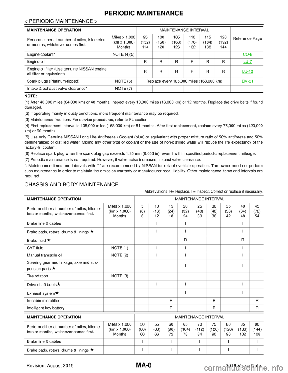
NOTE:
(1) After 40,000 miles (64,000 km) or 48 months, inspect every 10,000 miles (16,000 km) or 12 months. Replace the drive belts if found
damaged.
(2) If operating mainly in dusty conditions, more frequent maintenance may be required.
(3) Maintenance-free item. For service procedures, refer to FL section.
(4) First replacement interval is 105,000 miles (168,000 km) or 84 months. After first replacement, replace every 75,000 miles (120,000
km) or 60 months.
(5) Use only Genuine NISSAN Long Life Antifreeze / Coolant (blue) or equivalent with proper mixture ratio of 50% antifreeze and 50%
demineralized or distilled water. Mixing any other type of coolant or the use of non-distilled water will reduce the life expec tancy of the
factory-fill coolant.
(6) Replace spark plug when the spark plug gap exceeds 1.35 mm (0.053 in), even if within specified periodic replacement mileag e.
(7) Periodic maintenance is not required. However, if valve noise increases, inspect valve clearance.
*: Maintenance items and intervals with “*” are recommended by NISSAN for reli able vehicle operation. The owner need not perform
such maintenance in order to maintain the emission warranty or manufacturer recall liability. Other maintenance items and inter vals are
required.
CHASSIS AND BODY MAINTENANCE
Abbreviations: R= Replace. I = Inspec t. Correct or replace if necessary.
Engine coolant* NOTE (4)(5) CO-8
Engine oil RRRRRRLU-7
Engine oil filter (Use genuine NISSAN engine
oil filter or equivalent) RRRRRR
LU-10
Spark plugs (Platinum-tipped)NOTE (6) Replace every 105,000 miles (168,000 km) EM-21
Intake & exhaust valve clearance*NOTE (7)
MAINTENANCE OPERATION
MAINTENANCE INTERVAL
Reference Page
Perform either at number of miles, kilometers
or months, whichever comes first. Miles x 1,000
(km x 1,000)
Months 95
(152)
11 4 100
(160)
120 105
(168)
126 11 0
(176)
132 11 5
(184)
138 120
(192)
144
MAINTENANCE OPERATION MAINTENANCE INTERVAL
Perform either at number of miles, kilome-
ters or months, whichever comes first. Miles x 1,000
(km x 1,000)
Months 5
(8)
6 10
(16)
12 15
(24)
18 20
(32)
24 25
(40)
30 30
(48)
36 35
(56)
42 40
(64)
48 45
(72)
54
Brake line & cables IIII
Brake pads, rotors, drums & linings IIII
Brake fluid RR
CVT fluid NOTE (1)IIII
Manual transaxle oil NOTE (2)IIII
Steering gear and linkage, axle and sus-
pension parts II
Tire rotation NOTE (3)
Drive shaft boots IIII
Exhaust system II
In-cabin microfilter RRR
Intelligent key battery RRR
MAINTENANCE OPERATION MAINTENANCE INTERVAL
Perform either at number of miles, kilome-
ters or months, whichever comes first. Miles x 1,000
(km x 1,000) Months 50
(80) 60 55
(88) 66 60
(96) 72 65
(104) 78 70
(112) 84 75
(120) 90 80
(128) 96 85
(136) 102 90
(144) 108
Brake line & cables III II
Brake pads, rotors, drums & linings IIIII
Revision: August 2015
2016 Versa Note
cardiagn.com
Page 2328 of 3641
ENGINE MAINTENANCEMA-13
< PERIODIC MAINTENANCE >
C
DE
F
G H
I
J
K L
M B
MA
N
O A
ENGINE MAINTENANCE
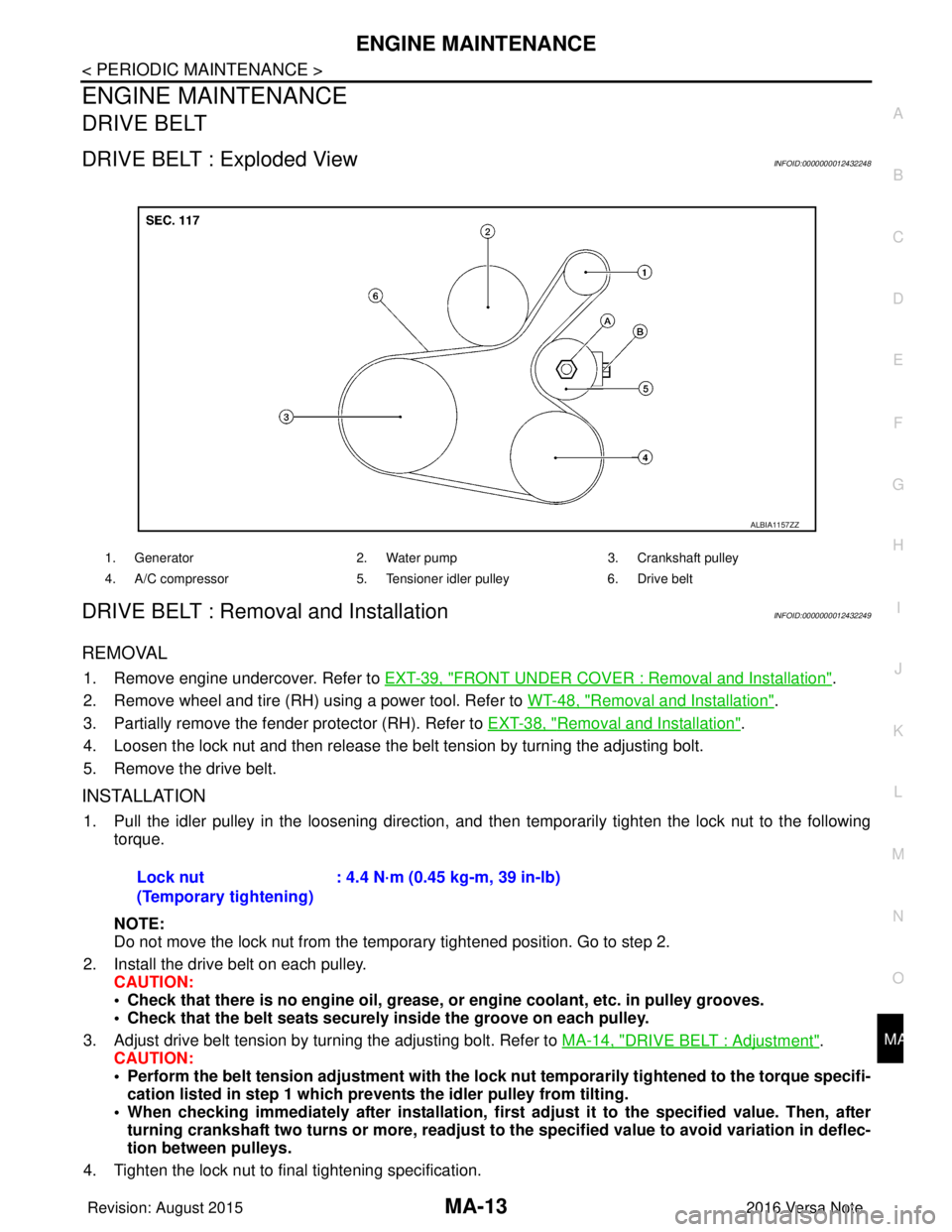
DRIVE BELT
DRIVE BELT : Exploded ViewINFOID:0000000012432248
DRIVE BELT : Removal and InstallationINFOID:0000000012432249
REMOVAL
1. Remove engine undercover. Refer to
EXT-39, "FRONT UNDER COVER : Removal and Installation".
2. Remove wheel and tire (RH) using a power tool. Refer to WT-48, "
Removal and Installation".
3. Partially remove the fender protector (RH). Refer to EXT-38, "
Removal and Installation".
4. Loosen the lock nut and then release the belt tension by turning the adjusting bolt.
5. Remove the drive belt.
INSTALLATION
1. Pull the idler pulley in the loosening direction, and then temporarily tighten the lock nut to the following
torque.
NOTE:
Do not move the lock nut from the temporary tightened position. Go to step 2.
2. Install the drive belt on each pulley. CAUTION:
• Check that there is no engine oil, grease, or engine coolant, etc. in pulley grooves.
• Check that the belt seats securely inside the groove on each pulley.
3. Adjust drive belt tension by turning the adjusting bolt. Refer to MA-14, "
DRIVE BELT : Adjustment".
CAUTION:
• Perform the belt tension adjustment with the lock nut temporarily tightened to the torque specifi-
cation listed in step 1 which preven ts the idler pulley from tilting.
• When checking immediately after in stallation, first adjust it to the specified value. Then, after
turning crankshaft two turns or more, readjust to the specified value to avoid variation in deflec-
tion between pulleys.
4. Tighten the lock nut to final tightening specification.
1. Generator 2. Water pump3. Crankshaft pulley
4. A/C compressor 5. Tensioner idler pulley6. Drive belt
ALBIA1157ZZ
Lock nut
(Temporary tightening): 4.4 N·m (0.45 kg-m, 39 in-lb)
Revision: August 2015
2016 Versa Note
cardiagn.com
Page 2329 of 3641
MA-14
< PERIODIC MAINTENANCE >
ENGINE MAINTENANCE
5. Check that belt tension is within the specification using suitable tool. Refer to EM-116, "Drive Belt".
DRIVE BELT : InspectionINFOID:0000000012432250
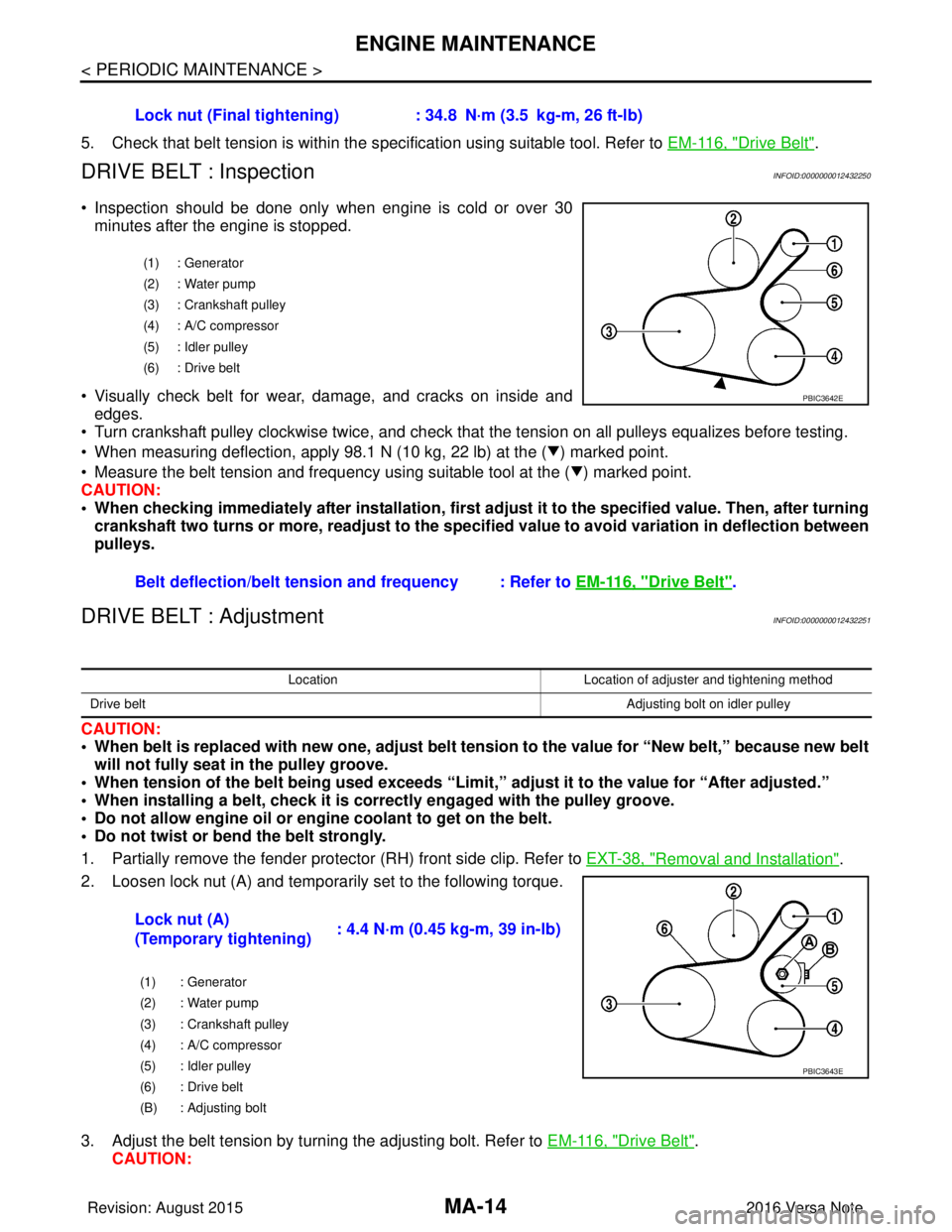
• Inspection should be done only when engine is cold or over 30
minutes after the engine is stopped.
• Visually check belt for wear, damage, and cracks on inside and edges.
• Turn crankshaft pulley clockwise twice, and check that the tension on all pulleys equalizes before testing.
• When measuring deflection, apply 98.1 N (10 kg, 22 lb) at the ( ) marked point.
• Measure the belt tension and frequency using suitable tool at the ( ) marked point.
CAUTION:
• When checking immediately after installation, first ad just it to the specified value. Then, after turning
crankshaft two turns or more, readjust to the speci fied value to avoid variation in deflection between
pulleys.
DRIVE BELT : AdjustmentINFOID:0000000012432251
CAUTION:
• When belt is replaced with new one, adjust belt tension to the value for “New belt,” because new belt will not fully seat in the pulley groove.
• When tension of the belt being used exceeds “Limit,” adjust it to the value for “After adjusted.”
• When installing a belt, check it is co rrectly engaged with the pulley groove.
• Do not allow engine oil or engine coolant to get on the belt.
• Do not twist or bend the belt strongly.
1. Partially remove the fender protector (RH) front side clip. Refer to EXT-38, "
Removal and Installation".
2. Loosen lock nut (A) and temporarily set to the following torque.
3. Adjust the belt tension by turning the adjusting bolt. Refer to EM-116, "
Drive Belt".
CAUTION: Lock nut (Final tightening) :
34.8 N·m (3.5 kg-m, 26 ft-lb)
(1) : Generator
(2) : Water pump
(3) : Crankshaft pulley
(4) : A/C compressor
(5) : Idler pulley
(6) : Drive belt
Belt deflection/belt tension and frequency : Refer to EM-116, "Drive Belt".
PBIC3642E
LocationLocation of adjuster and tightening method
Drive belt Adjusting bolt on idler pulley
Lock nut (A)
(Temporary tightening): 4.4 N·m (0.45 kg-m, 39 in-lb)
(1) : Generator
(2) : Water pump
(3) : Crankshaft pulley
(4) : A/C compressor
(5) : Idler pulley
(6) : Drive belt
(B) : Adjusting bolt
PBIC3643E
Revision: August 2015
2016 Versa Note
cardiagn.com
Page 2330 of 3641
ENGINE MAINTENANCEMA-15
< PERIODIC MAINTENANCE >
C
DE
F
G H
I
J
K L
M B
MA
N
O A
• When checking immediately after in
stallation, first adjust it to the specified value. Then, after
turning crankshaft two turns or more, readjust to the specified value to avoid variation in deflec-
tion between pulleys.
• When the tension adjustment is performed, the lo ck nut should be in the condition at Step 2. If
the tension adjustment is perfo rmed when the lock nut is loosened more than the temporary
tightening, the idler pulley tilts and the co rrect tension adjustment cannot be performed.
4. Tighten the lock nut to final tightening specification.
ENGINE COOLANT
ENGINE COOLANT : InspectionINFOID:0000000012432252
CHECKING COOLING SYSTEM HOSES
Check hoses for the following:
• Improper attachment
• Leaks
•Cracks
• Damage
• Loose connections
• Chafing
• Deterioration
CHECKING RESERVOIR LEVEL
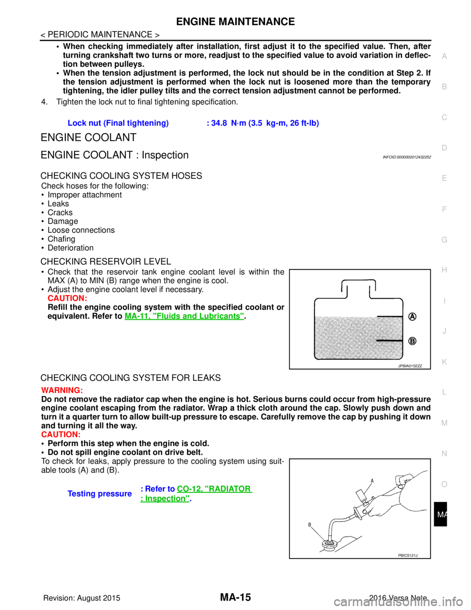
• Check that the reservoir tank engine coolant level is within the MAX (A) to MIN (B) range when the engine is cool.
• Adjust the engine coolant level if necessary. CAUTION:
Refill the engine cooling system with the specified coolant or
equivalent. Refer to MA-11, "
Fluids and Lubricants".
CHECKING COOLING SYSTEM FOR LEAKS
WARNING:
Do not remove the radiator cap when the engine is hot. Serious burns could occur from high-pressure
engine coolant escaping from the radiator. Wrap a thick cloth around the cap. Slowly push down and
turn it a quarter turn to allow built-up pressure to escape. Carefully remove the cap by pushing it down
and turning it all the way.
CAUTION:
• Perform this step when the engine is cold.
• Do not spill engine coolant on drive belt.
To check for leaks, apply pressure to the cooling system using suit-
able tools (A) and (B). Lock nut (Final tightening) :
34.8 N·m (3.5 kg-m, 26 ft-lb)
JPBIA0102ZZ
Testing pressure: Refer to CO-12, "RADIATOR
: Inspection".
PBIC5121J
Revision: August 2015
2016 Versa Note
cardiagn.com
Page 2331 of 3641
MA-16
< PERIODIC MAINTENANCE >
ENGINE MAINTENANCE
ENGINE COOLANT : Draining Engine Coolant
INFOID:0000000012432253
WARNING:
Do not remove the radiator cap when the engine is hot. Serious burns could occur from high-pressure
engine coolant escaping from the radiator. Wrap a th ick cloth around the cap. Slowly push down and
turn it a quarter turn to allow built-up pressure to escape. Carefully remove the cap by pushing it down
and turning it all the way.
1. Remove front under cover. Refer to EXT-39, "
FRONT UNDER COVER : Removal and Installation".
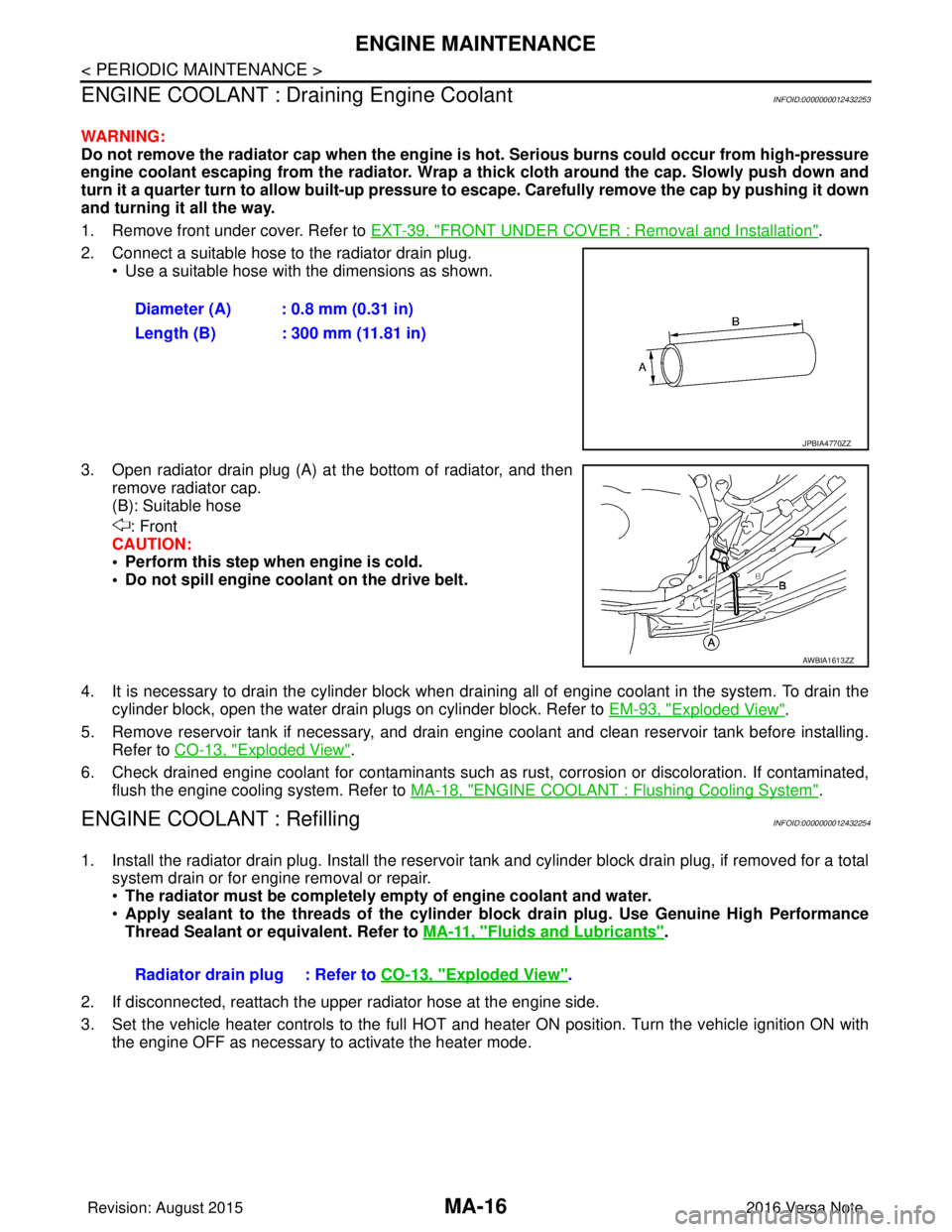
2. Connect a suitable hose to the radiator drain plug. • Use a suitable hose with the dimensions as shown.
3. Open radiator drain plug (A) at the bottom of radiator, and then remove radiator cap.
(B): Suitable hose
: Front
CAUTION:
• Perform this step when engine is cold.
• Do not spill engine coolant on the drive belt.
4. It is necessary to drain the cylinder block when drai ning all of engine coolant in the system. To drain the
cylinder block, open the water drain plugs on cylinder block. Refer to EM-93, "
Exploded View".
5. Remove reservoir tank if necessary, and drain engine coolant and clean reservoir tank before installing. Refer to CO-13, "
Exploded View".
6. Check drained engine coolant for contaminants such as rust, corrosion or discoloration. If contaminated, flush the engine cooling system. Refer to MA-18, "
ENGINE COOLANT : Flushing Cooling System".
ENGINE COOLANT : RefillingINFOID:0000000012432254
1. Install the radiator drain plug. Install the reservoir tank and cylinder block drain plug, if removed for a total
system drain or for engine removal or repair.
• The radiator must be completely empty of engine coolant and water.
• Apply sealant to the threads of the cylinder block drain plug. Use Genuine High Performance
Thread Sealant or equivalent. Refer to MA-11, "
Fluids and Lubricants".
2. If disconnected, reattach the upper radiator hose at the engine side.
3. Set the vehicle heater controls to the full HOT and heat er ON position. Turn the vehicle ignition ON with
the engine OFF as necessary to activate the heater mode. Diameter (A) : 0.8 mm (0.31 in)
Length (B) : 300 mm (11.81 in)
JPBIA4770ZZ
AWBIA1613ZZ
Radiator drain plug : Refer to
CO-13, "Exploded View".
Revision: August 2015 2016 Versa Note
cardiagn.com
Page 2337 of 3641
MA-22
< PERIODIC MAINTENANCE >
ENGINE MAINTENANCE
CAUTION:
• The refill capacity depends on the engine oil temperature and drain time. Use these specifica-
tions for reference only.
• Always use oil level gauge to determine the pr oper amount of engine oil in the engine.
3. Warm up engine and check area around drain plug and oil filter for engine oil leaks. Repair as necessary.
4. Stop engine and wait for 10 minutes.
5. Check the engine oil level. Refer to MA-20, "
ENGINE OIL : Inspection".
OIL FILTER
OIL FILTER : Removal and InstallationINFOID:0000000012432262
REMOVAL
1. Drain engine oil. Refer to MA-21, "ENGINE OIL : Draining".
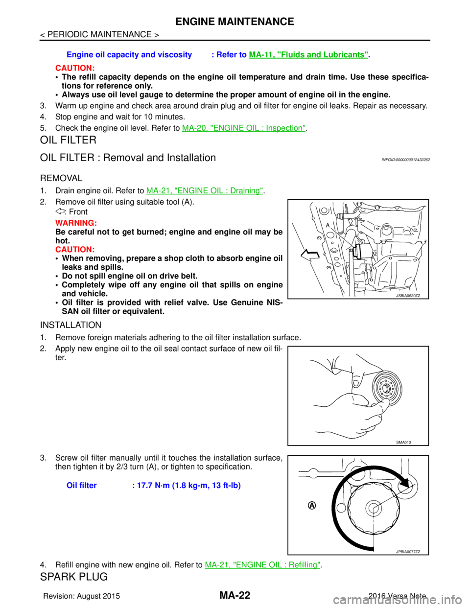
2. Remove oil filter using suitable tool (A). : Front
WARNING:
Be careful not to get burned; engine and engine oil may be
hot.
CAUTION:
• When removing, prepare a shop cloth to absorb engine oil leaks and spills.
• Do not spill engine oil on drive belt.
• Completely wipe off any engine oil that spills on engine
and vehicle.
• Oil filter is provided with relief valve. Use Genuine NIS- SAN oil filter or equivalent.
INSTALLATION
1. Remove foreign materials adhering to the oil filter installation surface.
2. Apply new engine oil to the oil seal contact surface of new oil fil- ter.
3. Screw oil filter manually until it touches the installation surface,
then tighten it by 2/3 turn (A), or tighten to specification.
4. Refill engine with new engine oil. Refer to MA-21, "
ENGINE OIL : Refilling".
SPARK PLUG
Engine oil capacity and viscosity : Refer to MA-11, "Fluids and Lubricants".
JSBIA0620ZZ
SMA010
Oil filter : 17.7 N·m (1.8 kg-m, 13 ft-lb)
JPBIA0077ZZ
Revision: August 2015 2016 Versa Note
cardiagn.com
Page 2358 of 3641
CHASSIS AND BODY MAINTENANCEMA-43
< PERIODIC MAINTENANCE >
C
DE
F
G H
I
J
K L
M B
MA
N
O A
SEAT BELT, BUCKLES, RETRAC
TORS, ANCHORS AND ADJUSTERS
SEAT BELT, BUCKLES, RETRACTORS, ANCHORS AND ADJUSTERS : Inspection
INFOID:0000000012432297
Check the seat belt buckles, webbing, retractors, anc hors and adjusters. Replace any seat belt assembly as
necessary. Refer to SB-5, "
Inspection".
• Check the seat belt anchors for loose bolts, damage, or excessive wear.
• Check the seat belt webbing for any damage, cuts, fraying, or excessive wear.
• Check the retractor for smooth operation.
• Check the function of the buckles by inserting the seat belt tongue and checking for proper engagement of
the buckle and press the button on the buckle to c heck for proper release of the seat belt tongue.
CAUTION:
• After any collision, inspect al l seat belt assemblies, including retractors and other attached compo-
nents, such as the guide rail set. NISSAN recomme nds replacing all seat belt assemblies in use dur-
ing a collision, unless they are not damaged an d are inspected to confirm they are operating
properly after a minor collision.
Also inspect all seat belt assemblies that are not in use during a collision, and replace any compo-
nents if damaged or not operating properly. The seat belt pre-tensioner should be replaced even if
the seat belts are not in use during a frontal collision where the driver and passenger air bags have
been deployed.
• If any component of the seat belt assembly is susp ected of being damaged or not operating prop-
erly, do not repair the component. Replace the components as an assembly.
• If the seat belt webbing is cut, frayed, or damaged then replace the seat belt assembly.
• Do not lubricate the seat belt buckle or tongue.
• When replacing any seat belt assembly alw ays use a Genuine NISSAN seat belt assembly.
Revision: August 2015 2016 Versa Note
cardiagn.com
Page 2359 of 3641
MWI
MWI-1
DRIVER INFORMATION & MULTIMEDIA
C
DE
F
G H
I
J
K L
M B
SECTION MWI
A
O P
CONTENTS
METER, WARNING LAMP & INDICATOR
TYPE A
HOW TO USE THIS MANU AL ......................
5
APPLICATION NOTICE ................................. .....5
Information .......................................................... ......5
PRECAUTION ...............................................6
PRECAUTIONS .............................................. .....6
Precaution for Supplemental Restraint System
(SRS) "AIR BAG" and "SEAT BELT PRE-TEN-
SIONER" ............................................................. ......
6
PREPARATION ............................................7
PREPARATION .............................................. .....7
Commercial Service Tools .................................. ......7
SYSTEM DESCRIPTION ..............................8
COMPONENT PARTS ................................... .....8
METER SYSTEM .........................................................8
METER SYSTEM : Compo nent Parts Location ........8
METER SYSTEM : Combinat ion Meter ....................9
SYSTEM ......................................................... ....10
METER SYSTEM .......................................................10
METER SYSTEM : System Description ..................10
METER SYSTEM : Fail-safe ...................................11
SPEEDOMETER ................ ........................................12
SPEEDOMETER : System Description ............... ....12
TACHOMETER ...................................................... ....12
TACHOMETER : System Description .....................12
SHIFT POSITION INDICATOR .............................. ....12
SHIFT POSITION INDICATOR : System Descrip-
tion ...................................................................... ....
13
OIL PRESSURE WARNING LAMP ...........................13
OIL PRESSURE WARNING LAMP : System De-
scription ............................................................... ....
13
METER ILLUMINATION CONTROL ..................... ....13
METER ILLUMINATION CONTROL : System De-
scription ...................................................................
13
INFORMATION DISPLAY ...................................... ....14
INFORMATION DISPLAY : System Description .....14
OPERATION .....................................................16
Switch Name and Function ......................................16
DIAGNOSIS SYSTEM (COMBINATION
METER) .............................................................
17
On Board Diagnosis Function ..................................17
CONSULT Function (METER/M&A) ........................18
ECU DIAGNOSIS INFORMATION ..............21
COMBINATION METER ...................................21
Reference Value .................................................. ....21
Fail-safe ...................................................................23
DTC Index ...............................................................24
BCM (BODY CONTROL MODULE) .................25
List of ECU Reference .............................................25
WIRING DIAGRAM ......................................26
METER SYSTEM ..............................................26
Wiring Diagram .................................................... ....26
BASIC INSPECTION ...................................37
DIAGNOSIS AND REPAIR WORK FLOW .......37
Work Flow ............................................................ ....37
DTC/CIRCUIT DIAGNOSIS .........................38
U1000 CAN COMM CIRCUIT ...........................38
DTC Logic ............................................................ ....38
Diagnosis Procedure ..............................................38
Revision: August 2015 2016 Versa Note
cardiagn.com