2016 NISSAN NOTE belt
[x] Cancel search: beltPage 1770 of 3641
PRECAUTIONSEXT-3
< PRECAUTION >
C
DE
F
G H
I
J
L
M A
B
EXT
N
O P
PRECAUTION
PRECAUTIONS
Precaution for Supplemental Restraint System (SRS) "AIR BAG" and "SEAT BELT
PRE-TENSIONER"
INFOID:0000000012432151
The Supplemental Restraint System such as “AIR BAG” and “SEAT BELT PRE-TENSIONER”, used along
with a front seat belt, helps to reduce the risk or severi ty of injury to the driver and front passenger for certain
types of collision. Information necessary to service the system safely is included in the SR and SB section of
this Service Manual.
WARNING:
• To avoid rendering the SRS inoper ative, which could increase the risk of personal injury or death in
the event of a collision which would result in air bag inflation, all maintenance must be performed by
an authorized NISSAN/INFINITI dealer.
• Improper maintenance, including in correct removal and installation of the SRS, can lead to personal
injury caused by unintentional act ivation of the system. For removal of Spiral Cable and Air Bag
Module, see the SR section.
• Do not use electrical test equipm ent on any circuit related to the SRS unless instructed to in this
Service Manual. SRS wiring harnesses can be identi fied by yellow and/or orange harnesses or har-
ness connectors.
PRECAUTIONS WHEN USING POWER TOOLS (AIR OR ELECTRIC) AND HAMMERS
WARNING:
• When working near the Airbag Diagnosis Sensor Un it or other Airbag System sensors with the Igni-
tion ON or engine running, DO NOT use air or el ectric power tools or strike near the sensor(s) with a
hammer. Heavy vibration could activate the sensor( s) and deploy the air bag(s), possibly causing
serious injury.
• When using air or electric power tools or hammers, always switch the Ignition OFF, disconnect the
battery and wait at least three mi nutes before performing any service.
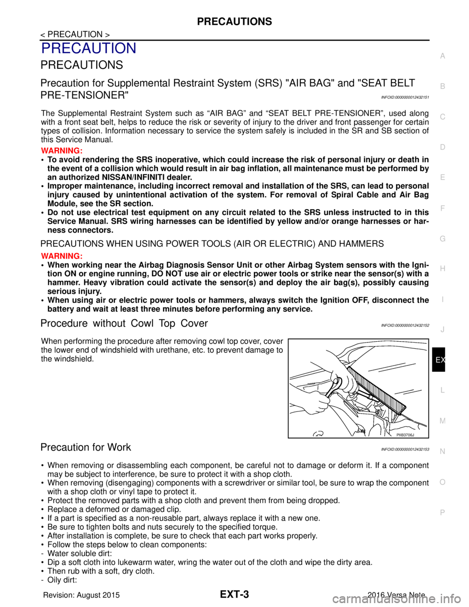
Procedure without Cowl Top CoverINFOID:0000000012432152
When performing the procedure after removing cowl top cover, cover
the lower end of windshield with urethane, etc. to prevent damage to
the windshield.
Precaution for WorkINFOID:0000000012432153
• When removing or disassembling each component, be ca reful not to damage or deform it. If a component
may be subject to interference, be sure to protect it with a shop cloth.
• When removing (disengaging) components with a screwdriver or similar tool, be sure to wrap the component with a shop cloth or vinyl tape to protect it.
• Protect the removed parts with a shop cloth and prevent them from being dropped.
• Replace a deformed or damaged clip.
• If a part is specified as a non-reusabl e part, always replace it with a new one.
• Be sure to tighten bolts and nuts securely to the specified torque.
• After installation is complete, be sure to check that each part works properly.
• Follow the steps below to clean components:
- Water soluble dirt:
• Dip a soft cloth into lukewarm water, wring the water out of the cloth and wipe the dirty area.
• Then rub with a soft, dry cloth.
-Oily dirt:
PIIB3706J
Revision: August 2015 2016 Versa Note
cardiagn.com
Page 1818 of 3641
FAX-1
TRANSMISSION & DRIVELINE
CEF
G H
I
J
K L
M
SECTION FA X
A
B
FA X
N
O P
CONTENTS
FRONT AXLE
PRECAUTION ....... ........................................2
PRECAUTIONS .............................................. .....2
Precaution for Supplemental Restraint System
(SRS) "AIR BAG" and "SEAT BELT PRE-TEN-
SIONER" ............................................................. ......
2
Precaution for Drive Shaft .........................................2
Precautions for Wheel Hub and Knuckle ..................2
PREPARATION ............................................3
PREPARATION .............................................. .....3
Special Service Tools .......................................... ......3
Commercial Service Tools ........................................4
SYMPTOM DIAGNOSIS ...............................6
NOISE, VIBRATION AND HARSHNESS
(NVH) TROUBLESHOOTING ........................ .....
6
NVH Troubleshooting Chart ................................ ......6
PERIODIC MAINTENANCE ..........................7
FRONT WHEEL HUB AND KNUCKLE ......... .....7
Inspection ............................................................ ......7
FRONT DRIVE SHAFT ........................................8
Inspection ............................................................ ......8
REMOVAL AND INSTALLATION ................9
FRONT WHEEL HUB AND KNUCKLE ......... .....9
Exploded View ..................................................... .....9
Removal and Installation ..........................................9
Disassembly and Assembly .....................................11
Inspection ................................................................13
FRONT DRIVE SHAFT BOOT ..........................14
Exploded View .........................................................14
WHEEL SIDE ......................................................... ....14
WHEEL SIDE : Removal and Installation ................15
TRANSAXLE SIDE ................................................ ....18
TRANSAXLE SIDE : Removal and Installation .......18
Inspection ............................................................ ....18
FRONT DRIVE SHAFT .....................................19
Exploded View .........................................................19
Removal and Installation .........................................19
UNIT DISASSEMBLY AND ASSEMBLY ....21
FRONT DRIVE SHAFT .....................................21
Exploded View ..................................................... ....21
Disassembly and Assembly .....................................22
SERVICE DATA AND SPECIFICATIONS
(SDS) ............... .......................................... ...
27
SERVICE DATA AND SPECIFICATIONS
(SDS) .................................................................
27
Wheel Bearing ..................................................... ....27
Drive Shaft ...............................................................27
Revision: August 2015 2016 Versa Note
cardiagn.com
Page 1819 of 3641
FAX-2
< PRECAUTION >
PRECAUTIONS
PRECAUTION
PRECAUTIONS
Precaution for Supplemental Restraint System (SRS) "AIR BAG" and "SEAT BELT
PRE-TENSIONER"
INFOID:0000000012431882
The Supplemental Restraint System such as “A IR BAG” and “SEAT BELT PRE-TENSIONER”, used along
with a front seat belt, helps to reduce the risk or severity of injury to the driver and front passenger for certain
types of collision. Information necessary to service the system safely is included in the SR and SB section of
this Service Manual.
WARNING:
• To avoid rendering the SRS inopera tive, which could increase the risk of personal injury or death in
the event of a collision which would result in air bag inflation, all maintenance must be performed by
an authorized NISSAN/INFINITI dealer.
• Improper maintenance, including in correct removal and installation of the SRS, can lead to personal
injury caused by unintent ional activation of the system. For re moval of Spiral Cable and Air Bag
Module, see the SR section.
• Do not use electrical test equipmen t on any circuit related to the SRS unless instructed to in this
Service Manual. SRS wiring harn esses can be identified by yellow and/or orange harnesses or har-
ness connectors.
PRECAUTIONS WHEN USING POWER TOOLS (AIR OR ELECTRIC) AND HAMMERS
WARNING:
• When working near the Airbag Diagnosis Sensor Unit or other Airbag System sensors with the Igni-
tion ON or engine running, DO NOT use air or electri c power tools or strike near the sensor(s) with a
hammer. Heavy vibration could activate the sensor( s) and deploy the air bag(s), possibly causing
serious injury.
• When using air or electric power tools or hammers , always switch the Ignition OFF, disconnect the
battery and wait at least three minutes before performing any service.
Precaution for Drive ShaftINFOID:0000000012431883
Observe the following precautions when disassembling and assembling drive shaft.
• Do not disassemble joint sub-assembly because it is non-overhaul parts.
• Perform work in a location which is as dust-free as possible.
• Clean the parts, before disassembling and assembling.
• Prevent the entry of foreign objects dur ing disassembly of the service location.
• Reassemble disassembled parts carefully in the correct order. If work is interrupted, a clean cover must be placed over parts.
• Use paper waste. Fabric shop cloths must not be used because of the danger of lint adhering to parts.
• Clean disassembled parts (except for rubber parts) with kerosene which shall be removed by blowing with air or wiping with paper waste.
Precautions for Wheel Hub and KnuckleINFOID:0000000012431884
Observe the following precautions when assembling wheel hub and knuckle.
• Perform work in a location which is as dust-free as possible.
• Use paper waste. Fabric shop cloths must not be used because of the danger of lint adhering to parts.
• If any of wheel hub, steering knuckle, wheel bearing, and wheel hub lock nut is dropped, it must not be used.
• Always check that the tools used for press-fit work of wheel hub and wheel bearing have no wear and defor- mation so that a pressure can be applied vertically.
Revision: August 2015 2016 Versa Note
cardiagn.com
Page 1846 of 3641
FSU-1
SUSPENSION
C
DF
G H
I
J
K L
M
SECTION FSU
A
B
FSU
N
O PCONTENTS
FRONT SUSPENSION
PRECAUTION ....... ........................................2
PRECAUTIONS .............................................. .....2
Precaution for Supplemental Restraint System
(SRS) "AIR BAG" and "SEAT BELT PRE-TEN-
SIONER" ............................................................. ......
2
Precaution for Procedure without Cowl Top Cover ......2
Precaution for Suspension ........................................2
PREPARATION ............................................3
PREPARATION .............................................. .....3
Special Service Tools .......................................... ......3
Commercial Service Tools ........................................3
SYMPTOM DIAGNOSIS ...............................5
NOISE, VIBRATION AND HARSHNESS
(NVH) TROUBLESHOOTING ........................ .....
5
NVH Troubleshooting Chart ................................ ......5
PERIODIC MAINTENANCE ..........................6
FRONT SUSPENSION ASSEMBLY .............. .....6
Inspection ............................................................ ......6
WHEEL ALIGNMENT ..........................................7
Inspection ............................................................ ......7
Adjustment ................................................................8
REMOVAL AND INSTALLATION ................9
FRONT COIL SPRING AND STRUT ............. .....9
Exploded View .................................................... ......9
Removal and Installation ...........................................9
TRANSVERSE LINK .........................................10
Exploded View ..................................................... ....10
Removal and Installation .........................................10
Inspection ................................................................10
FRONT STABILIZER ........................................12
Exploded View .........................................................12
Removal and Installation .........................................12
Inspection ................................................................13
UNIT REMOVAL AND INSTALLATION ......14
FRONT SUSPENSION MEMBER .....................14
Exploded View ..................................................... ....14
Removal and Installation .........................................14
Inspection ................................................................15
UNIT DISASSEMBLY AND ASSEMBLY ....16
FRONT COIL SPRING AND STRUT ................16
Exploded View ..................................................... ....16
Disassembly and Assembly .....................................16
Inspection ................................................................19
Disposal ...................................................................19
SERVICE DATA AND SPECIFICATIONS
(SDS) ............... .......................................... ...
20
SERVICE DATA AND SPECIFICATIONS
(SDS) .................................................................
20
Wheel Alignment (Unladen*1) ..................................20
Ball Joint .............................................................. ....20
Wheelarch Height (Unladen*) ..................................21
Revision: August 2015 2016 Versa Note
cardiagn.com
Page 1847 of 3641
FSU-2
< PRECAUTION >
PRECAUTIONS
PRECAUTION
PRECAUTIONS
Precaution for Supplemental Restraint System (SRS) "AIR BAG" and "SEAT BELT
PRE-TENSIONER"
INFOID:0000000012430294
The Supplemental Restraint System such as “A IR BAG” and “SEAT BELT PRE-TENSIONER”, used along
with a front seat belt, helps to reduce the risk or severity of injury to the driver and front passenger for certain
types of collision. Information necessary to service the system safely is included in the SR and SB section of
this Service Manual.
WARNING:
• To avoid rendering the SRS inopera tive, which could increase the risk of personal injury or death in
the event of a collision which would result in air bag inflation, all maintenance must be performed by
an authorized NISSAN/INFINITI dealer.
• Improper maintenance, including in correct removal and installation of the SRS, can lead to personal
injury caused by unintent ional activation of the system. For re moval of Spiral Cable and Air Bag
Module, see the SR section.
• Do not use electrical test equipmen t on any circuit related to the SRS unless instructed to in this
Service Manual. SRS wiring harn esses can be identified by yellow and/or orange harnesses or har-
ness connectors.
PRECAUTIONS WHEN USING POWER TOOLS (AIR OR ELECTRIC) AND HAMMERS
WARNING:
• When working near the Airbag Diagnosis Sensor Unit or other Airbag System sensors with the Igni-
tion ON or engine running, DO NOT use air or electri c power tools or strike near the sensor(s) with a
hammer. Heavy vibration could activate the sensor( s) and deploy the air bag(s), possibly causing
serious injury.
• When using air or electric power tools or hammers , always switch the Ignition OFF, disconnect the
battery and wait at least three minutes before performing any service.
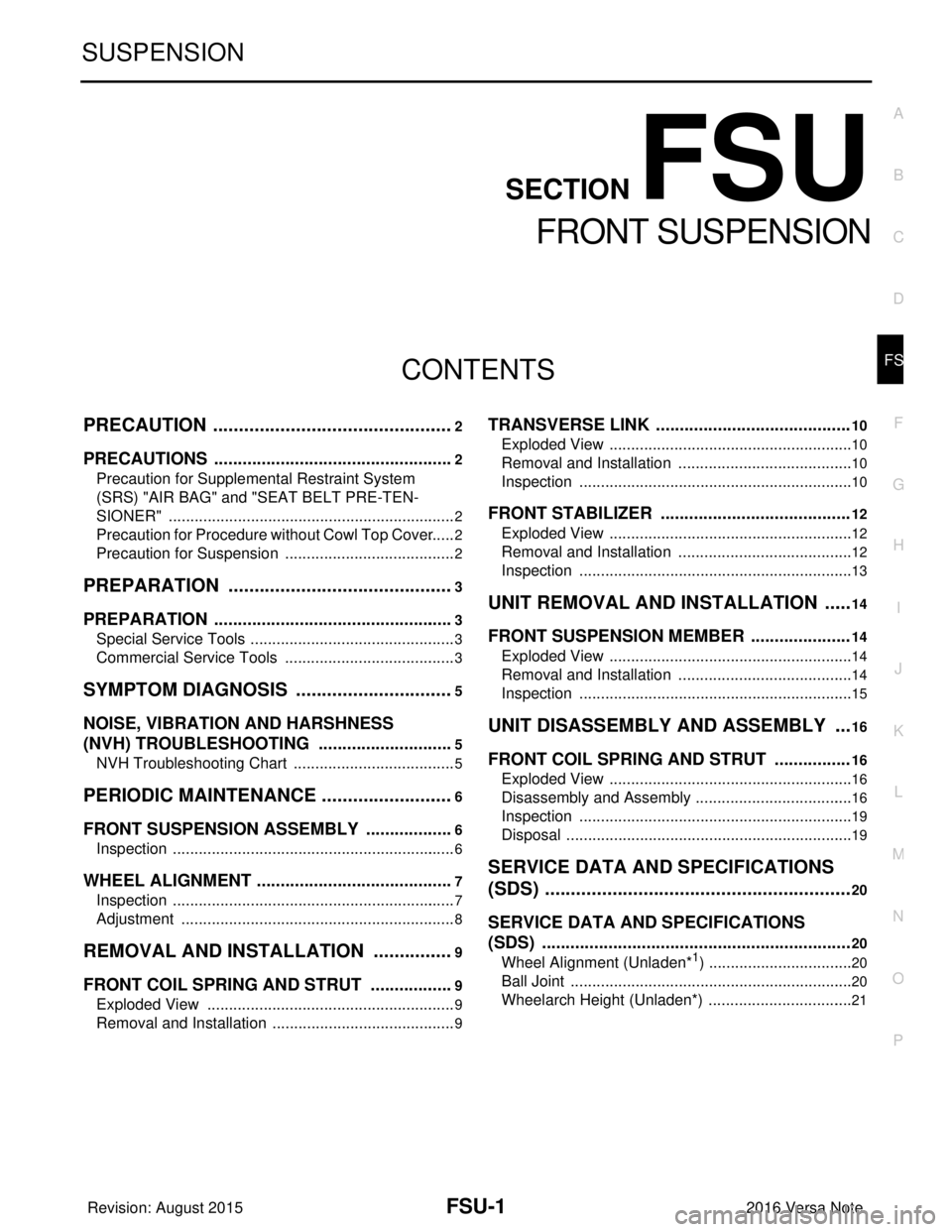
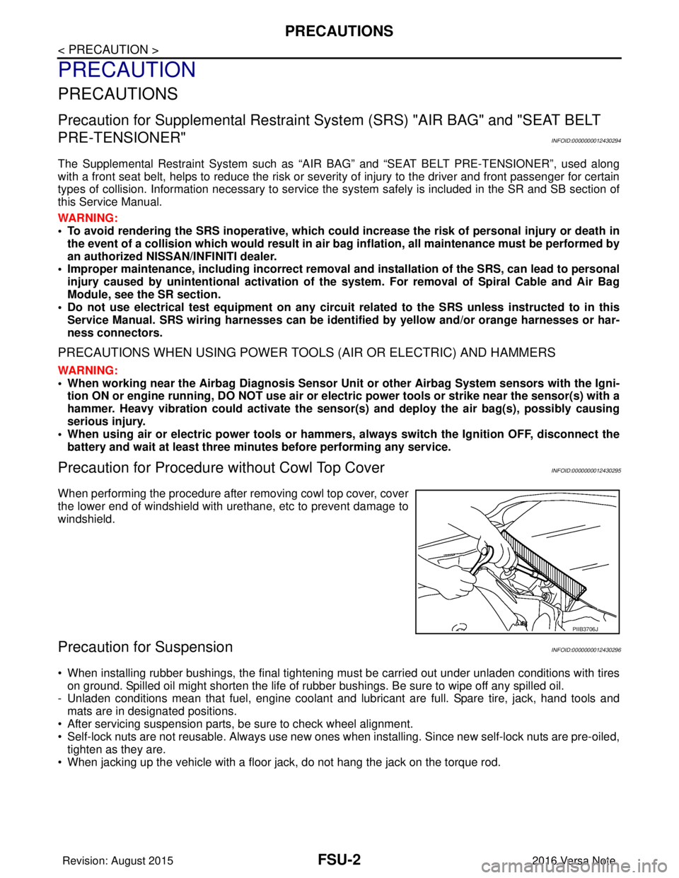
Precaution for Procedure without Cowl Top CoverINFOID:0000000012430295
When performing the procedure after removing cowl top cover, cover
the lower end of windshield with urethane, etc to prevent damage to
windshield.
Precaution for SuspensionINFOID:0000000012430296
• When installing rubber bushings, the final tightening mu st be carried out under unladen conditions with tires
on ground. Spilled oil might shorten the life of rubber bushings. Be sure to wipe off any spilled oil.
- Unladen conditions mean that fuel, engine coolant and lubricant are full. Spare tire, jack, hand tools and mats are in designated positions.
• After servicing suspension parts, be sure to check wheel alignment.
• Self-lock nuts are not reusable. Always use new ones when installing. Since new self-lock nuts are pre-oiled,
tighten as they are.
• When jacking up the vehicle with a floor jack, do not hang the jack on the torque rod.
PIIB3706J
Revision: August 2015 2016 Versa Note
cardiagn.com
Page 1867 of 3641
FL-1
ENGINE
C
DE
F
G H
I
J
K L
M
SECTION FL
A
FL
N
O P
CONTENTS
FUEL SYSTEM
PRECAUTION ....... ........................................2
PRECAUTIONS .............................................. .....2
Precaution for Supplemental Restraint System
(SRS) "AIR BAG" and "SEAT BELT PRE-TEN-
SIONER" ............................................................. ......
2
General Precaution ...................................................2
PREPARATION ............................................4
PREPARATION .............................................. .....4
Special Service Tool ........................................... ......4
Commercial Service Tools ........................................4
PERIODIC MAINTENANCE ..........................5
FUEL SYSTEM ............................................... .....5
Inspection ............................................................ ......5
Quick Connector .......................................................5
REMOVAL AND INSTALLATION ................6
FUEL LEVEL SENSOR UNIT, FUEL FILTER
AND FUEL PUMP ASSEMBLY ..................... .....
6
Exploded View .................................................... ......6
Removal and Installation ...........................................6
Inspection ............................................................ ......9
FUEL TANK ........................................................10
Exploded View .................................................... ....10
Removal and Installation .........................................10
Inspection ............................................................ ....13
EVAP CANISTER ..............................................14
Exploded View ..................................................... ....14
Removal and Installation .........................................14
Inspection ................................................................15
EVAP CANISTER FILTER ................................16
Exploded View .........................................................16
Removal and Installation .........................................16
EVAP CANISTER VENT CONTROL VALVE ...17
Exploded View .........................................................17
Removal and Installation .........................................17
EVAP CONTROL SYSTEM PRESSURE SEN-
SOR ...................................................................
19
Exploded View .........................................................19
Removal and Installation .........................................19
DISASSEMBLY AND ASSEMBLY ..............20
FUEL LEVEL SENSOR UNIT ...........................20
Exploded View ..................................................... ....20
Disassembly and Assembly .....................................20
SERVICE DATA AND SPECIFICATIONS
(SDS) ............... .......................................... ...
22
SERVICE DATA AND SPECIFICATIONS
(SDS) .................................................................
22
Fuel Tank ............................................................. ....22
Revision: August 2015 2016 Versa Note
cardiagn.com
Page 1868 of 3641
FL-2
< PRECAUTION >
PRECAUTIONS
PRECAUTION
PRECAUTIONS
Precaution for Supplemental Restraint System (SRS) "AIR BAG" and "SEAT BELT
PRE-TENSIONER"
INFOID:0000000012432103
The Supplemental Restraint System such as “A IR BAG” and “SEAT BELT PRE-TENSIONER”, used along
with a front seat belt, helps to reduce the risk or severity of injury to the driver and front passenger for certain
types of collision. Information necessary to service the system safely is included in the SR and SB section of
this Service Manual.
WARNING:
• To avoid rendering the SRS inopera tive, which could increase the risk of personal injury or death in
the event of a collision which would result in air bag inflation, all maintenance must be performed by
an authorized NISSAN/INFINITI dealer.
• Improper maintenance, including in correct removal and installation of the SRS, can lead to personal
injury caused by unintent ional activation of the system. For re moval of Spiral Cable and Air Bag
Module, see the SR section.
• Do not use electrical test equipmen t on any circuit related to the SRS unless instructed to in this
Service Manual. SRS wiring harn esses can be identified by yellow and/or orange harnesses or har-
ness connectors.
PRECAUTIONS WHEN USING POWER TOOLS (AIR OR ELECTRIC) AND HAMMERS
WARNING:
• When working near the Airbag Diagnosis Sensor Unit or other Airbag System sensors with the Igni-
tion ON or engine running, DO NOT use air or electri c power tools or strike near the sensor(s) with a
hammer. Heavy vibration could activate the sensor( s) and deploy the air bag(s), possibly causing
serious injury.
• When using air or electric power tools or hammers , always switch the Ignition OFF, disconnect the
battery and wait at least three minutes before performing any service.
General PrecautionINFOID:0000000012432104
WARNING:
When replacing fuel line parts, be sure to observe the following.
• Put a “CAUTION: FLAMMABLE” sign in the work area.
• Be sure to work in a well ventilated area and have a CO
2 fire extinguisher.
• Do not smoke while working on the fuel system. Keep open flames and sparks away from the work
area.
CAUTION:
• Before removing fuel line parts, carry out the following procedures:
- Put drained fuel in an explosi on-proof container and put the lid on securely. Keep the container in
safe area.
- Release fuel pressure from the fuel lines. Refer to EC-1
37, "Work Procedure" .
- Disconnect the battery ground
cable.
• Always replace O-rings and clamps with new ones.
• Do not kink or twist tubes when they are being installed.
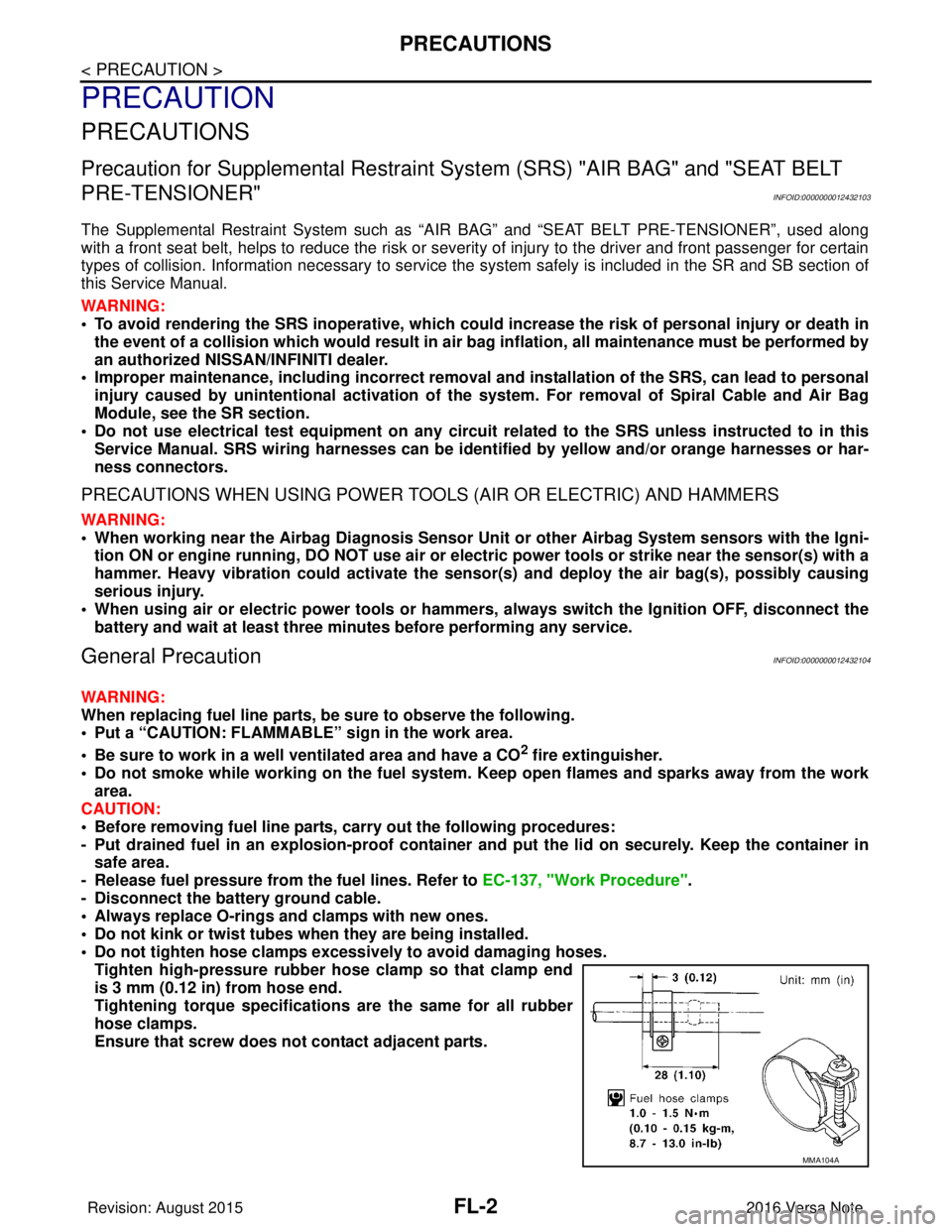
• Do not tighten hose clamps excessi vely to avoid damaging hoses.
Tighten high-pressure rubber hose clamp so that clamp end
is 3 mm (0.12 in) from hose end.
Tightening torque specificati ons are the same for all rubber
hose clamps.
Ensure that screw does not contact adjacent parts.
MMA104A
Revision: August 2015 2016 Versa Note
cardiagn.com
Page 1889 of 3641

GI-1
GENERAL INFORMATION
C
DE
F
G H
I
J
K L
M B
GI
SECTION GI
N
O P
CONTENTS
GENERAL INFORMATION
HOW TO USE THIS MANU AL ......................3
HOW TO USE THIS MANUAL ....................... .....3
Description .......................................................... ......3
Terms ........................................................................3
Units ..........................................................................3
Contents ....................................................................3
Relation between Illustrations and Descriptions .......4
Components ..............................................................4
HOW TO FOLLOW TROUBLE DIAGNOSES .....6
Description ................................................................6
How to Follow Test Groups in Trouble Diagnosis ......6
Key to Symbols Signifying Measurements or Pro-
cedures ............................................................... ......
7
HOW TO READ WIRING DIAGRAMS ................9
Connector Symbols ............................................. ......9
Sample/Wiring Diagram -Example- .........................10
Connector Information .............................................12
ABBREVIATIONS .......................................... ....14
Abbreviation List .................................................. ....14
TIGHTENING TORQUE OF STANDARD
BOLTS ................................................................
19
Description .......................................................... ....19
Tightening Torque Table (New Standard Includ-
ed) ...........................................................................
19
RECOMMENDED CHEMICAL PRODUCTS
AND SEALANTS ................................................
22
Recommended Chemical Products and Sealants ....22
PRECAUTION ..............................................23
PRECAUTIONS .............................................. ....23
Description .......................................................... ....23
Precaution for Supplemental Restraint System
(SRS) "AIR BAG" and "SEAT BELT PRE-TEN-
SIONER" .................................................................
23
Procedures without Cowl Top Cover .......................23
Cautions in Removing Battery Terminal and AV
Control Unit (Models with AV Control Unit) .............
23
General Precautions ............................................ ....24
Three Way Catalyst .................................................25
Fuel ..........................................................................25
Multiport Fuel Injection System or Engine Control
System .....................................................................
26
Hoses ......................................................................26
Engine Oils ..............................................................27
Air Conditioning .......................................................27
LIFTING POINT .................................................28
Special Service Tool ................................................28
Garage Jack and Safety Stand ................................28
2-Pole Lift ................................................................29
Board-on Lift ............................................................30
TOW TRUCK TOWING .....................................31
Tow Truck Towing ...................................................31
Vehicle Recovery (Freeing a Stuck Vehicle) ...........31
VEHICLE INFORMATION ...........................33
IDENTIFICATION INFORMATION ....................33
Model Variation .................................................... ....33
Identification Number ...............................................34
Identification Plate ...................................................35
Engine Serial Number .............................................36
CVT Number ............................................................36
Manual Transaxle Number ......................................36
Dimensions ..............................................................36
Wheels & Tires ........................................................37
BASIC INSPECTION ...................................38
SERVICE INFORMATION FOR ELECTRICAL
INCIDENT ..........................................................
38
Work Flow ............................................................ ....38
Control Units and Electrical Parts ............................38
How to Check Terminal ...........................................39
Intermittent Incident ............................................. ....42
Circuit Inspection .....................................................44
Revision: August 2015 2016 Versa Note
cardiagn.com