2016 NISSAN NOTE low oil pressure
[x] Cancel search: low oil pressurePage 2030 of 3641
PRECAUTIONSHA-5
< PRECAUTION >
C
DE
F
G H
J
K L
M A
B
HA
N
O P
• Expansion valve to evaporator
• Refrigerant pressure sensor to liquid tank
WARNING:
Check that all refrigerant is discharged into the recycling equipment and the pressure in the system is
less than atmospheric pressure. Then gradually loo sen the discharge side hose fitting and remove it.
CAUTION:
Observe the following when replacing or cleaning refrigerant cycle components.
• Store it in the same way as it is when mounted on the vehicle when the compressor is removed. Fail- ure to do so will cause oil to enter the low-pressure chamber.
• Always use a torque wrench and a back-up wrench when connecting tubes.
• Immediately plug all openings to prevent entry of dust and moisture after disconnecting tubes.
• Connect the pipes at the final stag e of the operation when installing an air conditioner in the vehicle.
Do not remove the seal caps of pipes and other comp onents until just before required for connec-
tion.
• Allow components stored in cool areas to warm to working area temperature before removing seal
caps. This prevents condensation from forming inside A/C components.
• Remove moisture thoroughly from the refriger ation system before charging the refrigerant.
• Do not reuse O-rings.
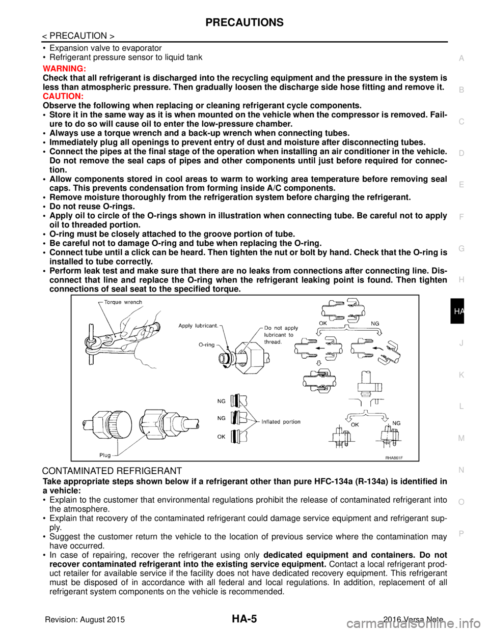
• Apply oil to circle of the O-rings shown in illust ration when connecting tube. Be careful not to apply
oil to threaded portion.
• O-ring must be closely attached to the groove portion of tube.
• Be careful not to damage O-ring and tube when replacing the O-ring.
• Connect tube until a click can be heard. Then tighten the nut or bolt by hand. Check that the O-ring is
installed to tube correctly.
• Perform leak test and make sure that there are no leaks from connections after connecting line. Dis-
connect that line and replace the O-ring when the refrigerant leaking point is found. Then tighten
connections of seal seat to the specified torque.
CONTAMINATED REFRIGERANT
Take appropriate steps shown below if a refrigerant other than pure HFC-134a (R-134a) is identified in
a vehicle:
• Explain to the customer that environmental regulations prohibit the release of contaminated refrigerant into
the atmosphere.
• Explain that recovery of the contaminated refri gerant could damage service equipment and refrigerant sup-
ply.
• Suggest the customer return the vehicle to the locati on of previous service where the contamination may
have occurred.
• In case of repairing, recover the refrigerant using only dedicated equipment and containers. Do not
recover contaminated refrigerant into the existing service equipment. Contact a local refrigerant prod-
uct retailer for available service if the facility does not have dedicated recovery equipment. This refrigerant
must be disposed of in accordance with all federal and local regulations. In addition, replacement of all
refrigerant system components on the vehicle is recommended.
RHA861F
Revision: August 2015 2016 Versa Note
cardiagn.com
Page 2032 of 3641
PRECAUTIONSHA-7
< PRECAUTION >
C
DE
F
G H
J
K L
M A
B
HA
N
O P
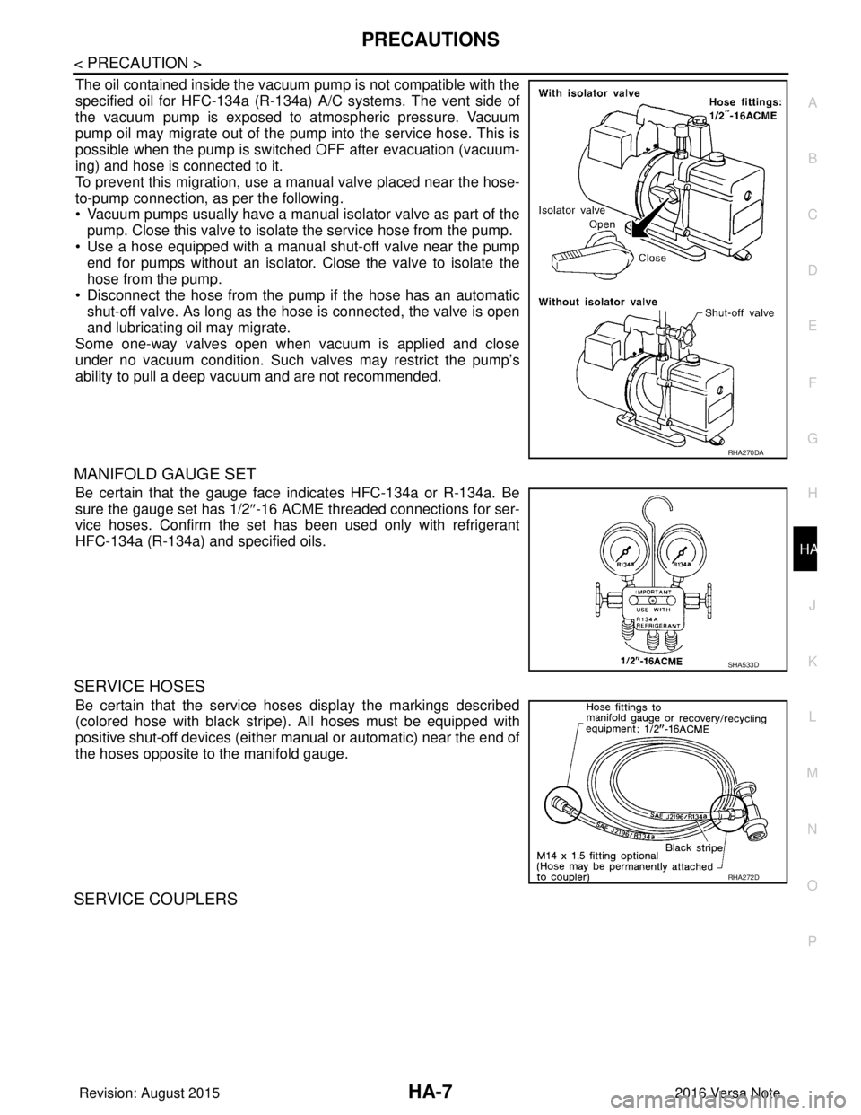
The oil contained inside the vacuum pump is not compatible with the
specified oil for HFC-134a (R-134a) A/C systems. The vent side of
the vacuum pump is exposed to atmospheric pressure. Vacuum
pump oil may migrate out of the pump into the service hose. This is
possible when the pump is switc hed OFF after evacuation (vacuum-
ing) and hose is connected to it.
To prevent this migration, use a manual valve placed near the hose-
to-pump connection, as per the following.
• Vacuum pumps usually have a manual isolator valve as part of the
pump. Close this valve to isolate the service hose from the pump.
• Use a hose equipped with a manual shut-off valve near the pump end for pumps without an isolator. Close the valve to isolate the
hose from the pump.
• Disconnect the hose from the pump if the hose has an automatic shut-off valve. As long as the hose is connected, the valve is open
and lubricating oil may migrate.
Some one-way valves open when vacuum is applied and close
under no vacuum condition. Such valves may restrict the pump’s
ability to pull a deep vacuum and are not recommended.
MANIFOLD GAUGE SET
Be certain that the gauge face indicates HFC-134a or R-134a. Be
sure the gauge set has 1/2 ″-16 ACME threaded connections for ser-
vice hoses. Confirm the set has been used only with refrigerant
HFC-134a (R-134a) and specified oils.
SERVICE HOSES
Be certain that the service hoses display the markings described
(colored hose with black stripe) . All hoses must be equipped with
positive shut-off devices (either manual or automatic) near the end of
the hoses opposite to the manifold gauge.
SERVICE COUPLERS
RHA270DA
SHA533D
RHA272D
Revision: August 2015 2016 Versa Note
cardiagn.com
Page 2045 of 3641
HA-20
< PERIODIC MAINTENANCE >
REFRIGERANT
• Air flow: VENT (ventilation)
• Intake door position: Recirculation
• Temperature setting: Full cold
• Blower speed: Maximum
7. Run the engine at approximately 1,500 rpm for two minutes or more.
8. Stop the engine. Check for refrigerant leaks. Go to step 4. WARNING:
Be careful not to get burned when the engine is hot.
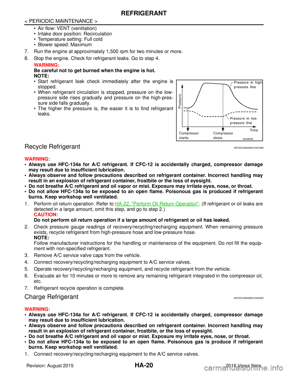
NOTE:
• Start refrigerant leak check immediately after the engine is stopped.
• When refrigerant circulation is stopped, pressure on the low- pressure side rises gradually and pressure on the high-pres-
sure side falls gradually.
• The higher the pressure is, the easier it is to find refrigerant leaks.
Recycle RefrigerantINFOID:0000000012431999
WARNING:
• Always use HFC-134a for A/C refrigerant. If CFC- 12 is accidentally charged, compressor damage
may result due to in sufficient lubrication.
• Always observe and follow precaution s described on refrigerant container. Incorrect handling may
result in an explosion of refrigerant container, frostbite or the loss of eyesight.
• Do not breathe A/C refrigerant and oil vapor or mi st. Exposure may irritate eyes, nose, or throat.
• Do not allow HFC-134a to be exposed to an open flame. Poisonous gas is produced if refrigerant
burns. Keep workshop well ventilated.
1. Perform oil return operation. Refer to HA-22, "
Perform Oil Return Operation". (If refrigerant or oil leaks are
detected in a large amount, omit this step, and go to step 2.)
CAUTION:
Do not perform oil return operation if a la rge amount of refrigerant or oil has leaked.
2. Check pressure gauge readings of recovery/recyc ling/recharging equipment. When remaining pressure
exists, recycle refrigerant from high-pressure hose and low-pressure hose.
NOTE:
Follow manufacturer instructions for the handling or maintenance of the equipment. Do not fill the equip-
ment with non-specified refrigerant.
3. Remove A/C service valve caps from the vehicle.
4. Connect recovery/recycling/recharging equipment to A/C service valves.
5. Operate recovery/recycling/recharging equipm ent, and recycle refrigerant from the vehicle.
6. Evacuate air for 10 minutes or more to remove any remaining refrigerant integrated in the compressor oil,
etc.
7. Refrigerant recycle operation is complete.
Charge RefrigerantINFOID:0000000012432000
WARNING:
• Always use HFC-134a for A/C refrigerant. If CFC- 12 is accidentally charged, compressor damage
may result due to in sufficient lubrication.
• Always observe and follow precaution s described on refrigerant container. Incorrect handling may
result in an explosion of refrigerant co ntainer, frostbite, or the loss of eyesight.
• Do not breathe A/C refrigerant and oil vapor or mi st. Exposure my irritate eyes, nose, or throat.
• Do not allow HFC-134a to be exposed to an open flame. Poisonous gas is produce if refrigerant burns. Keep workshop well ventilated.
1. Connect recovery/recycling/recharging equipment to the A/C service valves.
SHA839E
Revision: August 2015 2016 Versa Note
cardiagn.com
Page 2046 of 3641
REFRIGERANTHA-21
< PERIODIC MAINTENANCE >
C
DE
F
G H
J
K L
M A
B
HA
N
O P
2. Operate recovery/recycling/recharging equipment, and evacuate air from A/C system for 25 minutes or more.
CAUTION:
Evacuate air for 15 minutes or more if parts are replaced.
3. Check the airtightness of A/C system for 25 minutes or more. If pressure raises more than the specified
level, charge A/C system with approximately 200g of refrigerant and check that there are no refrigerant
leaks. Refer to HA-18, "
Leak Test".
CAUTION:
Check the airtightness for 15 minutes or more if parts are replaced.
4. If parts other than the compressor are replaced, fill compressor oil according to parts that are replaced.
Refer to HA-22, "
Oil Adjusting Procedure for Components Replacement Except Compressor".
5. Charge the specified amount of refrigerant into A/C system.
6. Check that the A/C system operates normally.
7. Collect the refrigerant from the high-pressure hos e and low-pressure hose of recovery/recycling/recharg-
ing equipment. Disconnect recovery/recycling/recharging equipment.
8. Install A/C service valve caps.
9. Refrigerant charge is complete.
Revision: August 2015 2016 Versa Note
cardiagn.com
Page 2048 of 3641
OIL
HA-23
< PERIODIC MAINTENANCE >
C
D E
F
G H
J
K L
M A
B
HA
N
O P
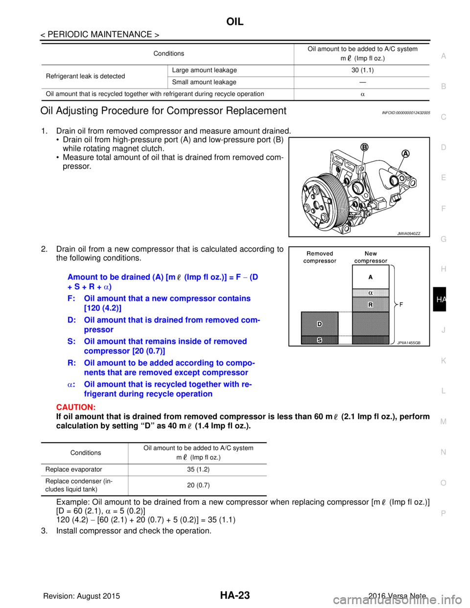
Oil Adjusting Procedure for Compressor ReplacementINFOID:0000000012432005
1. Drain oil from removed compressor and measure amount drained. • Drain oil from high-pressure port (A) and low-pressure port (B)
while rotating magnet clutch.
• Measure total amount of oil that is drained from removed com-
pressor.
2. Drain oil from a new compressor that is calculated according to the following conditions.
CAUTION:
If oil amount that is drained from removed compr essor is less than 60 m (2.1 Imp fl oz.), perform
calculation by setting “D” as 40 m (1.4 Imp fl oz.).
Example: Oil amount to be drained from a new compressor when replacing compressor [m (Imp fl oz.)]
[D = 60 (2.1), α = 5 (0.2)]
120 (4.2) − [60 (2.1) + 20 (0.7) + 5 (0.2)] = 35 (1.1)
3. Install compressor and check the operation.
Refrigerant leak is detected Large amount leakage
30 (1.1)
Small amount leakage —
Oil amount that is recycled together with refrigerant during recycle operation α
Conditions
Oil amount to be added to A/C system
m (Imp fl oz.)
JMIIA0940ZZ
Amount to be drained (A) [m (Imp fl oz.)] = F − (D
+ S + R + α)
F: Oil amount that a new compressor contains [120 (4.2)]
D: Oil amount that is drained from removed com- pressor
S: Oil amount that rema ins inside of removed
compressor [20 (0.7)]
R: Oil amount to be added according to compo- nents that are removed except compressor
α : Oil amount that is recycled together with re-
frigerant during recycle operation
Conditions Oil amount to be added to A/C system
m (Imp fl oz.)
Replace evaporator 35 (1.2)
Replace condenser (in-
cludes liquid tank) 20 (0.7)
JPIIA1455GB
Revision: August 2015
2016 Versa Note
cardiagn.com
Page 2051 of 3641
HA-26
< REMOVAL AND INSTALLATION >
COMPRESSOR
REMOVAL AND INSTALLATION
COMPRESSOR
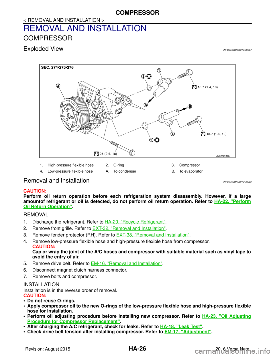
Exploded ViewINFOID:0000000012432007
Removal and InstallationINFOID:0000000012432008
CAUTION:
Perform oil return operation before each refrigeration system disassembly. However, if a large
amountof refrigerant or oil is detected, do not perform oil return operation. Refer to HA-22, "
Perform
Oil Return Operation".
REMOVAL
1. Discharge the refrigerant. Refer to HA-20, "Recycle Refrigerant".
2. Remove front grille. Refer to EXT-32, "
Removal and Installation".
3. Remove fender protector (RH). Refer to EXT-38, "
Removal and Installation".
4. Remove low-pressure flexible hose and high-pressure flexible hose from compressor. CAUTION:
Cap or wrap the joint of the A/C hoses and compr essor with suitable material such as vinyl tape to
avoid the entry of air.
5. Remove drive belt. Refer to EM-16, "
Removal and Installation".
6. Disconnect magnet clutch harness connector.
7. Remove bolts and compressor.
INSTALLATION
Installation is in the reverse order of removal.
CAUTION:
• Do not reuse O-rings.
• Apply compressor oil to the new O-rings of the low-pressure flexible hose an d high-pressure flexible
hose for installation.
• Perform oil adjusting procedure before installing new compressor. Refer to HA-23, "
Oil Adjusting
Procedure for Compressor Replacement".
• After charging the A/C refrig erant, check for leaks. Refer to HA-18, "
Leak Test".
• Check drive belt tension after installing compressor. Refer to EM-17, "
Adjustment".
JMIIA1211GB
1. High-pressure flexible hose 2. O-ring 3. Compressor
4. Low-pressure flexible hose A. To condenser B. To evaporator
Revision: August 2015 2016 Versa Note
cardiagn.com
Page 2053 of 3641
HA-28
< REMOVAL AND INSTALLATION >
COOLER PIPE AND HOSE
COOLER PIPE AND HOSE
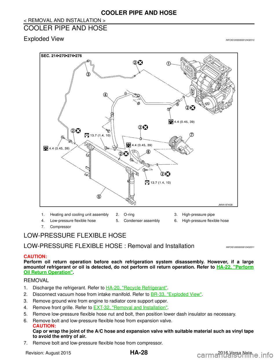
Exploded ViewINFOID:0000000012432010
LOW-PRESSURE FLEXIBLE HOSE
LOW-PRESSURE FLEXIBLE HOSE : Removal and InstallationINFOID:0000000012432011
CAUTION:
Perform oil return operation before each refrigeration system disassembly. However, if a large
amountof refrigerant or oil is detected, do not perform oil return operation. Refer to HA-22, "
Perform
Oil Return Operation".
REMOVAL
1. Discharge the refrigerant. Refer to HA-20, "Recycle Refrigerant".
2. Disconnect vacuum hose from intake manifold. Refer to BR-33, "
Exploded View".
3. Remove ground wire from engine to radiator core support upper.
4. Remove front grille. Refer to EXT-32, "
Removal and Installation".
5. Remove low-pressure flexible hose nut and bolt, then position lower dash insulator as necessary.
6. Remove bolt and low-pressure flexible hose from expansion valve. CAUTION:
Cap or wrap the joint of the A/C hose and expansion valve with suitable material such as vinyl tape
to avoid the entry of air.
7. Remove bolt and low-pressure flexible hose from compressor.
1. Heating and cooling unit assembly 2. O-ring 3. High-pressure pipe
4. Low-pressure flexible hose 5. Condenser assembly 6. High-pressure flexible hose
7. Compressor
JMIIA1874GB
Revision: August 2015 2016 Versa Note
cardiagn.com
Page 2054 of 3641
COOLER PIPE AND HOSEHA-29
< REMOVAL AND INSTALLATION >
C
DE
F
G H
J
K L
M A
B
HA
N
O P
CAUTION:
Cap or wrap the joint of the A/ C hose and compressor with suitable material such as vinyl tape to
avoid the entry of air.
INSTALLATION
Installation is in the reverse order of removal.
CAUTION:
• Do not reuse O-rings.
• Apply compressor oil to new O-rings of low-pressure flexible hose for installation.
• After charging refrigerant, check for leaks. Refer to HA-18, "
Leak Test".
HIGH-PRESSURE FLEXIBLE HOSE
HIGH-PRESSURE FLEXIBLE HOSE : Removal and InstallationINFOID:0000000012432012
CAUTION:
Perform oil return operation before each refrigeration system disassembly. However, if a large
amountof refrigerant or oil is detected, do not perform oil return operation. Refer to HA-22, "
Perform
Oil Return Operation".
REMOVAL
1. Discharge the refrigerant. Refer to HA-20, "Recycle Refrigerant".
2. Remove front grille. Refer to EXT-32, "
Removal and Installation".
3. Remove bolt and high-pressure flexible hose from condenser. CAUTION:
Cap or wrap the joint of the A/C hose and condenser with suitable material such as vinyl tape to
avoid the entry of air.
4. Remove bolt and high-pressure flexible hose from compressor. CAUTION:
Cap or wrap the joint of the A/ C hose and compressor with suitable material such as vinyl tape to
avoid the entry of air.
INSTALLATION
Installation is in the reverse order of removal.
CAUTION:
• Do not reuse O-rings.
• Apply compressor oil to new O-rings of the high-pressure flexible hose for installation.
• After charging refrigerant, check for leaks. Refer to HA-18, "
Leak Test".
HIGH-PRESSURE PIPE
HIGH-PRESSURE PIPE : Removal and InstallationINFOID:0000000012432013
REMOVAL
1. Discharge the refrigerant. Refer to HA-20, "Recycle Refrigerant".
2. Remove radiator core support upper. Refer to DLK-144, "
RADIATOR CORE SUPPORT UPPER :
Removal and Installation".
3. Remove low-pressure flexible hose. Refer to HA-28, "
LOW-PRESSURE FLEXIBLE HOSE : Removal and
Installation".
4. Remove high-pressure flexible hose. Refer to HA-29, "
HIGH-PRESSURE FLEXIBLE HOSE : Removal
and Installation".
5. Disconnect high-pressure pipe from expansion valve. CAUTION:
Cap or wrap the joint of the A/C piping and expan sion valve with suitable material such as vinyl
tape to avoid the entry of air.
6. Remove bolt and high-pressure pipe from condenser. CAUTION:
Cap or wrap the joint of the A/C piping and conden ser with suitable material such as vinyl tape to
avoid the entry of air.
7. Release clips and remove high-pressure pipe from vehicle.
Revision: August 2015 2016 Versa Note
cardiagn.com