2016 NISSAN NOTE low oil pressure
[x] Cancel search: low oil pressurePage 2059 of 3641
HA-34
< REMOVAL AND INSTALLATION >
HEATING AND COOLING UNIT ASSEMBLY
HEATING AND COOLING UNIT ASSEMBLY
HEATING AND COOLING UNIT ASSEMBLY : Removal and InstallationINFOID:0000000012432019
CAUTION:
Perform oil return operation before each refrigeration system disassembly. However, if a large
amountof refrigerant or oil is detected, do not perform oil return operation. Refer to HA-22, "
Perform
Oil Return Operation".
REMOVAL
1. Discharge the refrigerant (if equipped). Refer to HA-20, "Recycle Refrigerant".
2. Drain engine coolant. Refer to CO-8, "
Draining Engine Coolant".
3. Disconnect low-pressure flexible hose from expansion valve (if equipped). Refer to HA-28, "
LOW-PRES-
SURE FLEXIBLE HOSE : Removal and Installation".
CAUTION:
Cap or wrap the joint of the A/C hose and expansion valve with suitable material such as vinyl tape
to avoid the entry of air.
4. Disconnect high-pressure pipe from expansion valve (if equipped). Refer to HA-29, "
HIGH-PRESSURE
PIPE : Removal and Installation".
CAUTION:
Cap or wrap the joint of the A/C piping and expans ion valve with suitable material such as vinyl
tape to avoid the entry of air.
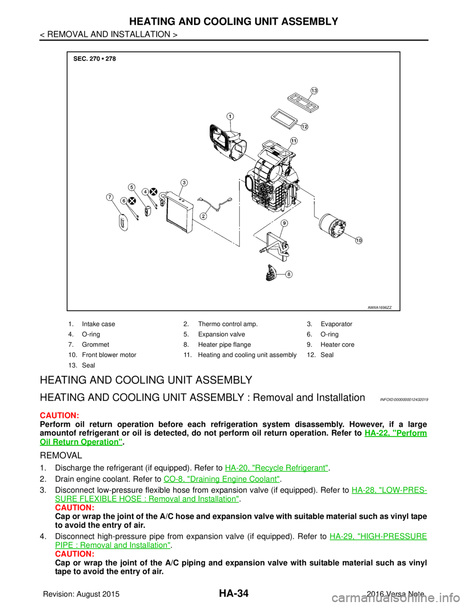
1. Intake case 2. Thermo control amp. 3. Evaporator
4. O-ring 5. Expansion valve 6. O-ring
7. Grommet 8. Heater pipe flange 9. Heater core
10. Front blower motor 11. Heating and cooling unit assembly 12. Seal
13. Seal
AWIIA1696ZZ
Revision: August 2015 2016 Versa Note
cardiagn.com
Page 2060 of 3641
HEATING AND COOLING UNIT ASSEMBLYHA-35
< REMOVAL AND INSTALLATION >
C
DE
F
G H
J
K L
M A
B
HA
N
O P
5. Disconnect heater hoses from heater core.
6. Remove instrument panel assembly. Refer to IP-15, "
Removal and Installation".
7. Disconnect evaporator drain hose from heating and cooling unit assembly.
8. Disconnect harness connectors, grounds, retainers, etc. , and remove bolts required to remove steering
member.
9. Remove steering member and heating and cooling unit assembly.
10. Remove heating and cooling unit assembly from steering member. Refer to HA-33, "
Exploded View".
INSTALLATION
Installation is in the reverse order of removal.
CAUTION:
• Do not reuse O-rings.
• Apply compressor oil to new O-rings of the low-pressure flexible hose and high-pressure pipe for
installation.
• After charging refrigerant, check for leaks. Refer to HA-18, "
Leak Test".
NOTE:
When refilling engine coolant, refer to CO-9, "
Refilling".
HEATER CORE
HEATER CORE : Removal and InstallationINFOID:0000000012432020
REMOVAL
1. Remove the heating and cooling unit assembly. Refer to HA-34, "HEATING AND COOLING UNIT
ASSEMBLY : Removal and Installation".
2. Remove foot duct (LH). Refer to VTL-7, "
FOOT DUCT : Removal and Installation".
3. Remove heater packing.
4. Remove heater pipe flange.
5. Remove heater core.
INSTALLATION
Installation is in the reverse order of removal.
NOTE:
When refilling engine coolant, refer to CO-9, "
Refilling".
EVAPORATOR
EVAPORATOR : Removal and InstallationINFOID:0000000012432021
REMOVAL
1. Remove heating and cooling unit assembly. Refer to HA-34, "HEATING AND COOLING UNIT ASSEM-
BLY : Removal and Installation".
2. Remove foot duct (RH). Refer to VTL-7, "
FOOT DUCT : Removal and Installation".
3. Remove intake case. Refer to HA-33, "
Exploded View".
4. Remove expansion valve. Refer to HA-36, "
EXPANSION VALVE : Removal and Installation".
5. Remove evaporator cover and evaporator assembly.
INSTALLATION
Installation is in the reverse order of removal.
CAUTION:
• Do not reuse O-rings.
• Apply compressor oil to ne w O-rings for installation.
• Perform oil adjusting procedure afte r installing new evaporator. Refer to HA-22, "
Oil Adjusting Pro-
cedure for Components Replacement Except Compressor".
• After charging refrigerant, check for leaks. Refer to HA-18, "
Leak Test".
EXPANSION VALVE
Revision: August 2015 2016 Versa Note
cardiagn.com
Page 2061 of 3641
HA-36
< REMOVAL AND INSTALLATION >
HEATING AND COOLING UNIT ASSEMBLY
EXPANSION VALVE : Removal and Installation
INFOID:0000000012432022
REMOVAL
1. Discharge the refrigerant. Refer to HA-20, "Recycle Refrigerant".
2. Disconnect low-pressure flexible hose from expansion valve. Refer to HA-28, "
LOW-PRESSURE FLEXI-
BLE HOSE : Removal and Installation".
3. Disconnect high-pressure pipe from expansion valve. Refer to HA-29, "
HIGH-PRESSURE PIPE :
Removal and Installation".
4. Remove bolts and expansion valve. CAUTION:
Cap or wrap the joint of the eva porator and expansion valve with su itable material such as vinyl
tape to avoid the entry of air.
INSTALLATION
Installation is in the reverse order of removal.
CAUTION:
• Do not reuse O-rings.
• Apply compressor oil to new O-rings of the low- pressure flexible hose and high-pressure pipe for
installation.
• After charging refrigerant, check for leaks. Refer to HA-18, "
Leak Test".
Revision: August 2015 2016 Versa Note
cardiagn.com
Page 2327 of 3641
MA-12
< PERIODIC MAINTENANCE >
RECOMMENDED FLUIDS AND LUBRICANTS
Engine Oil Recommendation
INFOID:0000000012432246
NISSAN recommends the use of an energy conservi ng oil in order to improve fuel economy.
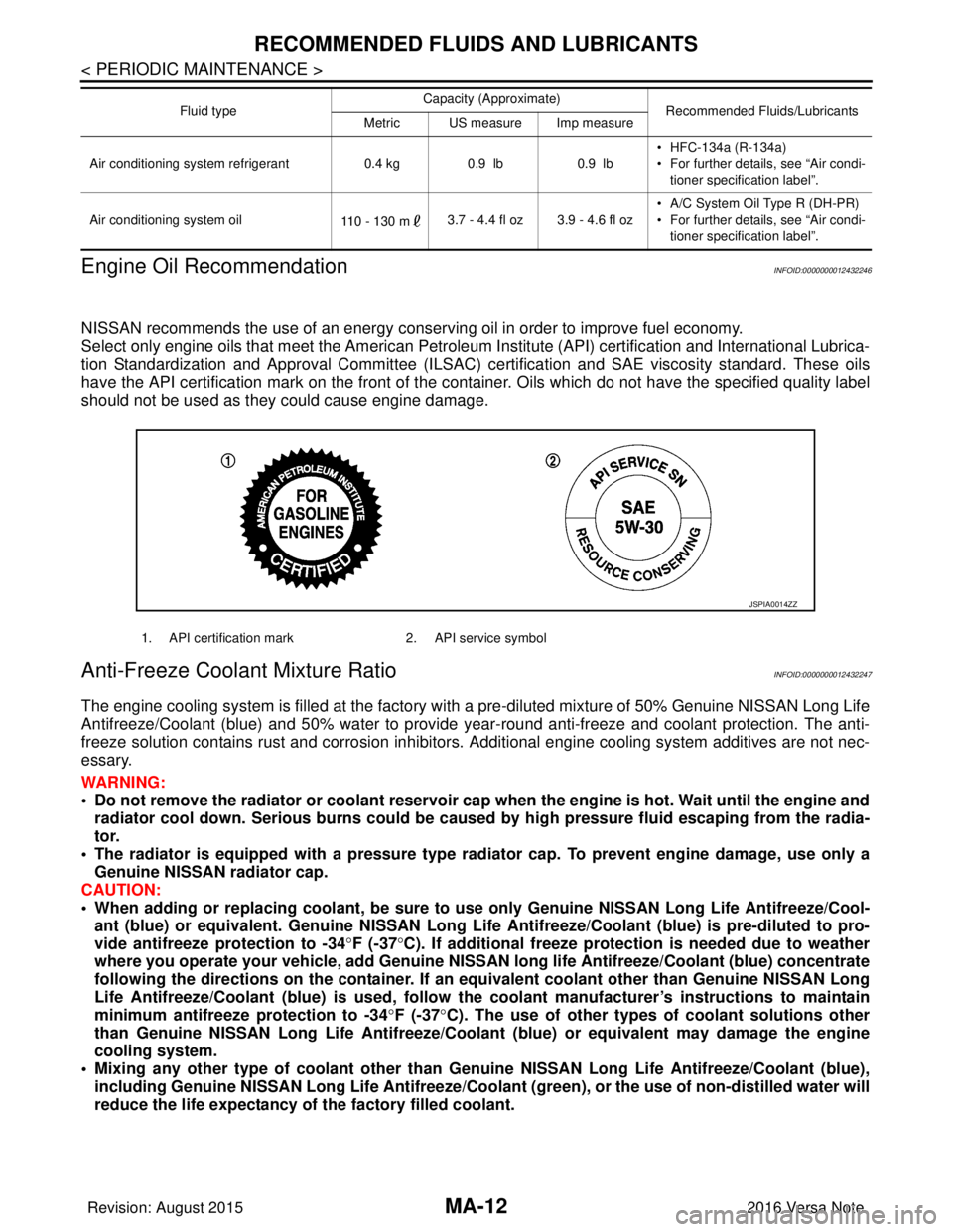
Select only engine oils that meet the American Petroleum Institute (API) certification and International Lubrica-
tion Standardization and Approval Committee (ILSAC) ce rtification and SAE viscosity standard. These oils
have the API certification mark on the front of the container. Oils whic h do not have the specified quality label
should not be used as they could cause engine damage.
Anti-Freeze Coolant Mixture RatioINFOID:0000000012432247
The engine cooling system is filled at the factory with a pre-diluted mixture of 50% Genuine NISSAN Long Life
Antifreeze/Coolant (blue) and 50% water to provide year-round anti-freeze and coolant protection. The anti-
freeze solution contains rust and corrosion inhibitors. Additional engine cooling system additives are not nec-
essary.
WARNING:
• Do not remove the radiator or coolant reservoir cap when the engine is hot. Wait until the engine and radiator cool down. Serious burns could be caused by high pressure fluid escaping from the radia-
tor.
• The radiator is equipped with a pressure type radiator cap. To prevent engine damage, use only a
Genuine NISSAN radiator cap.
CAUTION:
• When adding or replacing coolant, be sure to use only Genuine NISSAN Lo ng Life Antifreeze/Cool-
ant (blue) or equivalent. Genuine NISSAN Long Life Antifreeze/Coolant (blue) is pre-diluted to pro-
vide antifreeze protection to -34 °F (-37 °C). If additional freeze protect ion is needed due to weather
where you operate your vehicle, add Genuine NISSAN long life Antifreeze/Coolant (blue) concentrate
following the directions on the container. If an equivalent coolant other than Genuine NISSAN Long
Life Antifreeze/Coolant (blue) is used, follow the coolant manufact urer’s instructions to maintain
minimum antifreeze protection to -34 °F (-37 °C). The use of other types of coolant solutions other
than Genuine NISSAN Long Life Antifreeze/Coolant (blue) or equivalent may damage the engine
cooling system.
• Mixing any other type of coolant other than Genuine NISSAN Long Life Antifreeze/Coolant (blue),
including Genuine NISSAN Long Life Antifreeze/Coolant (green), or the use of non-distilled water will
reduce the life expectancy of the factory filled coolant.
Air conditioning system refrigerant 0.4 kg0.9 lb 0.9 lb• HFC-134a (R-134a)
• For further details, see “Air condi-
tioner specification label”.
Air conditioning system oil 110 - 130 m3.7 - 4.4 fl oz 3.9 - 4.6 fl oz • A/C System Oil Type R (DH-PR)
• For further details, see “Air condi-
tioner specification label”.
Fluid type
Capacity (Approximate)
Recommended Fluids/Lubricants
Metric US measure Imp measure
1. API certification mark 2. API service symbol
JSPIA0014ZZ
Revision: August 2015 2016 Versa Note
cardiagn.com
Page 2335 of 3641
MA-20
< PERIODIC MAINTENANCE >
ENGINE MAINTENANCE
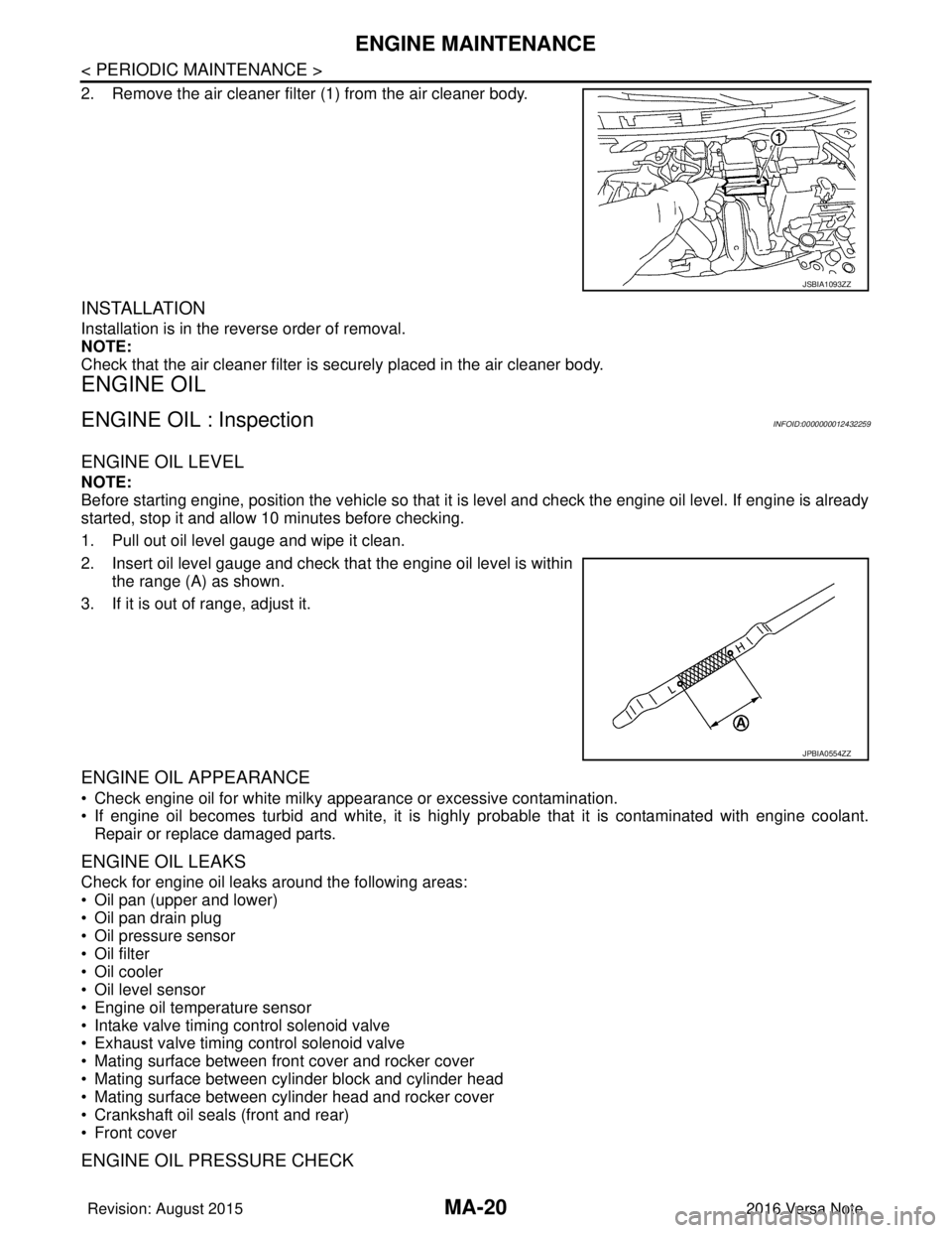
2. Remove the air cleaner filter (1) from the air cleaner body.
INSTALLATION
Installation is in the reverse order of removal.
NOTE:
Check that the air cleaner filter is securely placed in the air cleaner body.
ENGINE OIL
ENGINE OIL : InspectionINFOID:0000000012432259
ENGINE OIL LEVEL
NOTE:
Before starting engine, position the vehicle so that it is level and check the engine oil level. If engine is already
started, stop it and allow 10 minutes before checking.
1. Pull out oil level gauge and wipe it clean.
2. Insert oil level gauge and check that the engine oil level is withinthe range (A) as shown.
3. If it is out of range, adjust it.
ENGINE OIL APPEARANCE
• Check engine oil for white milky appearance or excessive contamination.
• If engine oil becomes turbid and white, it is highl y probable that it is contaminated with engine coolant.
Repair or replace damaged parts.
ENGINE OIL LEAKS
Check for engine oil leaks around the following areas:
• Oil pan (upper and lower)
• Oil pan drain plug
• Oil pressure sensor
• Oil filter
• Oil cooler
• Oil level sensor
• Engine oil temperature sensor
• Intake valve timing control solenoid valve
• Exhaust valve timing control solenoid valve
• Mating surface between front cover and rocker cover
• Mating surface between cylinder block and cylinder head
• Mating surface between cylinder head and rocker cover
• Crankshaft oil seals (front and rear)
• Front cover
ENGINE OIL PRESSURE CHECK
JSBIA1093ZZ
JPBIA0554ZZ
Revision: August 2015 2016 Versa Note
cardiagn.com
Page 2336 of 3641
ENGINE MAINTENANCEMA-21
< PERIODIC MAINTENANCE >
C
DE
F
G H
I
J
K L
M B
MA
N
O A
WARNING:
• Be careful not to burn yoursel
f, as engine oil may be hot.
• When checking engine oil pressure, sh ift selector should be in the "P" (Park) or "N" (Neutral) posi-
tion, and apply parking brake securely.
1. Check engine oil level.
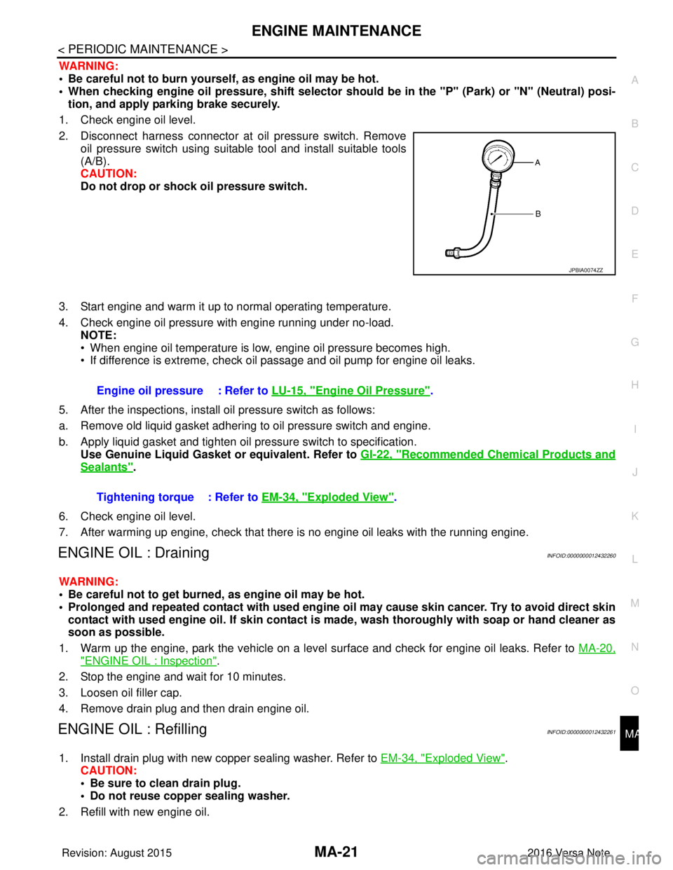
2. Disconnect harness connector at oil pressure switch. Remove oil pressure switch using suitable tool and install suitable tools
(A/B).
CAUTION:
Do not drop or shock oil pressure switch.
3. Start engine and warm it up to normal operating temperature.
4. Check engine oil pressure with engine running under no-load. NOTE:
• When engine oil temperature is low, engine oil pressure becomes high.
• If difference is extreme, check oil passage and oil pump for engine oil leaks.
5. After the inspections, install oil pressure switch as follows:
a. Remove old liquid gasket adhering to oil pressure switch and engine.
b. Apply liquid gasket and tighten oil pressure switch to specification. Use Genuine Liquid Gasket or equivalent. Refer to GI-22, "
Recommended Chemical Products and
Sealants".
6. Check engine oil level.
7. After warming up engine, check that there is no engine oil leaks with the running engine.
ENGINE OIL : DrainingINFOID:0000000012432260
WARNING:
• Be careful not to get burned, as engine oil may be hot.
• Prolonged and repeated contact with used engine oil may cause skin cancer. Try to avoid direct skin
contact with used engine oil. If skin contact is made, wash thorough ly with soap or hand cleaner as
soon as possible.
1. Warm up the engine, park the vehicle on a level surface and check for engine oil leaks. Refer to MA-20,
"ENGINE OIL : Inspection".
2. Stop the engine and wait for 10 minutes.
3. Loosen oil filler cap.
4. Remove drain plug and then drain engine oil.
ENGINE OIL : RefillingINFOID:0000000012432261
1. Install drain plug with new copper sealing washer. Refer to EM-34, "Exploded View".
CAUTION:
• Be sure to clean drain plug.
• Do not reuse copper sealing washer.
2. Refill with new engine oil.
JPBIA0074ZZ
Engine oil pressure : Refer to LU-15, "Engine Oil Pressure".
Tightening torque : Refer to EM-34, "
Exploded View".
Revision: August 2015 2016 Versa Note
cardiagn.com
Page 2346 of 3641
CHASSIS AND BODY MAINTENANCEMA-31
< PERIODIC MAINTENANCE >
C
DE
F
G H
I
J
K L
M B
MA
N
O A
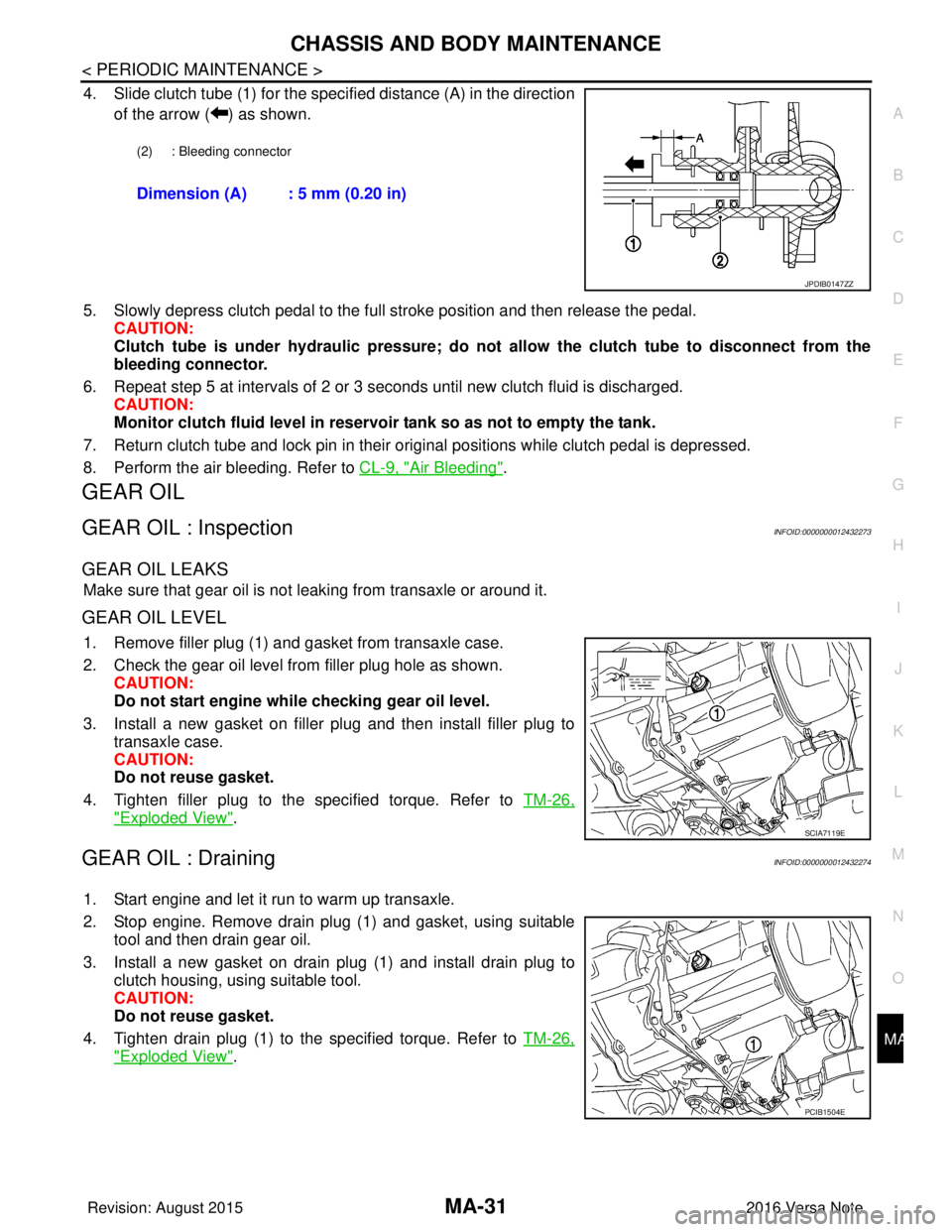
4. Slide clutch tube (1) for the specified distance (A) in the direction
of the arrow ( ) as shown.
5. Slowly depress clutch pedal to the full stroke position and then release the pedal. CAUTION:
Clutch tube is under hydraulic pressure; do not allow the clutch tube to disconnect from the
bleeding connector.
6. Repeat step 5 at intervals of 2 or 3 seconds until new clutch fluid is discharged. CAUTION:
Monitor clutch fluid level in reservoir tank so as not to empty the tank.
7. Return clutch tube and lock pin in their original positions while clutch pedal is depressed.
8. Perform the air bleeding. Refer to CL-9, "
Air Bleeding".
GEAR OIL
GEAR OIL : InspectionINFOID:0000000012432273
GEAR OIL LEAKS
Make sure that gear oil is not leaking from transaxle or around it.
GEAR OIL LEVEL
1. Remove filler plug (1) and gasket from transaxle case.
2. Check the gear oil level from filler plug hole as shown.
CAUTION:
Do not start engine whil e checking gear oil level.
3. Install a new gasket on filler plug and then install filler plug to transaxle case.
CAUTION:
Do not reuse gasket.
4. Tighten filler plug to the specified torque. Refer to TM-26,
"Exploded View".
GEAR OIL : DrainingINFOID:0000000012432274
1. Start engine and let it run to warm up transaxle.
2. Stop engine. Remove drain plug (1) and gasket, using suitable
tool and then drain gear oil.
3. Install a new gasket on drain plug (1) and install drain plug to clutch housing, using suitable tool.
CAUTION:
Do not reuse gasket.
4. Tighten drain plug (1) to the specified torque. Refer to TM-26,
"Exploded View".
(2) : Bleeding connector
Dimension (A) : 5 mm (0.20 in)
JPDIB0147ZZ
SCIA7119E
PCIB1504E
Revision: August 2015 2016 Versa Note
cardiagn.com
Page 2349 of 3641
MA-34
< PERIODIC MAINTENANCE >
CHASSIS AND BODY MAINTENANCE
TIRE ROTATION
• Follow the maintenance schedule for tire rotation service intervals.Refer to MA-7, "
Introduction of Periodic Maintenance".
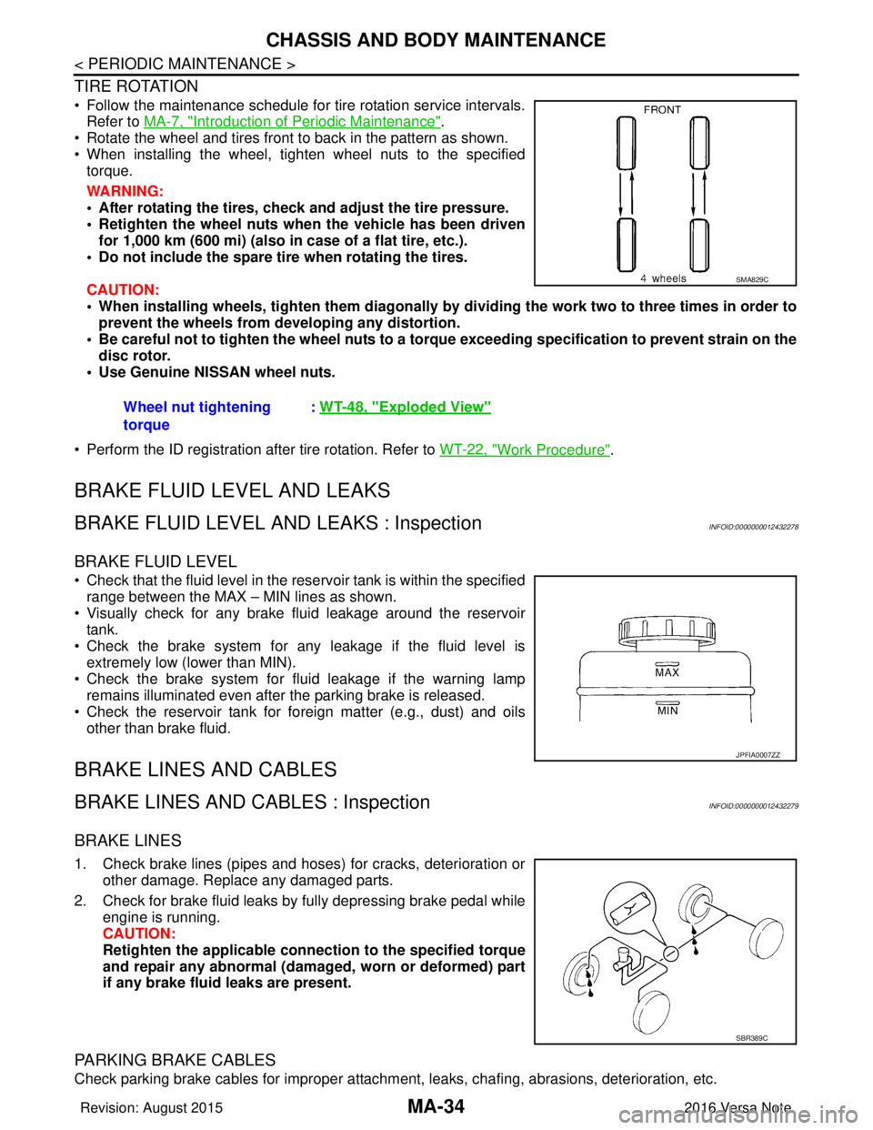
• Rotate the wheel and tires front to back in the pattern as shown.
• When installing the wheel, tighten wheel nuts to the specified torque.
WARNING:
• After rotating the tires, check and adjust the tire pressure.
• Retighten the wheel nuts when the vehicle has been driven
for 1,000 km (600 mi) (also in case of a flat tire, etc.).
• Do not include the spare tire when rotating the tires.
CAUTION:
• When installing wheels, ti ghten them diagonally by dividing the work two to three times in order to
prevent the wheels from d eveloping any distortion.
• Be careful not to tighten the wh eel nuts to a torque exceeding speci fication to prevent strain on the
disc rotor.
• Use Genuine NISSAN wheel nuts.
• Perform the ID registration after tire rotation. Refer to WT-22, "
Work Procedure".
BRAKE FLUID LEVEL AND LEAKS
BRAKE FLUID LEVEL AND LEAKS : InspectionINFOID:0000000012432278
BRAKE FLUID LEVEL
• Check that the fluid level in the reservoir tank is within the specified
range between the MAX – MIN lines as shown.
• Visually check for any brake fluid leakage around the reservoir tank.
• Check the brake system for any leakage if the fluid level is extremely low (lower than MIN).
• Check the brake system for fluid leakage if the warning lamp
remains illuminated even after the parking brake is released.
• Check the reservoir tank for foreign matter (e.g., dust) and oils other than brake fluid.
BRAKE LINES AND CABLES
BRAKE LINES AND CABLES : InspectionINFOID:0000000012432279
BRAKE LINES
1. Check brake lines (pipes and hoses) for cracks, deterioration or other damage. Replace any damaged parts.
2. Check for brake fluid leaks by fully depressing brake pedal while engine is running.
CAUTION:
Retighten the applicable conn ection to the specified torque
and repair any abnormal (damag ed, worn or deformed) part
if any brake fluid leaks are present.
PARKING BRAKE CABLES
Check parking brake cables for improper attachment , leaks, chafing, abrasions, deterioration, etc.
Wheel nut tightening
torque
:
WT-48, "
Exploded View"
SMA829C
JPFIA0007ZZ
SBR389C
Revision: August 2015 2016 Versa Note
cardiagn.com