2016 BMW M4 engine
[x] Cancel search: enginePage 134 of 228

Additionally, look directly to check the traffic
situation and the area around the vehicle and
intervene actively in the corresponding situa‐
tions.◀
Overview
Button in the vehicle
Rear-view camera
Camera
The camera lens is located in the handle strip
of the boot lid. Dirt can impair the quality of the
picture.
Clean the lens of the camera, see page 211.
Switching on/off Automatic activation While the engine is running, engage selector
lever position R.
The image from the rear-view camera is dis‐
played if the system was switched on using the
iDrive.
Automatic switching off when moving
forwards
The system switches off when a certain dis‐
tance or speed is exceeded.
Switch the system back on if necessary.
Switching on/off manually Press the button.▷On: LED is illuminated.▷Off: LED turns off.
PDC is displayed on the Control Display.
Switching the view via iDrive With activated PDC or Top View switched on:
"Rear view camera"
The image from the rear-view camera is dis‐
played.
Display on the Control Display
Operating requirements
▷The rear-view camera is switched on.▷The boot lid is completely closed.
Activating assistance functions
A number of assistance functions can be ac‐
tive simultaneously.
▷Parking aid lines.
"Parking guidance lines"
Driving lane and turning circle lines are dis‐
played.
▷Obstacle marking.
"Obstacle marking"
Spatially shaped markings are displayed.
Seite 134ControlsDriving comfort134
Online Edition for Part no. 01 40 2 964 013 - VI/15
Page 138 of 228

Overview
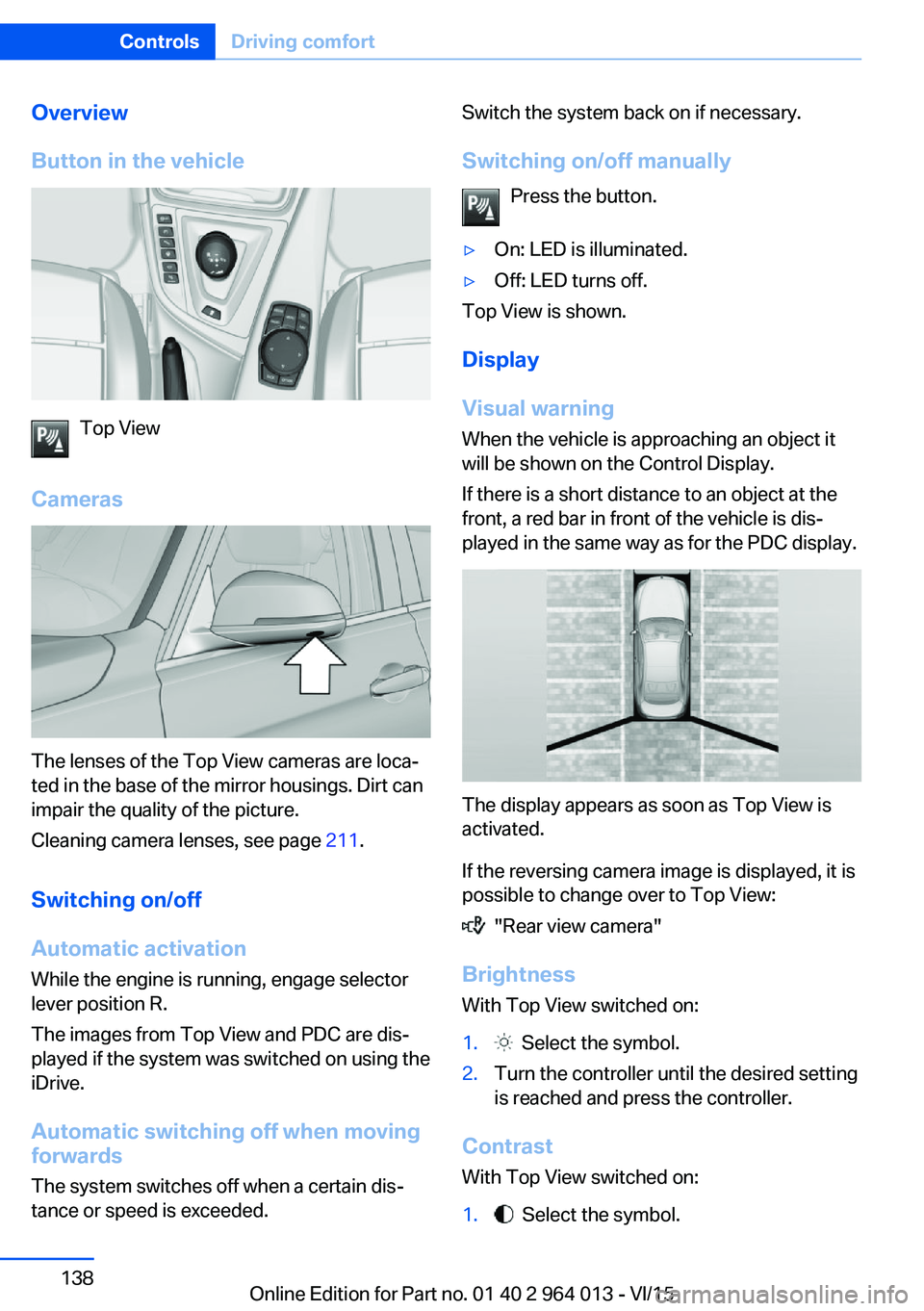
Button in the vehicle
Top View
Cameras
The lenses of the Top View cameras are loca‐
ted in the base of the mirror housings. Dirt can
impair the quality of the picture.
Cleaning camera lenses, see page 211.
Switching on/off Automatic activation While the engine is running, engage selector
lever position R.
The images from Top View and PDC are dis‐
played if the system was switched on using the
iDrive.
Automatic switching off when movingforwards
The system switches off when a certain dis‐
tance or speed is exceeded.
Switch the system back on if necessary.
Switching on/off manually Press the button.▷On: LED is illuminated.▷Off: LED turns off.
Top View is shown.
Display
Visual warning
When the vehicle is approaching an object it
will be shown on the Control Display.
If there is a short distance to an object at the
front, a red bar in front of the vehicle is dis‐
played in the same way as for the PDC display.
The display appears as soon as Top View is
activated.
If the reversing camera image is displayed, it is
possible to change over to Top View:
"Rear view camera"
Brightness
With Top View switched on:
1. Select the symbol.2.Turn the controller until the desired setting
is reached and press the controller.
Contrast
With Top View switched on:
1. Select the symbol.Seite 138ControlsDriving comfort138
Online Edition for Part no. 01 40 2 964 013 - VI/15
Page 139 of 228

2.Turn the controller until the desired setting
is reached and press the controller.
Displaying the turning circle and
driving lane line
▷The static red turning circle line indicates
the space requirement to the side with full
steering angle.▷The variable green driving lane line helps to
estimate the actual space requirement to
the side.
The lane line depends on the engaged
gear and the current steering angle. The
lane line is continuously adjusted by the
steering wheel movement.
"Parking guidance lines"
The turning circle and driving lane lines are
displayed.
System limits
Top View cannot be used in the following sit‐
uations:
▷With a door open.▷With the boot lid open.▷With an exterior mirror folded in.▷In poor light conditions.
In some of these situations a Check Control
message is displayed.
Park Assistant
Principle
The system supports you when parking in par‐
allel to the road.
Ultrasonic sensors measure parking spaces on
both sides of the vehicle.
The park assistant calculates the ideal parking
line and takes over steering during the process
of parking.
When parking up, also follow the visual and au‐
dible information and notes of the PDC, the
Park Assistant and the rear-view camera, and
respond accordingly.
The park assistant incorporates Park Distance
Control, PDC, see page 131.
Notes WARNING
The system does not take your personal
responsibility from you when you are estimat‐
ing the traffic situation. Due to limits of the sys‐
tem, it cannot respond independently in a rea‐
sonable way in all traffic conditions. Danger of
accidents. Adapt driving style to the driving
conditions. Observe the traffic situation and in‐
tervene actively if the situation warrants it.◀
ATTENTION
The Park Assistant may steer across
curbs or up onto curbs. Danger of damage to
property. Observe the traffic situation and in‐
tervene actively if the situation warrants it.◀
An engine stopped by the Auto Start Stop
function is automatically started by activating
the Park Assistant.Seite 139Driving comfortControls139
Online Edition for Part no. 01 40 2 964 013 - VI/15
Page 145 of 228

Air conditioning functions in detailSwitching system on/off
Switching on
Press any key, except▷Heated rear window.▷Seat heating
Switching off
In the lowest setting, press the left of
the button.
Temperature Turn the wheel to select the de‐
sired temperature.
The automatic air conditioning sets this tem‐ perature as quickly as possible, using higher
cooling or heating power if necessary. The
temperature is then maintained.
Avoid switching between different temperature
settings in rapid succession. The automatic air
conditioning will not then have sufficient time
to establish the temperature selected.
Cooling function
The interior can only be cooled when the en‐
gine is running.
Press the button.
Air is cooled and dried, then reheated
to suit the temperature setting.
Depending on weather conditions, the wind‐
screen and side windows may mist over mo‐
mentarily when the engine is started.
The cooling function is switched on automati‐
cally in the AUTO program.
When using the automatic air conditioning,
condensation water, see page 165, develops
that exits underneath the vehicle.
Maximum cooling effect Press the button.
System is set to lowest temperature,
optimum air flow and recirculated-air mode.
The air flows from the outlets for the upper
body area. Therefore open the ventilation vents.
The function is available through an outside
temperature of approximately 0 ℃/32 ℉ and
with the engine running.
The air flow can be adapted when the program
is active.
AUTO program Press the button.
The air flow, air distribution and tem‐
perature are automatically regulated.
Depending on the selected temperature, inten‐
sity AUTO program and external influences,
the air is directed towards the windscreen, side
windows, upper body, and into the footwell.
The cooling function, see page 145, is
switched on automatically in the AUTO pro‐
gram.
A condensation sensor also controls the pro‐
gram so that condensation is avoided as much
as possible.
Intensity of AUTO program
When AUTO program is switched on, auto‐
matic control of the intensity can be changed.
Pressing the button on the left or right
reduces or increases intensity.
The selected intensity is shown on the display
for automatic air conditioning.Seite 145ClimateControls145
Online Edition for Part no. 01 40 2 964 013 - VI/15
Page 150 of 228

Connecting electrical
appliances
Information ATTENTION
Battery chargers for the vehicle battery
can operate with high voltages and high cur‐
rents, which can overload or damage the
12 volt on-board network. Danger of damage
to property. Only connect battery chargers for
the vehicle battery to the jump-starting con‐
nections in the engine compartment.◀
ATTENTION
If metallic objects fall into the socket,
they can cause a short circuit. Danger of dam‐
age to property. After using the socket, put the
lighter or socket cover back on.◀
Power sockets
General
Cigarette lighter socket can be used as a
socket for electrical devices when the engine
is running or the ignition is switched on.
Note The total load of all sockets must not exceed
140 Watt at 12 Volt.
To avoid damage to the socket, do not insert
an incompatible plug.
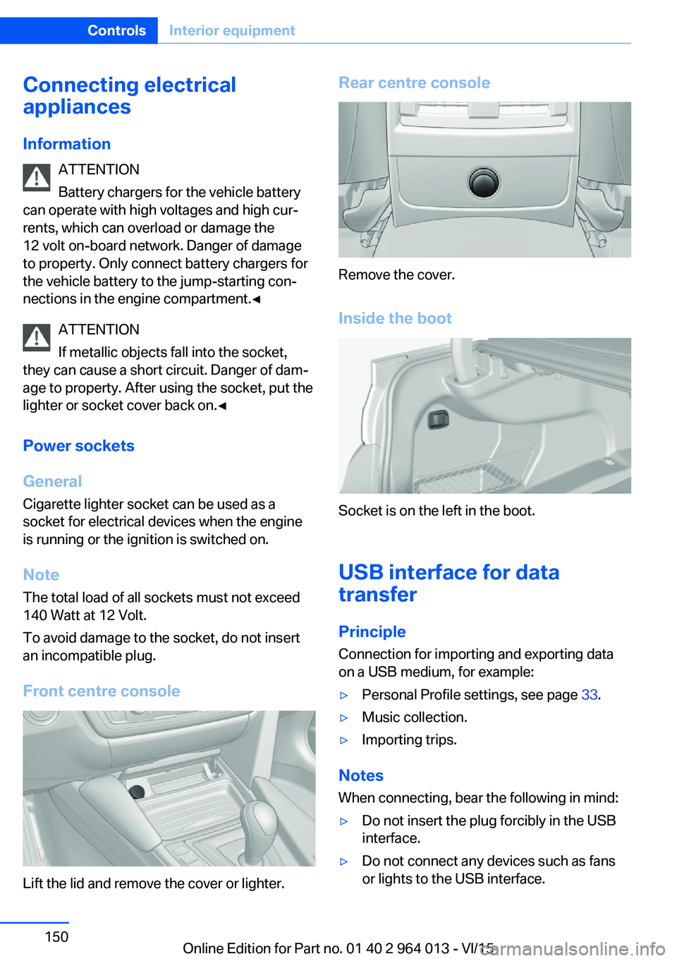
Front centre console
Lift the lid and remove the cover or lighter.
Rear centre console
Remove the cover.
Inside the boot
Socket is on the left in the boot.
USB interface for data
transfer
Principle Connection for importing and exporting data
on a USB medium, for example:
▷Personal Profile settings, see page 33.▷Music collection.▷Importing trips.
Notes
When connecting, bear the following in mind:
▷Do not insert the plug forcibly in the USB
interface.▷Do not connect any devices such as fans
or lights to the USB interface.Seite 150ControlsInterior equipment150
Online Edition for Part no. 01 40 2 964 013 - VI/15
Page 160 of 228

BMW M4 TechnologyVehicle equipment
This chapter describes all standard, national
and special equipment provided in the model
series. Equipment not available in the vehicle is
therefore also described, for example the se‐
lected special equipment or national version.
This also applies to safety-relevant functions
and systems. Comply with the relevant na‐
tional regulations when using the correspond‐
ing functions and systems.
High performance engine The high performance engine generates a
maximum power of 317 kW and a maximum
torque of 550 Nm from 3 litres of capacity.
With its spontaneous responsiveness, a very
broad usable engine speed range is produced.
The maximum engine speed is electronically regulated at 7,600 rpm. Due to the powerful
engine dynamics, the maximum engine speed
is limited when the vehicle is stationary.
Driving hot During the engine warm-up phase, the high
performance engine runs slightly more roughly
due to the emission control.
When the engine is cold, the exhaust has a
slightly metallic undertone, depending on the
system.
Other information for hot driving: engine speed
counter, see page 84, and engine oil tempera‐
ture, see page 84.
M compound brakes The high performance brake system has venti‐
lated compound brake discs.
Depending on design requirements, function
noises may occur when braking. However, thishas no effect on the performance, operational
safety and stability of the brakes.
Braking correctly
To keep the brake system in optimum condi‐
tion, it is desirable to load them at regular inter‐
vals depending on the nature of the vehicle.
M Carbon ceramic brakes
The high performance braking system has per‐
forated carbon ceramic brake disks and is de‐
signed for racetrack operation.
Depending on the material-specific properties, there can be increased functional noises when
braking, particularly when it is wet, shortly be‐
fore the vehicle comes to a stop. This has no
effect on performance, operational safety and
endurance of the brakes.
Due to the effect of wet and salt spray, for ex‐
ample, after using a car wash, condensation
overnight etc., the braking effect may corre‐
spond to a conventional braking system. This
can be detected as reduced braking effect and
compensated for by higher pedal pressure, as
needed.
Clean brake discs and brake calliper before
washing in an automatic car wash with a steam
sprayer or high pressure cleaner to avoid en‐
crustations and caking, for example, due to salt
crystals with a related stationary period. The cleaning effect of automatic car washes gener‐
ally not sufficient for this in the wheel area.
Also follow the information on this under vehi‐
cle washing, see page 208, and safe braking,
see page 163.Seite 160Driving hintsBMW M4 Technology160
Online Edition for Part no. 01 40 2 964 013 - VI/15
Page 161 of 228

Drivetrain
In this vehicle, particular attention is paid to the
direct connection from the engine to the drive‐
train. Due to the torsionally stiff design of the
drivetrain, as usual in a sports car, the trans‐
mission of the torque is can also be heard.
When there are load changes, it can therefore
cause clattering noises. They do not affect the
functioning or durability of the components.
Driving on a racing track
Requirements For driving on a racing track:▷Participation in a training course from
BMW Driving Experience.▷Check engine oil level and top up with en‐
gine oil as required.▷Have vehicle checked by a Service Partner
or a qualified specialist workshop.
Notes
Racing track operation causes increased wear. The vehicle is not designed for use in motor‐
sport competitions. This wear is not covered by the warranty.
The standard brake pads and the wear dis‐
plays are not designed for racing track opera‐
tion. Further information and advice are avail‐
able from a Service Partner or a qualified
specialist workshop.
Seite 161BMW M4 TechnologyDriving hints161
Online Edition for Part no. 01 40 2 964 013 - VI/15
Page 162 of 228

Driving precautionsVehicle equipmentThis chapter describes all standard, national
and special equipment provided in the model
series. Equipment not available in the vehicle is
therefore also described, for example the se‐
lected special equipment or national version.
This also applies to safety-relevant functions
and systems. Comply with the relevant na‐
tional regulations when using the correspond‐
ing functions and systems.
Running in General
Moving parts need a certain time to achieve
maximum operating efficiency as a unit.
The following information helps to achieve
maximum service life and efficiency of the ve‐
hicle.
Do not use Launch Control, see page 77, when
running in.
Engine, gearbox and differential
Up to 2000 km, 1200 miles Drive with alternating revolutions and speeds,
but do not exceed 5500 rpm and 170 km/h, ap‐ proximately 106 mph.
In principle, avoid full load or kick-down.
At 2000 km, 1200 miles
Have maintenance conduct a drive-in service.
From 2000 km, approximately
1200 miles to 5000 km, approximately
3100 miles
Revolutions and vehicle speed can gradually
be increased to a continuous speed of
220 km/h, approximately 137 mph.The maximum speed of 250 km/h, approxi‐
mately 155 mph is only to be used briefly, for
example when overtaking.
Tyres New tyres do not achieve their full road
grip immediately, for production reasons.
During the first 300 km, 200 miles, drive mod‐
erately.
Brake system
Brake pads and discs of the M compound
brakes only achieve a favourable wear and
contact pattern after approximately 500 km,
approximately 300 miles. Drive moderately
during this running-in period.
Brake discs and pads of the M carbon ceramic
brakes only achieve a favourable wear and
contact pattern after approx. 1000 km, approx.
600 miles. Drive moderately during this run‐
ning-in period.
Clutch
The clutch only begins to function optimally at
approximately 500 km, approximately
300 miles. Engage the clutch gently during this
running-in period.
After fitting new parts The same running-in procedures should be
observed if any of the components mentioned
above have to be renewed in the course of the
vehicle's operating life.Seite 162Driving hintsDriving precautions162
Online Edition for Part no. 01 40 2 964 013 - VI/15