2016 BMW M4 engine
[x] Cancel search: enginePage 191 of 228

MaintenanceVehicle equipment
This chapter describes all standard, national
and special equipment provided in the model
series. Equipment not available in the vehicle is
therefore also described, for example the se‐
lected special equipment or national version.
This also applies to safety-relevant functions
and systems. Comply with the relevant na‐
tional regulations when using the correspond‐
ing functions and systems.
BMW Maintenance System
The maintenance system points out the nec‐
essary maintenance measures and so sup‐
ports in maintaining the road and operational
safety of the vehicle.
Scopes and intervals may vary depending on
national version. Replacement work, spare
parts, operating materials and wear material
are calculated separately. Further information
is available from a Service Partner or a qualified
specialist workshop.
Condition Based Service,
CBS
Sensors and advanced algorithms monitor the
conditions in which your vehicle is used. Con‐
dition Based Service uses this information to
calculate the maintenance requirements.
The system thus enables adaptation of the
scope of maintenance to the individual usage
profile.
Detailed information on service requirements,
see page 87, can be displayed at the Control
Display.Service data in the remote control
Information on maintenance requirements is
continually saved in the remote control. The Service Partner or a qualified specialist work‐
shop can read out this data and suggest an op‐
timised maintenance scope for your vehicle.
This is why you should hand over the remote
control that was last used for driving to your
service advisor with the vehicle.
Periods out of use
Immobilisation periods with the vehicle battery
disconnected are not taken into account.
Updating the time-dependent maintenance
scope such as brake fluid and any engine oil
and microfilter or activated carbon filter can be
done by a Service Partner or a qualified spe‐
cialist workshop.
Service history Have maintenance and repair carried out by a
Service Partner or a qualified specialist work‐
shop.
The maintenance work carried out is entered in
the proof of maintenance and the vehicle data.
The entries are, just like a service booklet, evi‐
dence of regular maintenance.
If an entry is made in the electronic service his‐
tory of the vehicle, service-relevant data is not
only saved in the vehicle but also on the central
IT systems of BMW AG, Munich.
The data entered in the electronic service his‐
tory can also be viewed by the new vehicle
owner after a change of vehicle owner. In addi‐
tion, all Service Partners and other authorised
and qualified specialist workshops can view
the data entered in the electronic service his‐
tory.Seite 191MaintenanceMobility191
Online Edition for Part no. 01 40 2 964 013 - VI/15
Page 192 of 228

The vehicle owner can contact his/her Service
Partner or a qualified specialist workshop to
object to the entry in the electronic service his‐
tory, the associated data storage in the vehicle
and data transfer to the vehicle manufacturer,
in relation to his/her time as the vehicle owner.
In that case, no entry is made in the electronic
service history of the vehicle.
Maintenance entered is shown on the Control
Display, see page 88.
For Australia/New Zealand:
maintenance
No maintenance work other than normal main‐
tenance is required to keep the emission levels
of your vehicle within the design limits.
Socket for on-board
diagnosis, OBD
Note ATTENTION
Incorrect use of the on-board diagnosis
socket can result in malfunctions in the vehi‐
cle. Danger of damage to property. The on-
board diagnosis socket is only allowed to be
used by a Service Partner, a qualified specialist
workshop or other authorised persons.◀Position
The OBD socket for checking components de‐
finitive in terms of the composition of the ex‐
haust emissions is on the driver's side.
Emissions
▷The warning light flashes:
Engine malfunction that could
damage the catalytic converter.
Have the vehicle checked as soon
as possible.▷The warning light is illuminated:
Deterioration of exhaust emissions. Have
the vehicle checked as soon as possible.
Recycling
The manufacturer of your vehicle recommends
handing the vehicle in at a take-back point
nominated by the manufacturer at the end of
its life cycle. The regulations concerning the
returning of end-of-life vehicles may vary from
country to country. Further information is avail‐
able from a Service Partner or a qualified spe‐
cialist workshop.
Seite 192MobilityMaintenance192
Online Edition for Part no. 01 40 2 964 013 - VI/15
Page 200 of 228

Recharging the battery
General Ensure the battery is sufficiently charged to
guarantee the entire lifetime of the battery.
In the following cases, charging the battery is
necessary:▷When making frequent short trips.▷When leaving for periods of longer than
one month.
Notes
ATTENTION
Unsuitable external chargers can dam‐
age the vehicle. Danger of damage to property.
Use chargers that have been categorised as
suitable for the respective vehicle type by the
vehicle manufacturer. Observe the maximum
charge voltage.◀
Maximum charge voltage: 14.4 Volt. ATTENTION
Battery chargers for the vehicle battery
can operate with high voltages and high cur‐
rents, which can overload or damage the
12 volt on-board network. Danger of damage
to property. Only connect battery chargers for
the vehicle battery to the jump-starting con‐
nections in the engine compartment.◀
Jump-starting connections
Recharge the battery only with the engine
stopped, via the jump-starting connections,
see page 204, in the engine compartment.
Charger
Chargers developed especially for the vehicle
and attuned to the on-board network can be
obtained from Service Partner or a qualified
specialist workshop.
Power failure
Following a temporary electrical power outage,
some equipment will have to be reinitialised or
individual settings will need to be updated, for
example:▷Seat and mirror memory: re-save positions.▷Time: update.▷Date: update.▷Glass Roof and sun blind: initialise system,
see page 47.
Disposing of the old battery
Dispose of old batteries at a Service
Partner or a qualified specialist work‐
shop or hand them into an authorised
collecting point.
Fuses
Notes WARNING
Incorrect or repaired fuses can overload
electrical cables and components. Fire risk. Do
not repair blown fuses or renew them by fuses
with a different colour or amp rating.◀
Plastic tweezers and details of the fuse assign‐
ment can be found with the fuses in the boot.
Seite 200MobilityReplacing parts200
Online Edition for Part no. 01 40 2 964 013 - VI/15
Page 201 of 228

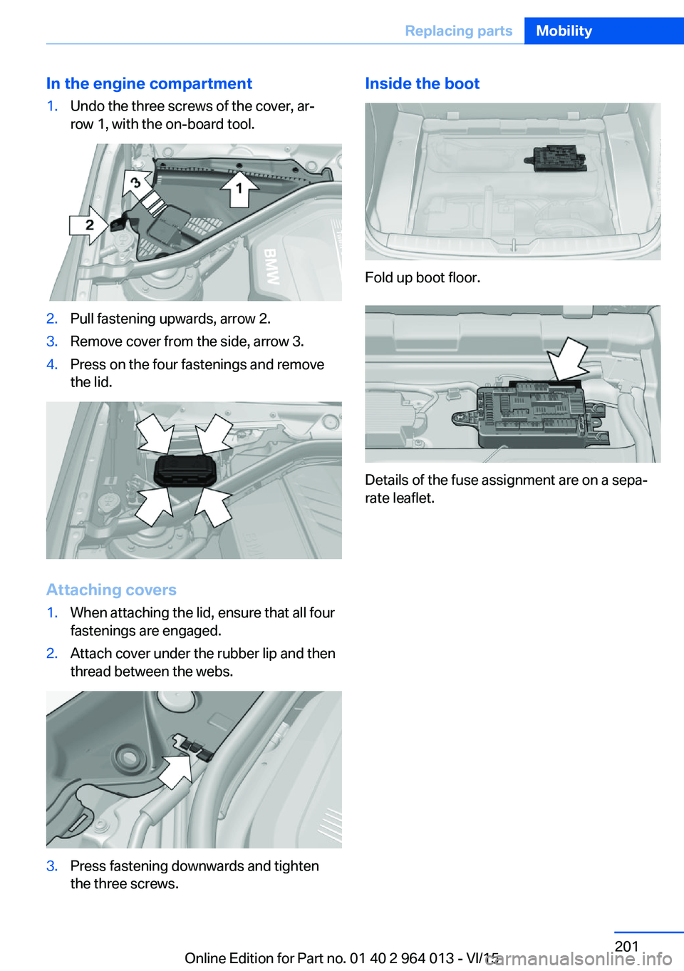
In the engine compartment1.Undo the three screws of the cover, ar‐
row 1, with the on-board tool.2.Pull fastening upwards, arrow 2.3.Remove cover from the side, arrow 3.4.Press on the four fastenings and remove
the lid.
Attaching covers
1.When attaching the lid, ensure that all four
fastenings are engaged.2.Attach cover under the rubber lip and then
thread between the webs.3.Press fastening downwards and tighten
the three screws.Inside the boot
Fold up boot floor.
Details of the fuse assignment are on a sepa‐
rate leaflet.
Seite 201Replacing partsMobility201
Online Edition for Part no. 01 40 2 964 013 - VI/15
Page 203 of 228

required. For example, the current position
of the vehicle, if this can be determined. If
questions posed by the emergency call
centre remain unanswered, rescue meas‐
ures are automatically initiated.▷If the LED is flashing green but the emer‐
gency call centre can no longer be heard
over the loudspeaker, you may still be able
to be heard by the emergency call centre.
Automatically activating emergency
calls
In certain circumstances, an emergency call
may be placed automatically immediately after
a serious accident. An automatic emergency
call is not influenced by pressing the SOS but‐
ton.
Warning triangle
The warning triangle is located inside the boot
lid.
To remove, release the mounts.
First-aid kit
Note The longevity of some items is limited.
Check the use-by dates of the contents regu‐
larly and replace any items that have expired in
good time.
Storage
The first-aid kit is located on the right in a stor‐
age compartment in the boot.
Starting assistance General
If the vehicle battery is discharged, the engine
can be started using two jump leads from an‐
other vehicle's battery. Use only jump leads
with fully insulated terminal clamps.
Information DANGER
Touching live components can result in
an electric shock. Danger of injury or life. Do
not touch any components that could be live.◀
Do not deviate from the procedure described
below, otherwise personal injury could result or
both vehicles could be damaged.
Preparations ATTENTION
Contact between the bodies of the two
vehicles can result in a short circuit during
starting assistance. Danger of damage to prop‐
erty. Make sure there is no contact between
the bodies.◀
1.Check whether the battery in the other ve‐
hicle shows 12 volts. Specifications are on
the battery.2.Switch off the engine of the donor vehicle.Seite 203Help in the event of a breakdownMobility203
Online Edition for Part no. 01 40 2 964 013 - VI/15
Page 204 of 228

3.Switch off any electrical systems in both
vehicles.
Jump-starting connections
WARNING
Connecting the jump leads in the wrong
sequence can cause sparks. Danger of injury.
Comply with the correct sequence when con‐
necting up.◀
The jump-starting connection in the engine
compartment serves as the positive battery
terminal.
Open the cover of the starting assistance con‐
nection.
The battery negative terminal is the body earth
or a special nut.
Connecting the cables
1.Open the cover of the BMW starting assis‐
tance connection.2.Connect a terminal clamp on the positive/+
jump lead to the positive terminal of the
battery or the corresponding jump-starting
connection on the donor vehicle.3.Connect the other terminal clamp to the
battery's positive terminal or to the corre‐
sponding jump-starting connection on the
vehicle to be started.4.Connect a terminal clamp on the negative/–
jump lead to the negative terminal of the
battery or the corresponding engine or
body earth connection on the donor vehi‐
cle.5.Connect the second terminal clamp to the
negative terminal of the battery or to a
ground/earth connection on the corre‐
sponding engine or body of the vehicle to
be started.
Starting the engine
Do not use the spray products sold as starting
aids.
1.Start the engine of the donor vehicle and
allow it to run for a few minutes at a slightly
increased idle speed.2.Start the engine of the vehicle to be started
as normal.
If an initial attempt to start the engine fails,
wait several minutes until the flat battery
has been recharged to a slightly greater
degree.3.Allow both engines to run for a few mi‐
nutes.4.Disconnect the jump leads in the opposite
order from that in which they were origi‐
nally attached.
Check the battery if necessary and have it re‐
charged.
Tow-starting and towing Information WARNING
Due to system limitations, there may be
malfunctions of individual functions when tow-
starting/towing with activated Intelligent Safety
Seite 204MobilityHelp in the event of a breakdown204
Online Edition for Part no. 01 40 2 964 013 - VI/15
Page 205 of 228

Systems, for example approach control warn‐
ing with light braking function. Danger of acci‐
dents. Switch off all Intelligent Safety Systems
before tow-starting/towing.◀
Manual gearboxGearshift lever in idle position.
Being towed Observe the following information:▷Make sure that the ignition is switched on,
otherwise low-beam headlights, rear lights,
turn indicators and wipers would not be
available.▷Do not tow the vehicle with the rear axle
raised, otherwise the steering can turn.▷When the engine is not running, there is no
power assistance and the brake servo is
out of action. The steering and brakes will
require extra effort to operate.▷Greater steering wheel movements are
necessary.▷The towing vehicle must not be lighter
than the towed vehicle, otherwise it may be
unable to keep the towed vehicle reliably
under control.▷Do not exceed a towing speed of on
50 km/h, 30 mph.▷Do not exceed a towing distance of 50 km,
30 miles.Towing truck
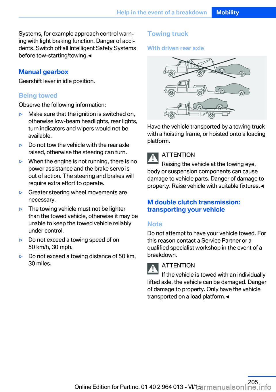
With driven rear axle
Have the vehicle transported by a towing truck
with a hoisting frame, or hoisted onto a loading
platform.
ATTENTION
Raising the vehicle at the towing eye,
body or suspension components can cause
damage to vehicle parts. Danger of damage to
property. Raise vehicle with suitable fixtures.◀
M double clutch transmission:
transporting your vehicle
Note
Do not attempt to have your vehicle towed. For
this reason contact a Service Partner or a
qualified specialist workshop in the event of a
breakdown.
ATTENTION
If the vehicle is towed with an individually
lifted axle, the vehicle can be damaged. Danger
of damage to property. Only have the vehicle
transported on a load platform.◀
Seite 205Help in the event of a breakdownMobility205
Online Edition for Part no. 01 40 2 964 013 - VI/15
Page 207 of 228

NotesATTENTION
If the towing eye is not used as intended,
the vehicle or towing eye is damaged. Danger
of damage to property. Observe the notes on
using the towing eye.◀
Using the towing eye:▷Use only the towing eye supplied with the
vehicle, and make sure that it is screwed in
fully and is tight.▷Only use the towing eye for towing on nor‐
mal roads (in other words not off-road).▷Use the towing eye screwed into the
socket at the front of the vehicle for ma‐
noeuvring only.▷Avoid lateral loads on the towing eye, for
example do not raise the vehicle at the
towing eye.
Thread for towing eye
Press the marking on the front cover to press it
out.
Use the screwdriver from the on-board toolkit
to press out the rear cover at the opening.
Tow-starting
M double clutch transmission Do not attempt to tow-start or push-start the
vehicle.
Due to the M double clutch transmission it is
not possible to start the engine by towing.
Have the cause of the starting difficulties recti‐
fied.
Manual gearbox If possible, do not tow-start the vehicle but
start the engine using starting assistance, see
page 203. Only tow-start when the engine is
cold if your vehicle has a catalytic converter.1.Switching on hazard warning lights, please
observe country-specific regulations.2.Ignition, see page 65, on.3.Insert 3rd gear.4.Tow-start with the clutch depressed and
release the clutch slowly. Depress the
clutch again immediately after the engine
starts.5.Stop in a suitable location, remove the tow
bar or towing rope and switch off the haz‐
ard warning lights.6.Have the vehicle checked.Seite 207Help in the event of a breakdownMobility207
Online Edition for Part no. 01 40 2 964 013 - VI/15