2016 BMW M4 engine
[x] Cancel search: enginePage 91 of 228
Calling up information on the
information display
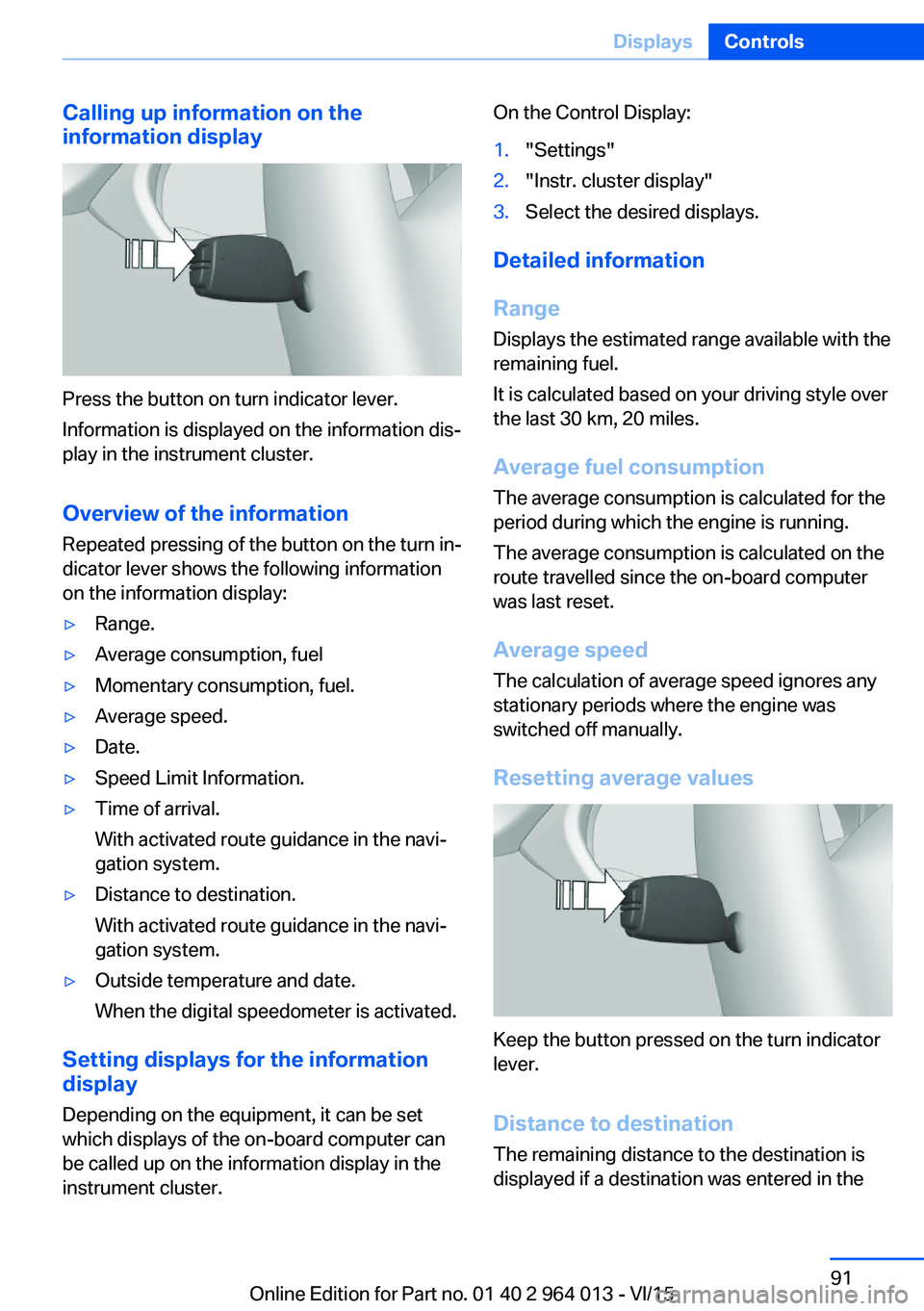
Press the button on turn indicator lever.
Information is displayed on the information dis‐
play in the instrument cluster.
Overview of the information
Repeated pressing of the button on the turn in‐
dicator lever shows the following information
on the information display:
▷Range.▷Average consumption, fuel▷Momentary consumption, fuel.▷Average speed.▷Date.▷Speed Limit Information.▷Time of arrival.
With activated route guidance in the navi‐
gation system.▷Distance to destination.
With activated route guidance in the navi‐
gation system.▷Outside temperature and date.
When the digital speedometer is activated.
Setting displays for the information
display
Depending on the equipment, it can be set
which displays of the on-board computer can
be called up on the information display in the
instrument cluster.
On the Control Display:1."Settings"2."Instr. cluster display"3.Select the desired displays.
Detailed information
Range
Displays the estimated range available with the
remaining fuel.
It is calculated based on your driving style over
the last 30 km, 20 miles.
Average fuel consumption
The average consumption is calculated for the
period during which the engine is running.
The average consumption is calculated on the
route travelled since the on-board computer
was last reset.
Average speed
The calculation of average speed ignores any
stationary periods where the engine was
switched off manually.
Resetting average values
Keep the button pressed on the turn indicator
lever.
Distance to destination
The remaining distance to the destination is
displayed if a destination was entered in the
Seite 91DisplaysControls91
Online Edition for Part no. 01 40 2 964 013 - VI/15
Page 95 of 228

Switching on/off1."Settings"2."Head-up display"3."Head-up display"
Display
Standard view The following information is displayed in the
Head-Up Display:
▷Speed.▷Navigation system.▷Check Control messages.▷Selection list from the instrument cluster.▷Driver Assistance Systems.
Some of this information is only shown briefly
when needed.
M View
1Current engine speed, highlighted2Shift Lights3Forewarning field, engine speed display4Red warning field, engine speed display5Speed6Gear display/warning messages7Speed Limit Information with No Passing
Information
Activate M View:
Select displays in the head-up display.
Selecting displays on the Head-Up
Display
On the Control Display:1."Settings"2."Head-up display"3."Information displayed"4.Select desired display on Head-Up Dis‐
play.
Adjusting brightness
The brightness is automatically adapted to the
ambient light.
The base setting can be adjusted manually.
On the Control Display:
1."Settings"2."Head-up display"3."Brightness"4.Turn the Controller until the desired bright‐
ness is obtained.5.Press the Controller.
The brightness of the Head-Up Display can
also be influenced using the instrument light‐
ing if the low-beam headlights are switched on.
The setting is saved for the currently used pro‐
file.
Adjusting height
On the Control Display:
1."Settings"2."Head-up display"3."Height"4.Turn the Controller until the desired height
is obtained.5.Press the Controller.
The setting is saved for the currently used pro‐
file.
Seite 95DisplaysControls95
Online Edition for Part no. 01 40 2 964 013 - VI/15
Page 96 of 228
Adjusting rotation
The image of the Head-Up Display can be ro‐
tated around its axis.
On the Control Display:1."Settings"2."Head-up display"3."Rotation"4.Turn the Controller until the desired set‐
ting is reached.5.Press the Controller.
The setting is saved for the currently used pro‐
file.
Special windscreen
The windscreen constitutes part of the sys‐
tem.
The shape of the windscreen enables a precise
projection.
A film in the windscreen prevents double im‐
ages occurring.
For this reason, have the special windscreen
replaced by a Service Partner or a qualified
specialist workshop.
Shift Lights General
The display is on the Head-Up Display and in
the instrument cluster.
Shift Lights in the instrument cluster
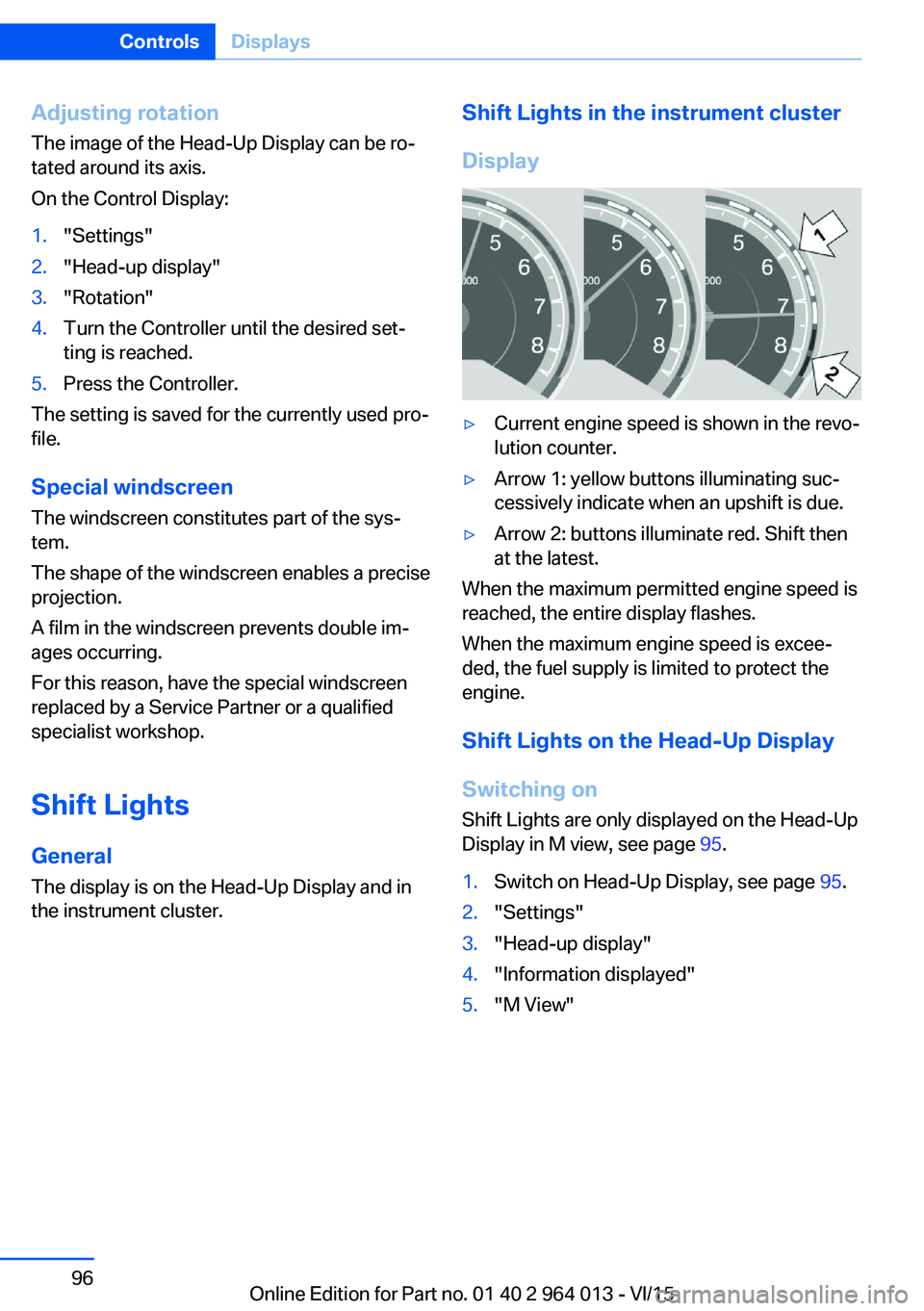
Display▷Current engine speed is shown in the revo‐
lution counter.▷Arrow 1: yellow buttons illuminating suc‐
cessively indicate when an upshift is due.▷Arrow 2: buttons illuminate red. Shift then
at the latest.
When the maximum permitted engine speed is
reached, the entire display flashes.
When the maximum engine speed is excee‐
ded, the fuel supply is limited to protect the
engine.
Shift Lights on the Head-Up DisplaySwitching on Shift Lights are only displayed on the Head-Up
Display in M view, see page 95.
1.Switch on Head-Up Display, see page 95.2."Settings"3."Head-up display"4."Information displayed"5."M View"Seite 96ControlsDisplays96
Online Edition for Part no. 01 40 2 964 013 - VI/15
Page 97 of 228
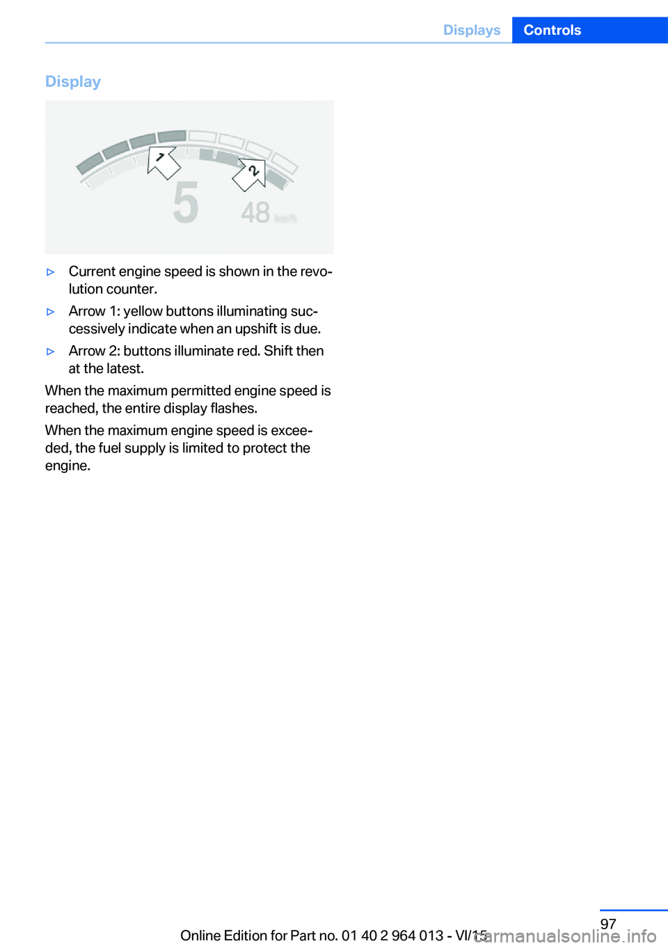
Display▷Current engine speed is shown in the revo‐
lution counter.▷Arrow 1: yellow buttons illuminating suc‐
cessively indicate when an upshift is due.▷Arrow 2: buttons illuminate red. Shift then
at the latest.
When the maximum permitted engine speed is
reached, the entire display flashes.
When the maximum engine speed is excee‐
ded, the fuel supply is limited to protect the
engine.
Seite 97DisplaysControls97
Online Edition for Part no. 01 40 2 964 013 - VI/15
Page 98 of 228
LightsVehicle equipmentThis chapter describes all standard, national
and special equipment provided in the model
series. Equipment not available in the vehicle is
therefore also described, for example the se‐
lected special equipment or national version.
This also applies to safety-relevant functions
and systems. Comply with the relevant na‐
tional regulations when using the correspond‐
ing functions and systems.
Overview Switch in the vehicle
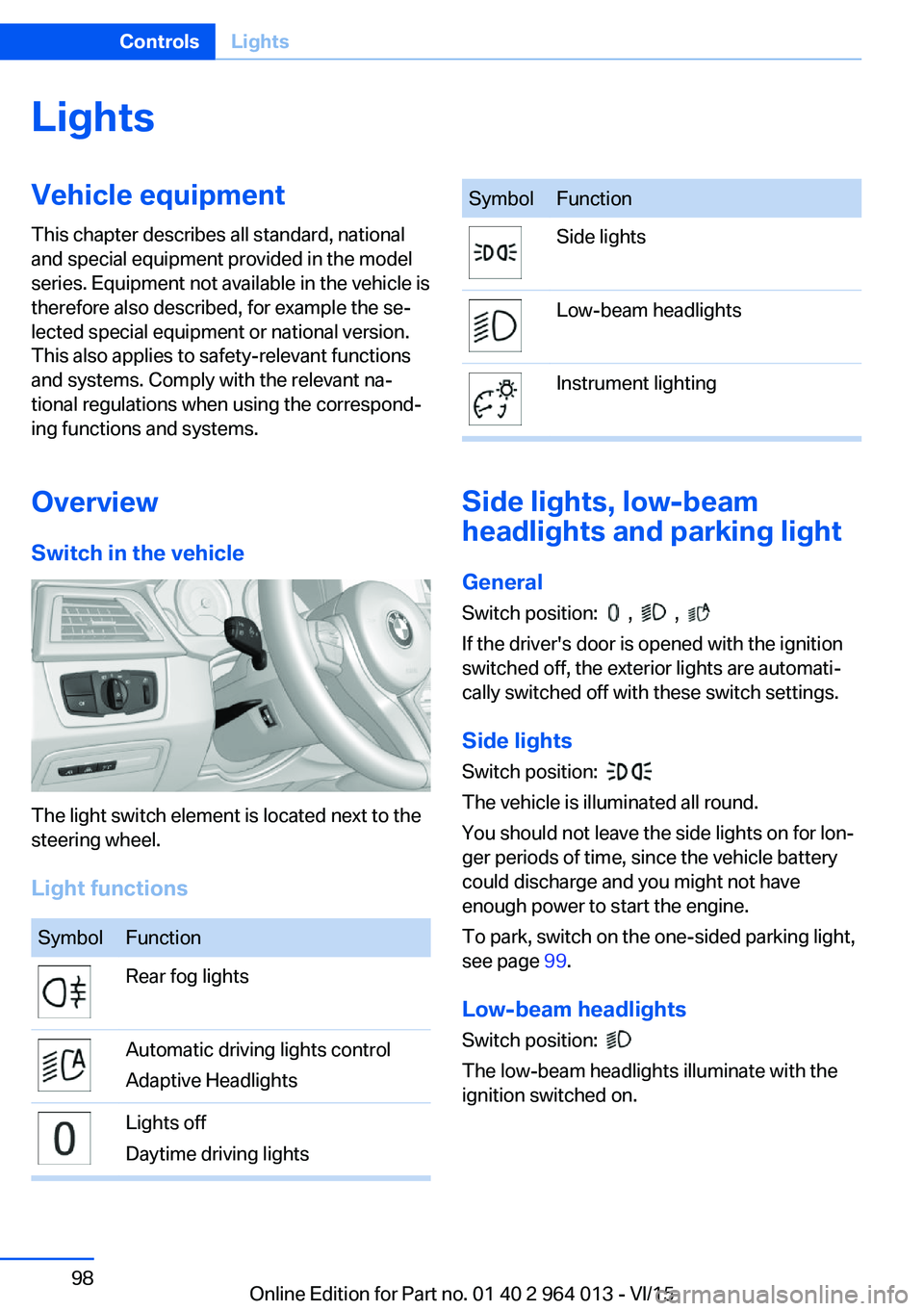
The light switch element is located next to the
steering wheel.
Light functions
SymbolFunctionRear fog lightsAutomatic driving lights control
Adaptive HeadlightsLights off
Daytime driving lightsSymbolFunctionSide lightsLow-beam headlightsInstrument lighting
Side lights, low-beam
headlights and parking light
General
Switch position:
, ,
If the driver's door is opened with the ignition
switched off, the exterior lights are automati‐
cally switched off with these switch settings.
Side lights
Switch position:
The vehicle is illuminated all round.
You should not leave the side lights on for lon‐
ger periods of time, since the vehicle battery
could discharge and you might not have
enough power to start the engine.
To park, switch on the one-sided parking light,
see page 99.
Low-beam headlights Switch position:
The low-beam headlights illuminate with the
ignition switched on.
Seite 98ControlsLights98
Online Edition for Part no. 01 40 2 964 013 - VI/15
Page 107 of 228
Tyre Pressure Monitor TPM
Principle The system monitors the tyre pressure in the
four fitted tyres. The system warns if the infla‐
tion pressure in one or more tyres has fallen
considerably. To do this, the sensors in the
tyre valves measure the tyre pressure and tyre
temperatures.
Note
To operate the system, also follow the other
information and notes under tyre inflation pres‐
sure, see page 175.
Operating requirements For the system, a reset must have been made
with the correct tyre inflation pressure, other‐
wise reliable signalling of a flat tyre cannot be assured.
Reset the system after adjusting the tyre pres‐
sure to a new value and after a tyre or wheel
change.
Always use wheels with TPM electronics to
guarantee the system functions without errors.
Status display
The current status of the Tyre Pressure Moni‐
tor TPM can be shown on the Control Display,
for example whether the TPM is active.
On the Control Display:1."Vehicle information"2."Vehicle status"3. "Tyre Pressure Monitor (RDC)"
The status is displayed.
Status control display The tyre and system status is denoted by the
wheel colour and some text on the Control Dis‐
play.
All wheels green
System is active and is warning about the tyre
inflation pressures stored during the last reset.
One wheel yellow
A flat tyre or major loss of tyre inflation pres‐
sure in the tyre shown.
All wheels yellow
A flat tyre or major loss of tyre inflation pres‐
sure in several tyres.
Wheels grey
The system cannot detect a flat tyre. The rea‐
sons for this are:▷System reset is performed.▷Malfunction.
Additional information
The current tyre inflation pressures and, de‐
pending on the model, tyre temperatures are
also displayed in the status control display.
The values shown are current values and may
change due to the effect of driving mode or
weather conditions.
Running reset Reset the system after adjusting the tyre pres‐
sure to a new value and after a tyre or wheel
change.
On the Control Display and on the vehicle:
1."Vehicle information"2."Vehicle status"3. "Perform reset"4.Start the engine – do not drive off.5.Resetting tyre pressure: "Perform reset".6.Drive off.
The wheels are shown grey and the status ap‐
pears on the display.
After driving for a short time over 30 km/h,
19 mph the set tyre inflation pressures are ac‐
Seite 107SecurityControls107
Online Edition for Part no. 01 40 2 964 013 - VI/15
Page 109 of 228

Runflat indicator RPA
Principle The system identifies a loss of tyre pressure
by comparing the speeds of rotation of the in‐
dividual wheels while the vehicle is in motion.
If a tyre loses pressure, its diameter changes.
This in turn alters the rotational speed of the
corresponding wheel. This is detected and re‐
ported as a flat tyre.
The system does not measure the tyre pres‐
sures as such.
Operating requirements
The system must have been initialised with
correct tyre inflation pressure, otherwise relia‐
ble signalling of a flat tyre cannot be assured.
Each time the tyre pressure is adjusted or a
tyre or wheel is changed, initialise the system
again.
Status display The current status of the runflat indicator can
be shown on the Control Display, for example
whether the runflat indicator is active.
On the Control Display:1."Vehicle information"2."Vehicle status"3. "Flat Tyre Monitor (RPA)"
The status is displayed.
Initialising
On initialisation, the current tyre pressures are
stored as a reference for detection of a flat tyre. The initialisation is started by confirming
the correct tyre inflation pressures.
When driving with snow chains fitted, do not
initialise the system.
On the Control Display:
1."Vehicle information"2."Vehicle status"3. "Perform reset"4.Start the engine – do not drive off.5.Start the initialisation with "Perform reset".6.Drive off.
Initialising is completed while the vehicle is in
motion; this process can be interrupted at any
time.
Initialising resumes automatically when you
continue your journey.
Message of a flat tyre The yellow warning lamp is illuminated.
A Check Control message is shown.
There is a flat tyre or substantial loss of
tyre pressure.
1.Reduce your speed and carefully stop the
vehicle. Avoid violent or sudden braking
and steering manoeuvres.2.Determine which wheel is damaged. Do
this by checking the tyre inflation pres‐
sures with the aid of the Mobility System. If
all tyres are inflated to the correct pres‐
sures, the runflat indicator might not have
been initialised. In this case initialise the
system.3.Remedy the flat tyre with the Mobility Sys‐
tem or replace the damaged wheel.
System limits
A natural, even loss of tyre pressurein all four
tyres that occurs over time is not detected.
Consequently, check the tyre inflation pres‐
sure at regular intervals.
No warning can be given in the event of sud‐
den tyre failure caused by external factors.
In the following situations, the system could be
slow to respond or operate incorrectly:
▷If the system has not been initialised.▷Journey on snow-covered or slippery sur‐
faces.Seite 109SecurityControls109
Online Edition for Part no. 01 40 2 964 013 - VI/15
Page 110 of 228

▷Dynamic driving style, causing the drive
gears to spin, high lateral acceleration.▷Driving with snow chains.
Intelligent Safety
Principle
Intelligent Safety permits central operation of
driver assistance systems.
Depending on equipment, Intelligent Safety
consists of one or more systems which can
help to avoid the risk of a collision. These sys‐
tems are automatically active each time you
start the engine with the start/stop button:
▷Front-end collision warning with city brak‐
ing function, see page 111.▷Person warning, see page 113.
Notes
WARNING
Displays and warnings do not take your
personal responsibility from you. System limi‐
tations can mean that warnings or system re‐
sponses are not issued, are issued too late, or are issued incorrectly. Danger of accidents.
Adapt driving style to the driving conditions.
Observe the traffic situation and intervene ac‐
tively if the situation warrants it.◀
WARNING
Due to system limitations, there may be
malfunctions of individual functions when tow-
starting/towing with activated Intelligent Safety Systems, for example approach control warn‐
ing with light braking function. Danger of acci‐
dents. Switch off all Intelligent Safety Systems
before tow-starting/towing.◀
Overview
Button in the vehicle
Intelligent Safety button
Camera
The camera is in the area of the base of the
rear-view mirror.
Keep the windscreen clean and clear in the
area in front of the rear view mirror.
Switching on/offThe Intelligent Safety Systems are active auto‐
matically at the start of each journey.
Press button: the systems are
switched off again. LED turns off.
Press button again: the systems are switched
on. LED is illuminated.
Settings can be adjusted on the Control Dis‐
play.
Seite 110ControlsSecurity110
Online Edition for Part no. 01 40 2 964 013 - VI/15