2016 BMW M4 turn signal
[x] Cancel search: turn signalPage 37 of 228

In some equipment versions, doors are also
unlocked if appropriate
To prevent the remote control from being
locked in, do not place the remote control in
the boot.
If the doors were not unlocked, the boot lid is
locked again as soon as it is closed.
Malfunction
Detection of the remote control by the vehicle
may be disrupted by the following circumstan‐
ces, amongst others:▷The battery of the remote control is dis‐
charged. Replacing the battery, see
page 33.▷Disruption of the radio link by transmission
masts or other equipment transmitting
powerful signals.▷Shielding of the remote control by metallic
objects.▷Disruption of the radio link by mobile tele‐
phones or other electronic devices in the
immediate vicinity.
Do not transport the remote control together
with metallic objects or electronic devices.
If there is a malfunction, the vehicle can also be
unlocked and locked from the outside without
remote control, see page 37.
Without remote control
From outside WARNING
If the vehicle is locked from the outside, it
cannot be unlocked from the inside in some
country versions.
If persons must remain in the vehicle for an ex‐ tended period of time and are exposed to ex‐
treme heat or cold, there is a risk of injury or
life. Do not lock the vehicle from the outside
when there is someone inside it.◀
ATTENTION
The door lock is firmly connected to the
door. The door handle can be moved. Pulling
the door handle when the integrated key is in‐
serted can damage the paint or the key. Dan‐
ger of damage to property. Pull out the
integrated key before pulling on the outer door
handle.◀
Unlock or lock the driver's door using the
integrated key, see page 32, in the door lock.
The other doors must be unlocked or locked
from the inside.
Alarm system
The alarm system is not armed if the vehicle is
locked with the integrated key.
Alarm system is triggered if the vehicle has
been unlocked using the door lock.
To end this alarm, unlock the vehicle with the
remote control or turn on the ignition, with
special ID of the remote control, see page 33,
as necessary.
Seite 37Opening and closingControls37
Online Edition for Part no. 01 40 2 964 013 - VI/15
Page 42 of 228

Boot lid is opened and doors are un‐
locked.
Acknowledgement signal of the
vehicle
Settings are saved in active profile, see
page 33.
1."Settings"2."Doors/key"3."Turn signals for lock/unl."
Automatic locking
Settings are saved in active profile, seepage 33.
1."Settings"2."Doors/key"3.Select the desired function:▷"Automatic relock"
The vehicle is locked automatically af‐
ter a short while if no door is opened.▷"Lock after driving away"
On driving off, the vehicle is locked au‐
tomatically.
Calling up seat, mirror setting
The last adjusted driver's seat and exterior mir‐
ror position is saved for the currently used re‐
mote control.
When the vehicle is unlocked, this position is
called up automatically if the function has been
enabled.
WARNING
Danger of trapping when moving the
seats. Danger of injury or damage to property.
Before making the setting, make sure that the
movement area of the seat is clear.◀
Adjustment procedure is interrupted:
▷By operating the switch or the seat adjust‐
ment.▷By touching a button of the seat and mirror
memory.
Enabling setting
1."Settings"2."Doors/key"3."Last seat position autom."
Alarm system
PrincipleThe alarm system is triggered when the vehi‐cle is locked if:
▷A door, the bonnet or the the boot lid is
opened.▷Movements in the interior.▷The vehicle's incline changes, for instance
if an attempt is made to jack it up and steal
the wheels or to raise it prior to towing
away.▷There is an interruption in the power sup‐
ply from the battery.
The alarm system will respond briefly to unau‐
thorised attempts to access the vehicle as fol‐
lows:
▷Acoustic alarm.▷Switching on the hazard warning lights.
Arming and disarming
At the same time as unlocking and locking the
vehicle by remote control or Comfort Access
the alarm system is also disarmed or armed.
Door lock with alarm system armed Alarm system is deactivated if the vehicle is
unlocked using the door lock.
Boot lid with alarm system armed The boot lid can be opened even with the
alarm system armed.
Seite 42ControlsOpening and closing42
Online Edition for Part no. 01 40 2 964 013 - VI/15
Page 70 of 228

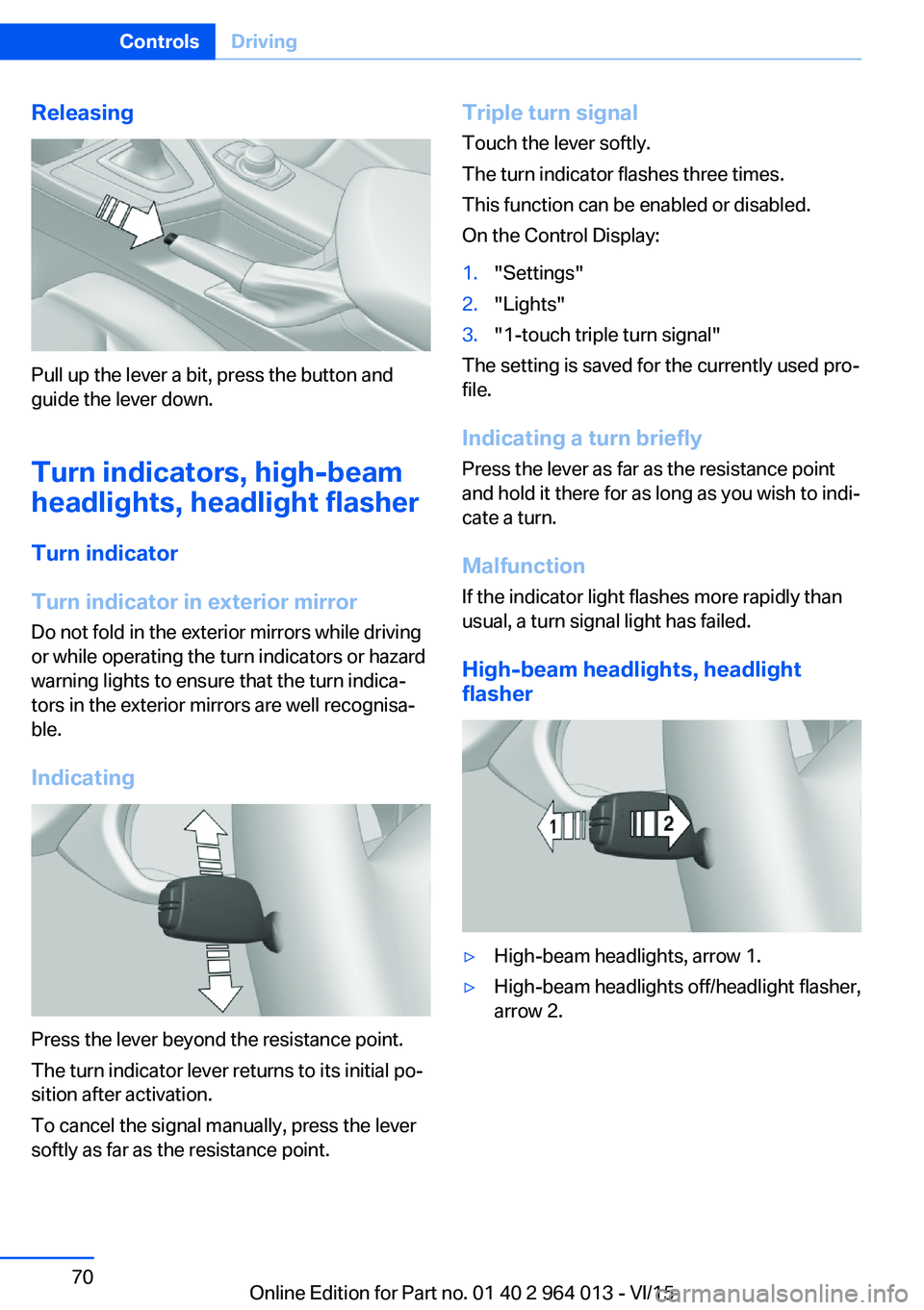
Releasing
Pull up the lever a bit, press the button and
guide the lever down.
Turn indicators, high-beam
headlights, headlight flasher
Turn indicator
Turn indicator in exterior mirror
Do not fold in the exterior mirrors while driving
or while operating the turn indicators or hazard
warning lights to ensure that the turn indica‐
tors in the exterior mirrors are well recognisa‐
ble.
Indicating
Press the lever beyond the resistance point.
The turn indicator lever returns to its initial po‐
sition after activation.
To cancel the signal manually, press the lever
softly as far as the resistance point.
Triple turn signal
Touch the lever softly.
The turn indicator flashes three times.
This function can be enabled or disabled.
On the Control Display:1."Settings"2."Lights"3."1-touch triple turn signal"
The setting is saved for the currently used pro‐
file.
Indicating a turn briefly
Press the lever as far as the resistance point
and hold it there for as long as you wish to indi‐
cate a turn.
Malfunction
If the indicator light flashes more rapidly than
usual, a turn signal light has failed.
High-beam headlights, headlight
flasher
▷High-beam headlights, arrow 1.▷High-beam headlights off/headlight flasher,
arrow 2.Seite 70ControlsDriving70
Online Edition for Part no. 01 40 2 964 013 - VI/15
Page 82 of 228

▷Wheel without TPM electronics is fitted:
have the vehicle checked by a Service
Partner or a qualified specialist workshop if
necessary.▷Malfunction: have the system checked by a
Service Partner or a qualified specialist
workshop.
For more information, see Tyre Pressure Moni‐
tor, see page 107.
Steering system Steering system faulty.
Have steering system checked by a
Service Centre or a qualified specialist
workshop.
Engine functions Have vehicle checked by a Service
Centre or a qualified specialist work‐
shop.
For further information see socket for on-
board diagnosis, see page 192.
Lane departure warning System is switched on and warns you
under certain conditions if you leave a
detected lane without indicating first.
For further information see Lane Departure
Warning, see page 115.
Manual speed limiter Illuminating: the system is switched on.
Flashing: set speed limit exceeded. An
acoustic signal may sound.
Reduce speed or deactivate system.
Rear fog lights Rear fog lights are switched on.
For further information see rear fog lights, see
page 102.
Green lights Turn indicator Turn signal is switched on.If the indicator light flashes more rap‐
idly than usual, a turn signal light has
failed.
For further information see turn indicator, see
page 70.
Side lights, driving lights Side lights or driving lights are
switched on.
For further information see side lights/
low-beam headlights, low-beam headlight
control, see page 98.
High-beam assistance High-beam assistance is switched on.
High-beam headlights are switched on
and off automatically depending on the
traffic situation.
For further information see high beam assis‐
tance, see page 100.
Cruise Control The system is switched on. The speed
set using the control functions on the
steering wheel is maintained.
Blue lights
High-beam headlights High-beam headlights are switched on.
For further information see high-beam
headlights, see page 70.Seite 82ControlsDisplays82
Online Edition for Part no. 01 40 2 964 013 - VI/15
Page 109 of 228

Runflat indicator RPA
Principle The system identifies a loss of tyre pressure
by comparing the speeds of rotation of the in‐
dividual wheels while the vehicle is in motion.
If a tyre loses pressure, its diameter changes.
This in turn alters the rotational speed of the
corresponding wheel. This is detected and re‐
ported as a flat tyre.
The system does not measure the tyre pres‐
sures as such.
Operating requirements
The system must have been initialised with
correct tyre inflation pressure, otherwise relia‐
ble signalling of a flat tyre cannot be assured.
Each time the tyre pressure is adjusted or a
tyre or wheel is changed, initialise the system
again.
Status display The current status of the runflat indicator can
be shown on the Control Display, for example
whether the runflat indicator is active.
On the Control Display:1."Vehicle information"2."Vehicle status"3. "Flat Tyre Monitor (RPA)"
The status is displayed.
Initialising
On initialisation, the current tyre pressures are
stored as a reference for detection of a flat tyre. The initialisation is started by confirming
the correct tyre inflation pressures.
When driving with snow chains fitted, do not
initialise the system.
On the Control Display:
1."Vehicle information"2."Vehicle status"3. "Perform reset"4.Start the engine – do not drive off.5.Start the initialisation with "Perform reset".6.Drive off.
Initialising is completed while the vehicle is in
motion; this process can be interrupted at any
time.
Initialising resumes automatically when you
continue your journey.
Message of a flat tyre The yellow warning lamp is illuminated.
A Check Control message is shown.
There is a flat tyre or substantial loss of
tyre pressure.
1.Reduce your speed and carefully stop the
vehicle. Avoid violent or sudden braking
and steering manoeuvres.2.Determine which wheel is damaged. Do
this by checking the tyre inflation pres‐
sures with the aid of the Mobility System. If
all tyres are inflated to the correct pres‐
sures, the runflat indicator might not have
been initialised. In this case initialise the
system.3.Remedy the flat tyre with the Mobility Sys‐
tem or replace the damaged wheel.
System limits
A natural, even loss of tyre pressurein all four
tyres that occurs over time is not detected.
Consequently, check the tyre inflation pres‐
sure at regular intervals.
No warning can be given in the event of sud‐
den tyre failure caused by external factors.
In the following situations, the system could be
slow to respond or operate incorrectly:
▷If the system has not been initialised.▷Journey on snow-covered or slippery sur‐
faces.Seite 109SecurityControls109
Online Edition for Part no. 01 40 2 964 013 - VI/15
Page 112 of 228

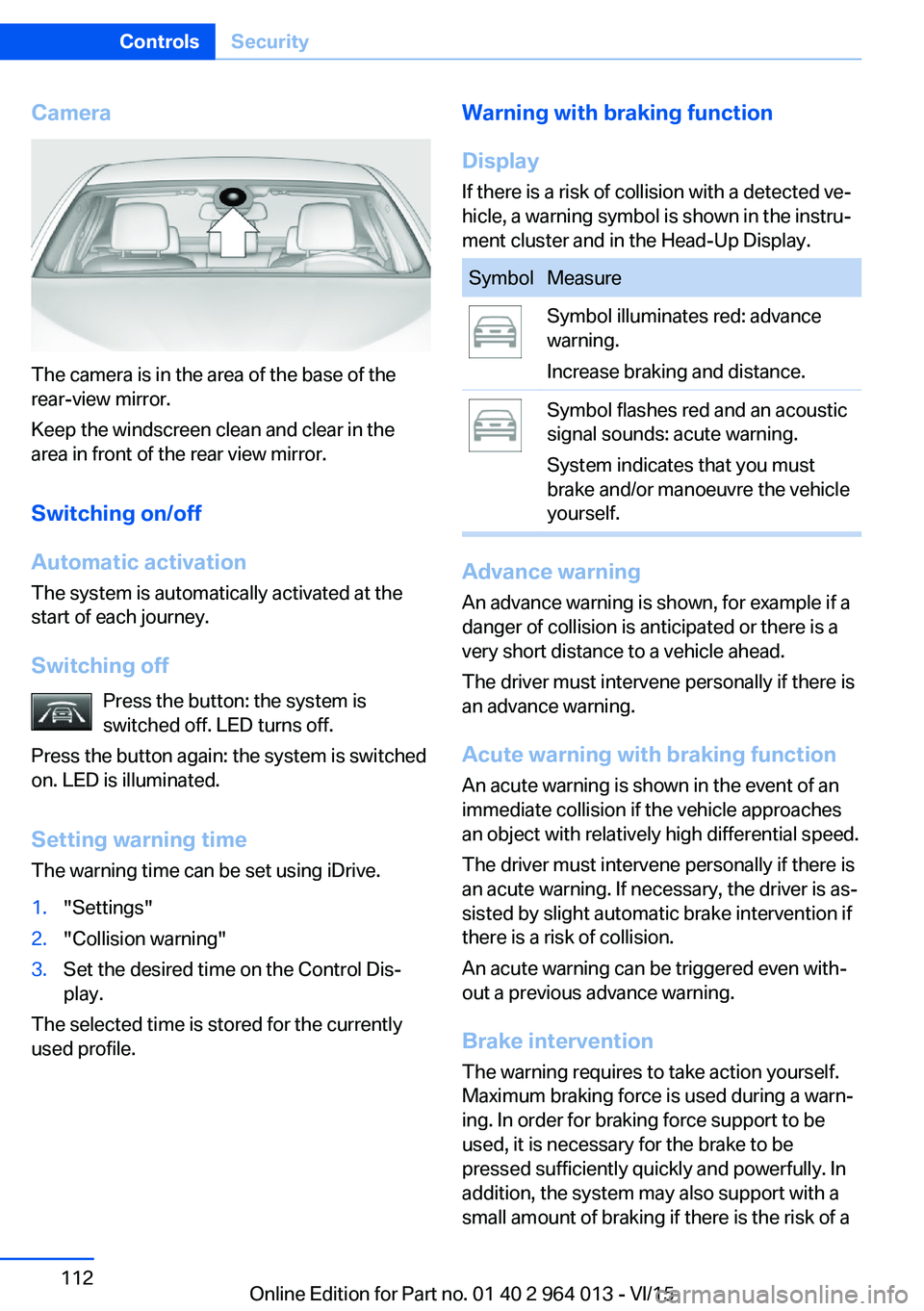
Camera
The camera is in the area of the base of the
rear-view mirror.
Keep the windscreen clean and clear in the
area in front of the rear view mirror.
Switching on/off
Automatic activation The system is automatically activated at the
start of each journey.
Switching off Press the button: the system is
switched off. LED turns off.
Press the button again: the system is switched
on. LED is illuminated.
Setting warning time
The warning time can be set using iDrive.
1."Settings"2."Collision warning"3.Set the desired time on the Control Dis‐
play.
The selected time is stored for the currently
used profile.
Warning with braking function
Display
If there is a risk of collision with a detected ve‐
hicle, a warning symbol is shown in the instru‐
ment cluster and in the Head-Up Display.SymbolMeasureSymbol illuminates red: advance
warning.
Increase braking and distance.Symbol flashes red and an acoustic
signal sounds: acute warning.
System indicates that you must
brake and/or manoeuvre the vehicle
yourself.
Advance warning
An advance warning is shown, for example if a
danger of collision is anticipated or there is a very short distance to a vehicle ahead.
The driver must intervene personally if there is
an advance warning.
Acute warning with braking function
An acute warning is shown in the event of an
immediate collision if the vehicle approaches
an object with relatively high differential speed.
The driver must intervene personally if there is
an acute warning. If necessary, the driver is as‐
sisted by slight automatic brake intervention if
there is a risk of collision.
An acute warning can be triggered even with‐
out a previous advance warning.
Brake interventionThe warning requires to take action yourself.
Maximum braking force is used during a warn‐
ing. In order for braking force support to be
used, it is necessary for the brake to be
pressed sufficiently quickly and powerfully. In
addition, the system may also support with a
small amount of braking if there is the risk of a
Seite 112ControlsSecurity112
Online Edition for Part no. 01 40 2 964 013 - VI/15
Page 132 of 228

Functional requirements
To ensure correct functionality:▷Do not cover sensors, for example by stick‐
ers, bicycle rack.▷Keep sensors clean and free from ice.
For cleaning: do not spray the sensors with
high-pressure cleaners for an extended period
of time and maintain a distance of at least
30 cm, 12 in.
Switching on/off
Automatic switching on While the engine is running, engage selector
lever position R.
Automatic switching off when moving forwards
The system switches off when a certain dis‐
tance or speed is exceeded.
Switch the system back on if necessary.
With front PDC: switching on/off
manually
Press the button.
▷On: LED is illuminated.▷Off: LED turns off.
Display
Audible warning signals An intermittent sound indicates position of an
object as the vehicle approaches it. For in‐
stance, if an object is identified to the rear left of the vehicle, the warning signal sounds from
the rear left loudspeaker.
The shorter the distance to an object be‐
comes, the shorter the intervals become.
If the distance to a detected object is less than
approximately 25 cm, 10 in, a continuous tone
sounds.
With front PDC: if there are objects in front of
and behind the vehicle, an alternating continu‐
ous tone sounds.
Volume control It is possible to set the ratio between the vol‐
ume of the PDC acoustic signal and the vol‐
ume of the Entertainment.1."Multimedia", "Radio" or "Settings"2."Sound"3."Volume settings"4."PDC"5.Turn the Controller until the desired set‐
ting is reached.6.Press the Controller.
The setting is saved for the currently used pro‐
file.
Visual warning
When the vehicle is approaching an object it
will be shown on the Control Display. Objects
that are further away from the vehicle will ap‐
pear on the Control Display before an acoustic
signal is given.
A display is superimposed as soon as PDC is
activated.
Recording range of sensors is shown in col‐
ours green, yellow and red.
If the reversing camera image is displayed, it is
possible to change over to PDC:
"Rear view camera"
System limits
Limits of the ultrasound measurement
Detection of objects might not be possible if
the limits of the physical ultrasound measure‐
ment are exceeded, such as for instance at the
following times:
▷With small children and animals.Seite 132ControlsDriving comfort132
Online Edition for Part no. 01 40 2 964 013 - VI/15
Page 163 of 228

General driving information
Closing the boot lid WARNING
An open boot lid projects beyond the ve‐
hicle, and in the event of an accident, braking
or avoidance manoeuvres, it can endanger ve‐ hicle occupants and other road users, or dam‐
age the vehicle. There is also the danger of ex‐
haust fumes entering the interior of the
vehicle. Danger of injury or damage to prop‐
erty. Do not drive with the boot lid open.◀
If there is no alternative to driving with the tail‐
gate open:▷Close all windows and the Glass Roof.▷Turn up the blower to a high output level.▷Maintain moderate speed.
Hot exhaust system
WARNING
During driving, high temperatures can be
generated under the body, for example be‐
cause of the exhaust system. If flammable ma‐
terials, for example leaves of grass, come into
contact with hot parts of the exhaust system,
these materials can catch fire. Danger of injury
or damage to property.
Never remove the heat shields fitted here, or
apply underseal to them. Make sure that when driving, idling or parking, no flammable materi‐
als can come into contact with hot vehicle
parts. Do not touch the hot exhaust system.◀
Radio signals WARNING
Certain vehicle functions may be affec‐
ted by interference from high-frequency radio
signals. Such signals are output from a series
of transmission systems, for example, from air
traffic beacons or relay stations for mobile tele‐
communications.
We recommend you consult a Service Partner
or a qualified specialist workshop should you
experience any difficulties.◀
Mobile communication equipment WARNING
The vehicle's electronics and mobile
radio devices can interfere. The transmission
operation of mobile radio devices generates
radiation. Danger of injury or damage to prop‐
erty. If possible, only use mobile radio devices,
e.g. mobile telephones, in the interior with di‐
rect connection to an external antenna to ex‐
clude mutual interference and to dissipate the
radiation from the vehicle's interior.◀
Aquaplaning
On wet or slushy roads, a wedge of water can
form between the tyres and the road.
This situation, known as aquaplaning, means
that the tyre can actually lose contact com‐
pletely with the road surface and the vehicle
can neither be steered nor the brakes properly
applied.
Wading ATTENTION
Driving through excessively deep water
too fast can result in water entering the engine
compartment, electrical system or transmis‐
sion. Danger of damage to property. When
driving through water, do not exceed the maxi‐
mum specified water depth and maximum
fording speed.◀
Only if the water is calm and only up to a water
depth of max. 25 cm, approximately 9.8 inches
and at this depth drive no faster than walking
speed up to 5 km/h, approximately 3 mph.
Safe braking Your vehicle is equipped with ABS as standard.Seite 163Driving precautionsDriving hints163
Online Edition for Part no. 01 40 2 964 013 - VI/15