Page 105 of 300

..... N
co ~ CX)
..... I.Cl U"I
..... I.Cl .....
Energy flow display
Applies to vehicles: with hybrid drive
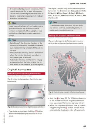
Fig . 112 Instrument cluster : ene rgy flow display
The energy flow of the hybrid system is shown in
the instrument cluster display and in the MMI
d isplay. The image is animated in the MMI dis
play.
Image in the instrument cluster display
.. Press the I RESET I button in the windsh ield wip
er lever repeatedly until the energy flow display
¢fig. 112 appears.
Component Color
@Combustion engine orange
gray
@ Propshaft green
orange
green-orange
gray
@ H
igh voltage battery green
green (animate d in
MMI)
gray
@ Movement arrow green
orange
green-orange
@ M
ovement arrow green
Hybrid
Fig. 113 MMI disp lay: energy flow d isplay
Image in the MMI display
.,. Select: I MEN u I fun ction button > Hybrid control
button
¢ fig. 113.
Meaning
The combustion engine is running
The comb ustion eng ine is off
Electric driv ing/recuperat ing
Driving with t he combustion engine
Driving with the combustion engine and electric
motor (boost)
Vehicle stationary/rolling in the N selector lever
position
High voltage battery charge level
High voltage battery is charging
Vehicle is not in drive ready mode
Electric driv ing
Dr iving w ith the combustion engine
Driving with the combustion engine and electric
motor (boost)
Recuperating
103
Page 106 of 300

Hybrid
@ Tips
The Energy flow display will not shown in the MMI display when the reverse gear is engag-
ed, due to safety reasons.
Consumption display
App lies to veh icles: w ith hybrid drive
Fig. 114 MMI disp lay : co nsum ption display
The consumption display shows the average en
ergy consumption and the recuperation quantity
in 5 minute intervals .
Calling up the consumption display
• Select : I MENU I function button> Hybrid control
button .
• Turn the control knob counter -clockwise.
Resetting the consumption display
• Select : I MENU I function button > Hybrid control
button.
• Turn the control knob to
Reset consumption
statistics.
The orange bars show the average consumption
and the green bars show the recuperation quanti
ty . Each bar represents a measured 5 minute in
terval. The display covers a
60 minute time peri
od .
The bar with the white border on the outer right shows the current average consumption or the
current recuperation quantity. After 5 minutes,
this bar travels a step to the left and a new bar
appears in the outer right.
The filled bars show the values for the current
drive cycle. Once the ignition is switched off and
on again, all of the previous bars are displayed as
104
not filled and new filled bars appear on the right.
This is so that the values from the previous trips
and the current trip can be compared visually .
Vehicle tool kit and tire repair set
Applies to vehicles: with hybrid drive
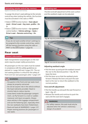
Fig. 115 Luggage compartmen t: v ehicle tool bag and tir e
repair set
The vehicle tool kit is found under a cover in the
cargo floor~
fig. 115 @. The tire repair set (Tire
Mobility System) is found in the storage com
partment in the right side trim panel @.
Additional information about the vehicle tool kit
may be found under~
page 254 and about the
tire repair set under
~page 257 .
@ Tips
The right storage compartment in the lug
gage compartment and its contents must al
ways be kept in the vehicle. The vehicle must
not be operated without the tire repair set .
Charging the batteries
Applies to vehicles: with hybrid drive
The vehicle is equipped with two 12 volt batteries
and a high voltage battery.
If the 12 volt batteries are dead , they may be
charged with a charger or the vehicle may be
jump started with assistance from another vehi
cle in the same way as a conventional vehicle.
The same applies to the high voltage battery if it
is discharged. However, in this case, the charging
process is accompanied with messages in the in
strument cluster display. The ignition must be
switched on and all unnecessary electric compo- nents must be turned off. ..,.
Page 107 of 300

.... N
co
er::
co
....
....
The connections in the engine compartment are
used for both charging and jump starting
¢ page 231 or¢ page 2 70.
Vehicle not ready to start. See owner's
manual
This message appears if the high voltage battery
charge level is too low. The vehicle can no longer
be started with its own power. The high voltage
battery must be charged with a charger or the ve
hicle must be jump started with the a id of anoth
er vehicle.
After the connecting the charger or jumper ca bles, the ignition must be turned off for approxi
mately two minutes and then turned on again.
After no more than one m inute, one of the fol
l owing indicator lights turns on in the instrument
cluster display .
B Charging battery. Please wait ...
If the indicator light turns on and this message
appears, the high voltage battery is charging or
the vehicle is be ing jump started with assistance
from another veh icle .
If the 12 volt batteries are dead, the -indi
cator light turns on . The charging procedure
takes longer in this case because the 12 volt bat
ter ies a re charged first. The procedure goes fast
er with the ignit ion switched off.
Vehicle ready to start.
This message appears if the charging procedure
was successful. The vehicle may be started again .
Battery could not be charged enough to start
vehicle.
This message appears if the charging procedure
was not successful or it was interrupted. This
may happen if the charger or the battery in the
veh icle that is assist ing is too weak. If the ve hicle
cannot be started, see an authorized repair facili
ty for ass istance.
(D Tips
- The charger should deliver a current of at
l east 30 A. Otherwise charging the high
voltage battery will take considerably Ion-
Hybrid
ger . A current between 50 A and 70 A is ide
al.
- The vehicle that is assisting should be some
what within the same vehicle class when
jump starting a vehicle. A smaller vehicle's
battery may be drained.
- After approximately 30 minutes, the charg
ing procedure ends because the ignition is
automatically turned off. If you wou ld like
to cont inue to charge the battery, turn the
ign ition on again .
Vehicle transport
App lies to vehicles: wit h hybrid drive
The following contains information you should
know about transporting your vehicle.
The lithium ion battery (SANYO 72 UF 121 285)
installed in your vehicle has passed test 38.3 in
accordance with UN handbook tests and criter ia.
The vehicle may be transported with the battery
installed as conventional class 9 hazardous mate
rials without addit ional officia l consent for a ir
and sea transportation (current law ICAO- TI and
IMDG-Code 01.01.2012).
105
Page 108 of 300

Audi adaptive cruise control and braking guard
Audi adaptive cruise
control and braking
guard
Introduction
Applies to vehicles: with Audi adaptive cruise contro l
The adaptive cruise contro l system assists the
driver by regulating vehicle speed and helping to
maintain a set distance to the veh icle ahead ,
within the limits of the system. If the system de
tects a moving vehicle up ahead, adaptive cruise
control can brake and then accelerate your vehi
cle. This helps to make driving more comfortable
on long highway stretches.
The braking guard system can warn you about an
impending collision and initiate braking maneu
vers
c::> page 112.
Adaptive cruise control and braking guard have
technical limitations that you must know, so
please read th is section carefully, understand
how the system works and use them properly at
all times.
General information
General information
Applies to veh icles: with Audi adaptive cruise control
Fig. 116 Front of t he veh icle: Posit ion of radar sensor
The area that contains the radar sensor
c::> fig . 116 must never be covered by st ickers or
other objects or obstructed with dirt, insects,
snow or ice that w ill interfere w ith the adaptive
cruise control system and braking guard. For in
formation on cleaning, refer to
c::> page 207. The
same appl ies for any modifications made in the
front area .
106
The function of the adaptive cruise control sys
tem and braking guard is limited under some
condit ions:
- Objects can only be detected when they are
within sensor range
<:!) page 108, fig . 119.
-The system has a limited ability to detect ob
jects that are a short distance ahead, off to the
side of your vehicle or moving into your lane.
- Some k inds of veh icles are hard to detect; for
example motorcycles, veh icles with high
ground clearance or overhanging loads may be
detected when it is too late or they may not be
detected at all.
- When driving through curves ¢
page 107.
- Stationary objects i::!) page 107.
& WARNING
-Always pay attention to traffic when adaptive
cruise control is switched on and braking
guard is active. As the driver, you are still re
sponsible for starting and for maintaining
speed and distance to other objects . Braking
guard is used to assist you . The driver must
a lways take action to avoid a collision . The
driver is always responsible fo r braking at the
correct time.
- Improper use of adaptive cruise contro l can
cause collisions, other accidents and serious
personal injury.
- Never let the comfort and convenience that
adapt ive cr uise control and braking guard
offe r dist ract you from the need to be alert
to traffic cond itions and the need to remain
in full control of your ve hicle at all times,
- Always remember that the adaptive cruise
control and braking guard have limits -they
will not slow the vehicle down or maintain
the set distance when you dr ive towards an
obstacle or something on or near the road
that is not moving, such as vehicles stopped
in a traff ic jam, a stalled or disab led veh icle.
If registered by the radar sensor, veh icles o r
obstacles that are not moving can trigger a
coll ision warning and if confirmed by the
video camera, an acute collision warning. ..,
Page 109 of 300

..... N
co ~ CX)
..... I.Cl U"I
..... I.Cl .....
Audi ada pti ve c ruise contr ol and br akin g gu ard
-For safety reasons, do not use adapt ive
cruise contro l when driv ing on roads with
many curves, when the road surface is in
poor condit ion and/or in bad weather (such
as ice, fog, gravel, heavy rain and hydroplan
ing) . Us ing the system under these condi
t ions could result in a collision .
- Switch adaptive cruise contro l off tempora
rily when driving in turn ing lanes, on ex
pressway exits or in const ruc tion zones. This
preven ts the vehicle from accelerating to
the set speed when in these situat ions .
- T he adapt ive cr uise con trol system will no t
br ake by i tself if you pu t your foot on the ac
celerator peda l. Doing so can override the
speed and distance regulation.
- Whe n approaching stat ionary obje cts such
as stopped traffic, adapt ive cruise control
will not respo nd and braking guard will have
limited function .
- The adaptive cruise control system and
brak ing guard do not react to peop le, ani
ma ls, objects crossing the road or oncom ing
objects.
- The function of the radar sensor can be af
fected by reflective objects such as guard
rai ls, t he entrance to a tunnel, heavy rain or
ice.
- Never follow a veh icle so closely that you
cannot stop your vehicle safely . The adap
t ive cr uise control cannot slow or brake the
vehicle safely when you follow another veh i
cle too close ly. Always remember th at the
au tom atic b raking function ca nnot br ing the
vehicle to a sudden or emergency stop un
der these conditions .
- T o preven t unintended operation, always
switch adaptive cruise co ntro l off w hen it is
not being used .
(D Note
The sensor can be disp laced by im pacts o r
d amage to the bumper, whee l housing and
underbody. That cou ld affect the adaptive
cru ise control system and braking guard.
Have your a uthorized Audi dea ler or author
ized Audi Service Fac ility check their function.
In curves
App lies to vehicles: with A udi adapt ive cr uise control
Fig. 117 Ex amp le : d ri ving int o a c urve
When driving into a curve¢ fig. 117 and out of a
curve, the adapt ive cruise control may react to a
vehicle in the next lane and apply the brakes . Yo u
can override or prevent the b raking by press ing
the accelerator pedal b riefly.
Stationary objects
Applies to vehicles: wit h Audi adaptive c ruise control
Fi g. 1 18 Example: object c hang ing lanes a nd st ationary
ob ject
The adaptive cruise control system only reacts to
objects that are moving or that the system has
already detected as moving. For example, if ave
hicle @, which has already been detected by the
adaptive cruise control, turns or changes lanes
and another stat ionary vehicle @ is located in
front of that vehicle, the system will not react to
t h e stationary veh icle.
107
Page 110 of 300

Audi adaptive cruise control and braking guard
Audi adaptive cruise
control
Description
A pplies to veh icles: with Audi adaptive cruise co ntrol
F ig. 119 Detection range
What can adaptive cruise control do?
The adaptive cruise control works in conjunct ion
with a radar sensor installed in the front of the
veh icle¢
page 106, fig. 116, which is subject to
designated system limits
¢page 108. Stationary
objects a re disregarded.
On open roads with no traffic, adaptive cru ise
control works like a regular cruise control sys
tem. The stored speed is ma inta ined. When ap
proaching a moving vehicle detected up ahead,
the adaptive cruise control system automatically
slows down to match that vehicle's speed and
then maintains the distance that the driver previ
ously stored. As soon as the system does not de
tect a vehicle up ahead, adaptive cruise control accelerates back up to the stored speed.
Which functions can be controlled?
When you switch adaptive cruise control on, you
can set the current speed as the "control speed"
¢ page 108, Switching on and off.
When driving, you can stop cruise control
¢
page 110 or change the speed ¢ page 109 at
any time.
You can also set the distance to the object ahead
and set the adaptive cruise control driving pro
gram
¢page 110.
108
Switch ing on and off
App lies to vehicles: wit h Audi ada ptive cruise control
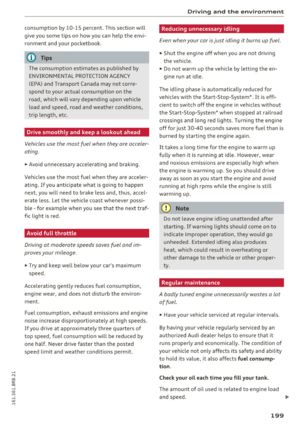
Fig. 120 Selector lever: switch ing on/o ff
Fig. 121 Instrument cl uster: adapt ive c ruise control
You can set any speed between 20 mph and
95 mph (30 and 150 km/h) .
Indicator lamps and messages in the instrument cluster display inform you about the current sys
tem status and settings .
Switching adaptive cruise control on
.,. Pull the lever toward you into position (D
¢ fig. 120. ACC: Standby appears in the instru
ment cluster display.
Setting the speed and activating regulation
.,. To set the current speed, press the ISETI button
¢
fig. 120. The set speed is shown in the tach
ometer @and is also shown briefly in the dis
play @¢
fig. 121 .
Switching adaptive cruise control off
.,. Push the lever away from you into position @
until it clicks into place. The message ACC: Off
appears. Iii>
Page 111 of 300

..... N
co ~ CX)
..... I.Cl U"I
..... I.Cl .....
Audi adaptive cruise control and braking guard
@ Indicator lights
Ill-Adaptive cru ise control is switched on. No
vehicles are detected up ahead. The stored speed
is maintained.
• -A moving vehicle is detected up ahead. The
adaptive cruise control system regulates the
speed and distance to the moving vehicle ahead
and accelerates/brakes automatically.
• -When automatic braking is not ab le to keep
enough distance to a previously detected moving
vehicle up ahead, you must take control and
brake
~ page 111, Request for driver interven
tion.
© Display
If adaptive cruise control is not shown in the dis
play, you can call it up with the
I RESETI button
¢page 20.
Based on the symbols in the display, you can de
termine if the system is maintaining a distance to
the vehicle ahead and what that distance is.
No vehicle -No vehicle ahead was detected.
White vehicle -A vehicle ahead was detected.
Red vehicle -Prompt for the dr iver to take action
¢page 111.
Both arrows on the scale © indicate the distance
to the vehicle ahead . No arrow appears when the
vehicle is on an open road and there is no object
ahead . If an object is detected ahead, the arrow
moves on the scale .
The green zone on the scale shows the stored dis
tance. For information on changing the stored
distance, refer to
¢page 110. If the distance se
lected is too close or may soon become too close,
the arrows move into the red zone on the scale.
A WARNING
Improper use of the adaptive cruise control
can cause collis ions, other acc idents and seri
ous personal injur ies.
- Pressing the
!SET ! button when driving at
speeds below 20 mph (30 km/h), will auto
matically accelerate the vehicle to 20 mph (30
km/h), which is the minimum speed
that can be set.
(D Tips
- If you switch the ignition or the adaptive
cruise control off, the set speed is erased
from the system memory.
- Th e Electronic Stabilization Control (ESC) is
automatically turned on when the adaptive
cruise control is turned on . You cannot
switch the ESC into offroad mode while the
adaptive cru ise control is turned on
¢page 191.
Changing the speed
Applies to vehicles: with Audi adapt ive cru ise control
0
f
•
0
Fig. 122 Selector lever: ch an gin g the speed
.,. To increase or reduce the speed in increments,
tap the lever up or down.
" To increase or reduce the speed quickly,
hold
the lever up or down until the red LED @ reach
es the des ired speed c::>
page 108, fig. 121 .
Following any changes, the new stored speed will
be displayed br iefly in the display @c::>
page 108,
fig. 121 .
109
Page 112 of 300

Audi adaptive cruise control and braking guard
Interrupting cruise control
Applies to vehicles: with Audi adaptive cruise contro l
Fig. 123 Selector leve r
Requirement: adaptive cruise control must be
switched on
c:> fig . 123 (D.
Overriding cruise control
• To accelerate manually , press the accelerator
pedal. The message
ACC: override appears .
• To resume adaptive cruise control, remove your
foot from the gas pedal. The system re turns
again to the speed that was saved before .
• You can
save a new speed at any time by press
ing the
IS ETI button c:> fig. 123 .
Canceling cruise control while driving
• Move the lever into position @. The message
ACC: Standby appears. Or
• press the brake pedal.
• To resume the stored speed, move the lever in
to position
@.
.,&. WARNING
Never resum e the stored speed if the speed is
too high for prevailing road, traffic or weather
conditions.
110
Setting the distance
Applies to vehicles: with Audi adaptive cruise control
Fig. 124 Se lector leve r: setting the distance
• Tap the switch to display the current set dis
tance
c:> fig . 124 .
• To increase or reduce the distance by incre
ments, tap the switch again to the left or right.
The distance between the two veh icles will
change in the instrument cluster display .
When approaching a moving vehicle up ahead,
the adapt ive cruise control system b rakes to
match that object's speed and then maintains
the stored distance.
If the vehicle ahead acceler
ates, adaptive cruise control will also accelerate
up to the stored speed .
The higher the speed, the greater the distance in
yards (meters)
c:> &. . The Distance 3 setting is
recommended.
The distances provided are spec ified values . De
pending on the driving situation and the how the
vehicle ahead is driving, the actua l distance may
be more or less than these target distances .
The var ious symbo ls for the time increments ap
pear briefly in the information line @
c:>page 108, fig . 121 when yo u change the set
tings.
c::::, _c::::, ___ Distance 1 : This setting cor responds
to a distance of 92 feet/28 meters when travel
in g at 62 mph (100 km/h), or a time interval of 1
second .
c::::, __ c::::, __ Distanc e 2: This setting corresponds
to a distance of 118 feet/36 meters when travel
in g at 62 mph (100 km/h), or a time interval of
1.3 seconds .