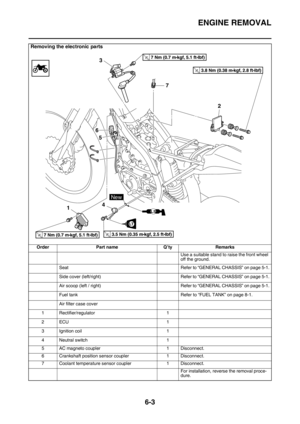
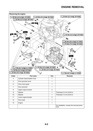
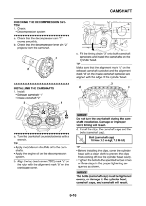
Page 409 of 430

ELECTRICAL COMPONENTS
9-75
▼▼▼▼▼▼▼▼▼▼▼▼▼▼▼▼▼▼▼▼▼▼▼▼▼▼▼▼▼▼▼▼
a. Connect the pocket tester ( 100) to the
crankshaft position sensor coupler.
b. Measure the crankshaft position sensor re-
sistance.
▲▲▲▲▲▲▲▲▲▲▲▲▲▲▲▲▲▲▲▲▲▲▲▲▲▲▲▲▲▲▲▲
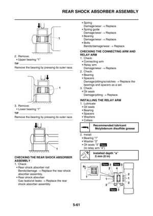
EAS2GB2394CHECKING THE LEAN ANGLE SENSOR
1. Remove:
• Lean angle sensor
(from the bracket)
2. Check:
• Lean angle sensor out put voltage
Out of specification Replace.
▼▼▼▼▼▼▼▼▼▼▼▼▼▼▼▼▼▼▼▼▼▼▼▼▼▼▼▼▼▼▼▼
a. Connect the lean angle sensor coupler to
the wire harness.
b. Connect the pocket tester (DC 20 V) to the lean angle sensor coupler as shown.
c. Incline the lean angle sensor.
d. Measure the lean angle sensor out put volt-
age.
▲▲▲▲▲▲▲▲▲▲▲▲▲▲▲▲▲▲▲▲▲▲▲▲▲▲▲▲▲▲▲▲
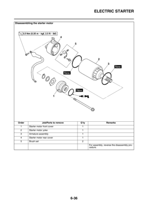
EAS2GB2395CHECKING THE STARTER MOTOR OPERA-
TION
1. Check:
• Coolant temperature sensor
Does not operate Perform the electric
starting system troubleshooting, starting
with step 4.
Refer to “ELECTRIC STARTING SYSTEM”
on page 9-6.
▼▼▼▼▼▼▼▼▼▼▼▼▼▼▼▼▼▼▼▼▼▼▼▼▼▼▼▼▼▼▼▼
a. Connect the positive battery terminal “1” and
starter motor lead “2” with a jumper lead “3”.
EWA
WARNING
• Handle the coolant temperature sensor
with special care.
• Never subject the coolant temperature
sensor to strong shocks. If the coolant
temperature sensor is dropped, replace it. Crankshaft position sensor resis-
tance
228–342 (Gy–B)
Pocket tester
90890-03112
Analog pocket tester
YU-03112-C
• Positive tester probe
Gray “1”
• Negative tester probe
Black “2”
Lean angle sensor out put voltage
Less than 45° “a”
0.4–1.4V
More than 45° “b”
3.7–4.4V
12
Gy B
Pocket tester
90890-03112
Analog pocket tester
YU-03112-C
Test harness– lean angle sensor
(6P)
90890-03209
Test harness– lean angle sensor
(6P)
YU-03209
• Positive tester probe
Yellow/Green “1”
• Negative tester probe
Black/Blue “2”
2 1
aa
bON ON
Page 410 of 430

ELECTRICAL COMPONENTS
9-76
b. Check the starter motor operation.
▲▲▲▲▲▲▲▲▲▲▲▲▲▲▲▲▲▲▲▲▲▲▲▲▲▲▲▲▲▲▲▲
EAS28150CHECKING THE STATOR COIL
1. Disconnect:
• Stator coil coupler
(from the wire harness)
2. Check:
• Stator coil resistance
Out of specification Replace the stator
coil.
▼▼▼▼▼▼▼▼▼▼▼▼▼▼▼▼▼▼▼▼▼▼▼▼▼▼▼▼▼▼▼▼
a. Connect the pocket tester ( 1) to the sta-
tor coil coupler as shown.b. Measure the stator coil resistance.
▲▲▲▲▲▲▲▲▲▲▲▲▲▲▲▲▲▲▲▲▲▲▲▲▲▲▲▲▲▲▲▲
EAS2GB2396CHECKING THE RECTIFIER/REGULATOR
1. Check:
• Charging voltage
Out of specification Replace the rectifier/
regulator.
▼▼▼▼▼▼▼▼▼▼▼▼▼▼▼▼▼▼▼▼▼▼▼▼▼▼▼▼▼▼▼▼
a. Set the digital tachometer to the ignition coil.
b. Connect the pocket tester (DC 20 V) to the
rectifier/regulator coupler as shown.
c. Start the engine and let it run at approxi-
mately 5000 r/min.
d. Measure the charging voltage.
▲▲▲▲▲▲▲▲▲▲▲▲▲▲▲▲▲▲▲▲▲▲▲▲▲▲▲▲▲▲▲▲
Stator coil resistance
0.528–0.792 (W–W)
Pocket tester
90890-03112
Analog pocket tester
YU-03112-C
• Positive tester probe
White “1”
• Negative tester probe
White “2”
• Positive tester probe
White “1”
• Negative tester probe
White “3”
• Positive tester probe
White “2”
• Negative tester probe
White “3”
Charging voltage
14 V at 5000 r/min
Pocket tester
90890-03112
Analog pocket tester
YU-03112-C
• Positive tester probe
Red “1”
• Negative tester probe
Black “2”
123
12
Page 411 of 430

ELECTRICAL COMPONENTS
9-77
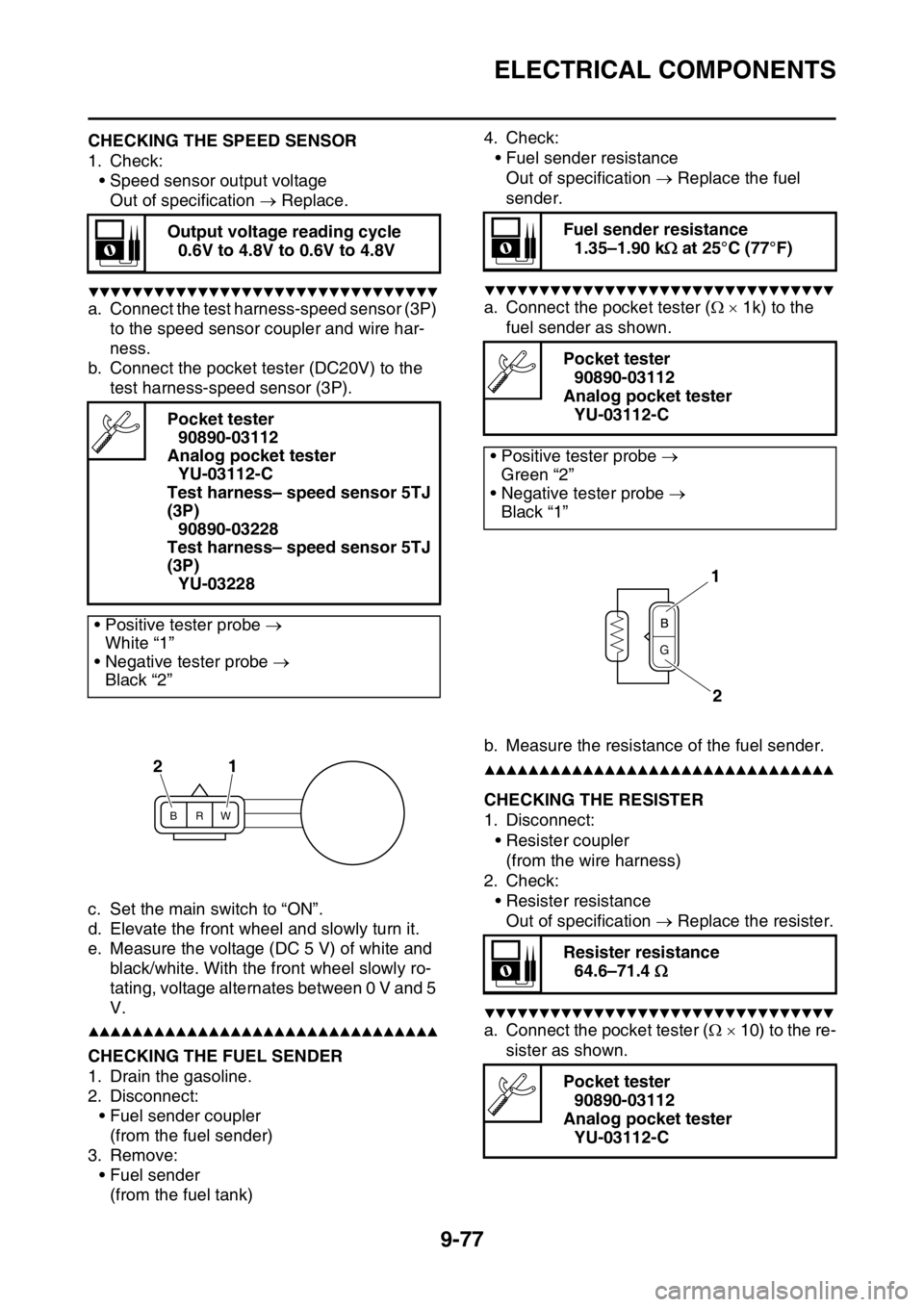
EAS2GB2397CHECKING THE SPEED SENSOR
1. Check:
• Speed sensor output voltage
Out of specification Replace.
▼▼▼▼▼▼▼▼▼▼▼▼▼▼▼▼▼▼▼▼▼▼▼▼▼▼▼▼▼▼▼▼
a. Connect the test harness-speed sensor (3P)
to the speed sensor coupler and wire har-
ness.
b. Connect the pocket tester (DC20V) to the
test harness-speed sensor (3P).
c. Set the main switch to “ON”.
d. Elevate the front wheel and slowly turn it.
e. Measure the voltage (DC 5 V) of white and
black/white. With the front wheel slowly ro-
tating, voltage alternates between 0 V and 5
V.
▲▲▲▲▲▲▲▲▲▲▲▲▲▲▲▲▲▲▲▲▲▲▲▲▲▲▲▲▲▲▲▲EAS2GB2398CHECKING THE FUEL SENDER
1. Drain the gasoline.
2. Disconnect:
• Fuel sender coupler
(from the fuel sender)
3. Remove:
• Fuel sender
(from the fuel tank)4. Check:
• Fuel sender resistance
Out of specification Replace the fuel
sender.
▼▼▼▼▼▼▼▼▼▼▼▼▼▼▼▼▼▼▼▼▼▼▼▼▼▼▼▼▼▼▼▼
a. Connect the pocket tester ( 1k) to the
fuel sender as shown.
b. Measure the resistance of the fuel sender.
▲▲▲▲▲▲▲▲▲▲▲▲▲▲▲▲▲▲▲▲▲▲▲▲▲▲▲▲▲▲▲▲
EAS2GB2399CHECKING THE RESISTER
1. Disconnect:
• Resister coupler
(from the wire harness)
2. Check:
• Resister resistance
Out of specification Replace the resister.
▼▼▼▼▼▼▼▼▼▼▼▼▼▼▼▼▼▼▼▼▼▼▼▼▼▼▼▼▼▼▼▼
a. Connect the pocket tester ( 10) to the re-
sister as shown. Output voltage reading cycle
0.6V to 4.8V to 0.6V to 4.8V
Pocket tester
90890-03112
Analog pocket tester
YU-03112-C
Test harness– speed sensor 5TJ
(3P)
90890-03228
Test harness– speed sensor 5TJ
(3P)
YU-03228
• Positive tester probe
White “1”
• Negative tester probe
Black “2”
BRW
21
Fuel sender resistance
1.35–1.90 k at 25°C (77°F)
Pocket tester
90890-03112
Analog pocket tester
YU-03112-C
• Positive tester probe
Green “2”
• Negative tester probe
Black “1”
Resister resistance
64.6–71.4
Pocket tester
90890-03112
Analog pocket tester
YU-03112-C
1
2
Page 412 of 430

ELECTRICAL COMPONENTS
9-78
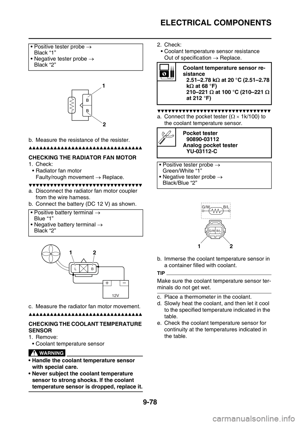
b. Measure the resistance of the resister.
▲▲▲▲▲▲▲▲▲▲▲▲▲▲▲▲▲▲▲▲▲▲▲▲▲▲▲▲▲▲▲▲
EAS2GB2400CHECKING THE RADIATOR FAN MOTOR
1. Check:
• Radiator fan motor
Faulty/rough movement Replace.
▼▼▼▼▼▼▼▼▼▼▼▼▼▼▼▼▼▼▼▼▼▼▼▼▼▼▼▼▼▼▼▼
a. Disconnect the radiator fan motor coupler
from the wire harness.
b. Connect the battery (DC 12 V) as shown.
c. Measure the radiator fan motor movement.
▲▲▲▲▲▲▲▲▲▲▲▲▲▲▲▲▲▲▲▲▲▲▲▲▲▲▲▲▲▲▲▲
EAS2GB2401CHECKING THE COOLANT TEMPERATURE
SENSOR
1. Remove:
• Coolant temperature sensor
EWA
WARNING
• Handle the coolant temperature sensor
with special care.
• Never subject the coolant temperature
sensor to strong shocks. If the coolant
temperature sensor is dropped, replace it.2. Check:
• Coolant temperature sensor resistance
Out of specification Replace.
▼▼▼▼▼▼▼▼▼▼▼▼▼▼▼▼▼▼▼▼▼▼▼▼▼▼▼▼▼▼▼▼
a. Connect the pocket tester ( 1k/100) to
the coolant temperature sensor.
b. Immerse the coolant temperature sensor in
a container filled with coolant.
TIP
Make sure the coolant temperature sensor ter-
minals do not get wet.
c. Place a thermometer in the coolant.
d. Slowly heat the coolant, and then let it cool
to the specified temperature indicated in the
table.
e. Check the coolant temperature sensor for
continuity at the temperatures indicated in
the table. • Positive tester probe
Black “1”
• Negative tester probe
Black “2”
• Positive battery terminal
Blue “1”
• Negative battery terminal
Black “2”
1
2
12
12V
LB
Coolant temperature sensor re-
sistance
2.51–2.78 k at 20 °C (2.51–2.78
k at 68 °F)
210–221 at 100 °C (210–221
at 212 °F)
Pocket tester
90890-03112
Analog pocket tester
YU-03112-C
• Positive tester probe
Green/White “1”
• Negative tester probe
Black/Blue “2”
12
G/W B/L
B/L G/W
Page 413 of 430

ELECTRICAL COMPONENTS
9-79
▲▲▲▲▲▲▲▲▲▲▲▲▲▲▲▲▲▲▲▲▲▲▲▲▲▲▲▲▲▲▲▲
EAS2GB2402CHECKING THE THROTTLE POSITION
SENSOR
1. Remove:
• Throttle position sensor
(from the throttle body)
EWA
WARNING
• Handle the throttle position sensor with
special care.
• Never subject the throttle position sensor
to strong shocks. If the throttle position
sensor is dropped, replace it.
2. Check:
• Throttle position sensor maximum resis-
tance
Out of specification Replace.
▼▼▼▼▼▼▼▼▼▼▼▼▼▼▼▼▼▼▼▼▼▼▼▼▼▼▼▼▼▼▼▼
a. Connect the pocket tester ( 1k) to the
throttle position sensor.b. Check the throttle position sensor maximum
resistance.
▲▲▲▲▲▲▲▲▲▲▲▲▲▲▲▲▲▲▲▲▲▲▲▲▲▲▲▲▲▲▲▲
3. Install:
• Throttle position sensor
TIP
When mounting the throttle position sensor, ad-
just its angle properly. Refer to “ADJUSTING
THE THROTTLE POSITION SENSOR” on
page 8-11.
EAS2GB2403CHECKING THE THROTTLE POSITION
SENSOR INPUT VOLTAGE
1. Check:
• Throttle position sensor input voltage
Out of specification Replace the ECU.
▼▼▼▼▼▼▼▼▼▼▼▼▼▼▼▼▼▼▼▼▼▼▼▼▼▼▼▼▼▼▼▼
a. Connect the test harness S-pressure sensor
(3P) to the throttle position sensor coupler
and the wire harness.
b. Connect the pocket tester (20 VDC) to the
test harness S-pressure sensor (3P). Resistance
6.30 k
Pocket tester
90890-03112
Analog pocket tester
YU-03112-C
• Positive tester probe
Blue “1”
• Negative tester probe
Black/Blue “2”
Throttle position sensor input
voltage
4–6 V
Pocket tester
90890-03112
Analog pocket tester
YU-03112-C
Test harness S– pressure sensor
(3P)
90890-03207
Test harness S– pressure sensor
(3P)
YU-03207
21
Page 414 of 430

ELECTRICAL COMPONENTS
9-80
c. Start the engine.
d. Measure the throttle position sensor input
voltage.
▲▲▲▲▲▲▲▲▲▲▲▲▲▲▲▲▲▲▲▲▲▲▲▲▲▲▲▲▲▲▲▲
EAS2GB2404CHECKING THE INTAKE AIR PRESSURE
SENSOR
1. Check:
• Intake air pressure sensor output voltage
Out of specification Replace.
▼▼▼▼▼▼▼▼▼▼▼▼▼▼▼▼▼▼▼▼▼▼▼▼▼▼▼▼▼▼▼▼
a. Connect the pocket tester (20 VDC) to the
intake air pressure sensor coupler (wire har-
ness side).b. Start the engine.
c. Measure the intake air pressure sensor out-
put voltage.
▲▲▲▲▲▲▲▲▲▲▲▲▲▲▲▲▲▲▲▲▲▲▲▲▲▲▲▲▲▲▲▲
EAS2GB2405CHECKING THE INTAKE AIR TEMPERA-
TURE SENSOR
1. Remove:
• Intake air temperature sensor
(from the air filter case)
EWA
WARNING
• Handle the intake air temperature sensor
with special care.
• Never subject the intake air temperature
sensor to strong shocks. If the intake air
temperature sensor is dropped, replace it.
2. Check:
• Intake air temperature sensor resistance
Out of specification Replace.
▼▼▼▼▼▼▼▼▼▼▼▼▼▼▼▼▼▼▼▼▼▼▼▼▼▼▼▼▼▼▼▼
a. Connect the pocket tester ( 1k/100) to
the intake air temperature sensor terminal. • Positive tester probe
Blue “1”
• Negative tester probe
Black/Blue “2”
Intake air pressure sensor output
voltage
3.61–3.67 V at 101.3 kPa (3.61–
3.67 V at 1.01kgf/cm
2, 3.61–3.67
V at 14.7 psi)
Pocket tester
90890-03112
Analog pocket tester
YU-03112-C
• Positive tester probe
Pink “1”
• Negative tester probe
Black/Blue “2”
21
Intake air temperature sensor re-
sistance
290–390 at 80 °C (290–390
176 °F)
Pocket tester
90890-03112
Analog pocket tester
YU-03112-C
• Positive tester probe
Brown/White “1”
• Negative tester probe
Black/Blue “2”
12
Page 415 of 430
ELECTRICAL COMPONENTS
9-81
▲▲▲▲▲▲▲▲▲▲▲▲▲▲▲▲▲▲▲▲▲▲▲▲▲▲▲▲▲▲▲▲
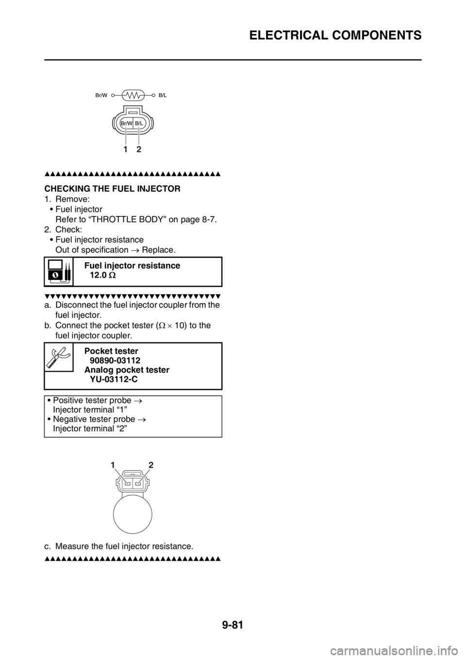
EAS2GB2406CHECKING THE FUEL INJECTOR
1. Remove:
• Fuel injector
Refer to “THROTTLE BODY” on page 8-7.
2. Check:
• Fuel injector resistance
Out of specification Replace.
▼▼▼▼▼▼▼▼▼▼▼▼▼▼▼▼▼▼▼▼▼▼▼▼▼▼▼▼▼▼▼▼
a. Disconnect the fuel injector coupler from the
fuel injector.
b. Connect the pocket tester ( 10) to the
fuel injector coupler.
c. Measure the fuel injector resistance.
▲▲▲▲▲▲▲▲▲▲▲▲▲▲▲▲▲▲▲▲▲▲▲▲▲▲▲▲▲▲▲▲
Fuel injector resistance
12.0
Pocket tester
90890-03112
Analog pocket tester
YU-03112-C
• Positive tester probe
Injector terminal “1”
• Negative tester probe
Injector terminal “2”
12
12
Page 416 of 430
ELECTRICAL COMPONENTS
9-83