Page 89 of 220

CAUTION■When closing the boot lid, jamming and damage to the cover or the side trim
panel can occur if handled incorrectly. The following guidelines must be ob-
served. ■ The holders B
on the cover must be resting completely on the pins
C
on
the side panel » Fig. 100.
■ The items which are transported must not exceed the height of the cover.
■ The cover must not be jammed in the surrounding seal of the luggage com-
partment lid when it is in the raised position. ■ There must be no object in the gap between the cover in the raise position
and the rear backrest.
Other positions of the luggage compartment cover
Fig. 101
Luggage compartment cover: stowed behind the rear seats/in
the lower position
Read and observe
and on page 84 first.
The luggage compartment cover can be placed in the following positions:
» Fig. 101
Behind the rear seat backrests
In the lower position
Store cover in the lower position
›
Press the top of the cover in the arrow direction » Fig. 101 -
.
In the front area, slots
B
» Fig. 100 on page 86 on the cover must be fully en-
gaged with the bolts on the side trim. In the back, the cover must be secured
at both ends under the latching.
In the lower position, the cover is designed for storing small objects up to a
weight of 2.5 kg in total.
Roll-up coverFig. 102
Roll-up cover: Pull out/roll/remove
Read and observe
and on page 84 first.
Pulling out
›
Grasp the cover on the handle
A
and pull it out in the direction of the arrow
1
until it clicks » Fig. 102.
Rolling up
›
Push the cover in the area of handle
A
in the direction of the arrow
2
» Fig. 102 .
The cover rolls up automatically.
Removing
The fully rolled luggage compartment cover can be removed.
›
Press on the side of the cross bar in the direction of arrow
3
and remove
the cover in the arrow direction
4
» Fig. 102 .
Inserting
›
First insert the cover on the left side.
›
Press on the side of the cross bar in the direction of arrow
3
and insert the
cover against arrow direction
4
» Fig. 102 .
WARNINGNo objects should be placed on the foldable boot cover. This could endan-
ger the vehicle occupants during sudden braking or vehicle impact.87Transporting and practical equipment
Page 90 of 220

Storage compartments under the floorFig. 103
Fold the floor back / storage compartment under the floor
Read and observe
and on page 84 first.
The storage compartment is located under the luggage compartment floor
» Fig. 103 -
.
›
Lift the rear portion of the floor and fold forward in the direction of arrow
» Fig. 103 -
.
The storage compartment is designed for storing small objects of up to 15 kg. in weight in total.
CAUTION
■ The following instructions must be observed to avoid damage to the storage
compartment. ■ Do not store any sharp objects in the storage compartment.
■ Place the items carefully into the storage compartment.
■ Do not place pressure on any points in the storage compartment.Cargo elementFig. 104
Removing cargo element/example on how to mount the load by
means of the cargo element
Read and observe
and on page 84 first.
The Cargo element can be stored under the floor in the boot.
The cargo element is designed for attaching and securing objects with a maxi-
mum total weight of 8 kg.
Usage of Cargo element
›
Remove the cargo element in the direction of arrow » Fig. 104 -
.
›
The Cargo element with Velcro element allows fastening near the rear seats
on the floor of the luggage compartment » Fig. 104 -
.
Flexible storage compartment
Fig. 105
Flexible storage compartment
Read and observe and on page 84 first.
The flexible storage compartment can be installed on either side of the boot
» Fig. 105 .
88Operation
Page 91 of 220

The storage compartment is designed for storing small objects with a maxi-
mum total weight of 8 kg.
Fitting›
Place both ends of the storage compartment into the openings on the right
side panel of the boot.
›
Push the storage compartment down to lock it.
Removing
›
Grasp the storage compartment on the two upper corners.
›
Remove the storage compartment by pulling upwards and then towards you.
Class N1 vehicles
Read and observe
and on page 84 first.
In class N1 vehicles that are not fitted with a protective grille, a lashing set that
complies with the EN 12195 standard (1-4) must be used for fastening the load.
Proper functioning of the electrical installation is essential for safe vehicle op-
eration. It is important to ensure that the electrical installation is not damaged
during the adjustment process or when the storage area is being loaded and
unloaded.
Variable loading floor in the luggage compartment
Introduction
This chapter contains information on the following subjects:
Setting in the upper position
89
Setting in the lower position
90
Removing/inserting
90
Folding / Securing
91
The maximum permissible load of the variable loading floor is 75 kg. For the
transport of heavy loads, adjust the variable loading floor to the lower position
or remove it from the vehicle.
Setting in the upper positionFig. 106
Set the variable loading floor to the upper position
The variable loading floor in the lower position can be set to the upper position
as follows.
›
Grasp the variable loading floor at handle
A
» Fig. 106 .
›
Lift the variable loading floor in the direction of arrow
1
and move partially
backwards in the direction of arrow
2
.
›
Lift the variable loading floor in the front area and place on edge
C
.
›
Insert the variable loading floor into slots
B
up to the stop in the direction of
arrow
3
.
›
Place the variable loading floor in the direction of arrow
4
.
Note
When in the upper position, there is space for storing items underneath the
variable loading floor.89Transporting and practical equipment
Page 92 of 220

Setting in the lower positionFig. 107
Set the variable loading floor to the lower position
The variable loading floor in the upper position can be set to the lower position
as follows.
›
Grasp the variable loading floor at handle
A
» Fig. 107 .
›
Lift the variable loading floor in the direction of arrow
1
and partially move
in the direction of arrow
2
until it detaches from brackets
B
.
›
Place the variable loading floor onto the floor covering of the luggage com-
partment while tilted forward.
›
Push the variable loading floor in the direction of arrow
3
up to the stop.
›
Place the variable loading floor in the direction of arrow
4
.
Removing/insertingFig. 108
Remove variable loading floor
Removing
›
Grasp the variable loading floor at handle
A
» Fig. 108 .
›
Lift the variable loading floor in the direction of arrow
1
until its rear area is
about 15 cm
B
below the edge of the foldable cover.
›
Remove the variable loading floor from the vehicle by moving it in the direc-
tion of arrow
2
.
Inserting
›
Grasp the variable loading floor at handle
A
» Fig. 108 .
›
Insert the variable loading floor matching the front area into the vehicle
about 15 cm
B
beneath the edge of the foldable cover.
›
Then follow the same steps as when setting the upper position » page 89 or
the lower position » page 90.
CAUTION
■
When removing or inserting the variable loading floor, a distance of 15 cm B» Fig. 108 underneath the edge of the foldable cover must be adhered to - risk
of damaging the boot lid seal.■
After removing the variable cargo floor, place it in such a way that it cannot
be damaged or soiled.
90Operation
Page 93 of 220

Folding / SecuringFig. 109
Fold up variable loading floor / secure variable loading floor
For easier handling, e. g. with the spare tyre, the variable load floor can be fol-
ded up and fastened by means of a hook on the frame of the boot lid.
The variable loading floor can be folded up in both positions (both upper and
lower) and fastened.
›
Grasp the variable loading floor at handle
A
» Fig. 109 .
›
Place the variable loading floor in the direction of the arrow.
›
Hook the
B
hook to the frame of the boot lid.
WARNINGThe folded-up variable cargo floor limits the driver's view to the rear.
CAUTION
Before closing the tailgate, the variable loading floor is to be unhooked from
the frame and set in the upper or lower position - there is a risk of damage to
the hook.
Bicycle carrier in the luggage compartment
Introduction
This chapter contains information on the following subjects:
Install/remove crossmember
91
Fitting/removing the bike rack
92
Place bicycle into the carrier
93
Ensure the stability of the bicycles with a belt
93Up to two bicycles can be transported in a carrier in the luggage compartment.
Maximum size of the transported bikes: 19 "frame with 26" wheels.
Before transporting, the following steps must be taken.›
Remove the roll-up cover » page 87.
›
Push the head rests into the seat backrests until they click into position
» page 70 .
›
Fold the rear seat forward » page 72.
›
Fold the rear seat backrests forward » page 72.
WARNINGWhen transporting bicycles, ensuring the safety of the passengers is para-
mount.
CAUTION
■ Take care handling the bicycle - there is a risk of damaging the vehicle.■The bike rack cannot be installed if the variable cargo floor is stowed in the
luggage compartment.
Install/remove crossmember
Fig. 110
Install crossmember: Loosen the screws and unlock brackets /
place crossmember on the lashing eyelets
91Transporting and practical equipment
Page 94 of 220

Fig. 111
Install crossmember: Tighten the
screws
Read and observe and on page 91 first.
Installing/replacing
›
Unscrew screws
A
» Fig. 110 in direction of arrow
1
completely and partially
pull out.
The brackets
B
are unlocked.
›
Set the crossbar so that the screws
A
are pointing forward.
›
Place the crossmember with the fixed part
C
onto the left lashing eyelet in
the direction of arrow
2
.
›
Pull out part
D
of the cross member and place onto the right lashing eyelet
in arrow direction
3
.
›
Push in the brackets
B
» Fig. 111 in the direction of arrow
4
until they audi-
bly click into place.
›
Turn the screws
A
in the direction of arrow
5
up to the stop .
›
Check how well the crossmember is fastened by pulling on it.
Removal is carried out in the reverse order.
Fitting/removing the bike rackFig. 112
Fitting the bike rack
Read and observe
and on page 91 first.
Installing/replacing
›
Loosen screw
A
on the bicycle rack (hereinafter only referred to as "carrier")
in direction of arrow
1
» Fig. 112 .
›
Place the carrier of the crossmember in the direction of arrow
2
.
›
Hold part
B
of the carrier firmly and press on part
C
of the support in the
direction of arrow
3
.
›
Remove screw
A
in the direction of arrow
4
.
›
Screw out screw
D
in the direction of arrow
5
and remove.
›
Place part
E
in the direction of arrow
6
, depending on bike size, in one of
the possible positions » .
›
Insert screw
D
and tighten in the direction of arrow
7
.
Removal is carried out in the reverse order.
CAUTION
The bike stowed in the rack must not touch either the boot lid or other vehicle
parts - there is a risk of damage to the vehicle occurring.92Operation
Page 95 of 220

Place bicycle into the carrierFig. 113
Insert the front fork of the bicycle into the carrier / mounting ex-
ample of the front wheel
Read and observe
and on page 91 first.
›
Remove the front wheel from the bike.
›
Release the quick release
A
» Fig. 113 on the carrier and adjust according to
the bicycle fork width.
›
Place the bicycle fork on the fixing axle and tighten with the quick release
A
.
›
Set the left bicycle pedal towards the vehicle front to secure the front wheel
more easily.
›
If you want to transport two bicycles, loosen screw
A
» Fig. 112 on page 92
on the carrier and move the carrier along with attached bike to the left.
The handlebar must not touch the side window of the luggage compartment.
›
Tighten screw
A
» Fig. 112 on page 92 on the support.
›
Guide the boot lid gently downwards and check while doing this that there is
no contact between the handlebar and the rear window.
›
If necessary, the position of the sliding part
E
» Fig. 112 on page 92 can be
adjusted.
›
The dismantled front wheel can best be stowed between the left crank and
the bicycle frame.
›
Attach the front wheel with belt
B
to the front fork » Fig. 113 or to the bicy-
cle frame.
›
The second carrier is installed and the bicycle is secured in a similar way.
Ensure the stability of the bicycles with a beltFig. 114
Ensure the stability of the bicycles with a belt
Read and observe
and on page 91 first.
›
In order to loosen the rubber part of the clamp, push both parts against each
other and open the clamp.
›
Position the clamp with the rubber part in the direction of travel as low down
on the saddle support as possible and close it.
›
When transporting two bicycles, stretch the belt » Fig. 114 -
between the
saddles by moving the bicycles apart.
›
Hook the carabiners on the ends of the belt into the lower lashing eyelets
behind the rear seats » Fig. 114 -
.
›
Pull the belt through the tensioning clasps on both sides in turn.
›
If necessary, you can correct the position of the bicycles in the vehicle after-
wards.
Roof rack
Introduction
This chapter contains information on the following subjects:
fixing points for base support
94
Roof load
94WARNINGWhen transporting cargo, the instructions below must be followed.■The transported items on the roof rack must always be securely attached
– risk of accident! 93Transporting and practical equipment
Page 96 of 220
■Always secure the load with appropriate and undamaged lashing straps
or tensioning straps.■
Distribute the load evenly over the roof rack system.
■
When transporting heavy ob")
WARNING (Continued)■Always secure the load with appropriate and undamaged lashing straps
or tensioning straps.■
Distribute the load evenly over the roof rack system.
■
When transporting heavy objects or objects which take up a large area on
the roof rack system, handling of the car may change as a result of the dis-
placement of the centre of gravity. The style of driving and speed must
therefore be adapted to circumstances.
■
Avoid abrupt and sudden driving/braking manoeuvres.
■
The permissible roof load, permissible axle loads and gross permissible
weight of the vehicle must not be exceeded under any circumstances – risk
of accident.
CAUTION
■ Ensure that the boot lid does not hit the roof load when opened.■The height of the vehicle changes after mounting a roof luggage rack system
including the load that is being transported. Compare the vehicle height with
available clearances, such as underpasses and garage doors.■
Ensure the roof aerial is not impaired by the load being transported.
Note
We recommend that you use a roof rack from ŠKODA Original Accessories.
fixing points for base support
Fig. 115
Attachment points
Read and observe
and on page 93 first.
The mounting points are located on both sides of the vehicle.
Arrangement of the mounting points » Fig. 115
Front attachment points
Rear attachment points
The mounting and dismounting of the basic carrier is carried out in accordance with the instructions provided.
Roof load
Read and observe
and on page 93 first.
Do not exceed the permissible roof load of 75 kg, this includes the carrier sys-
tem.
The full permissible roof load cannot be used if a roof rack system with a lower
load carrying capacity is used. The maximum capacity of the carrier system
should never be exceeded.
AB94Operation
 1
1 2
2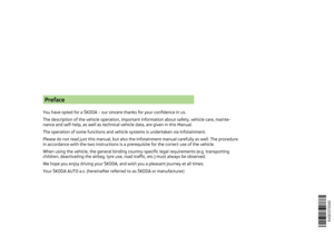 3
3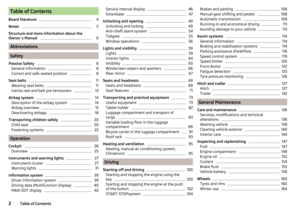 4
4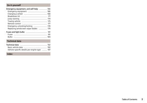 5
5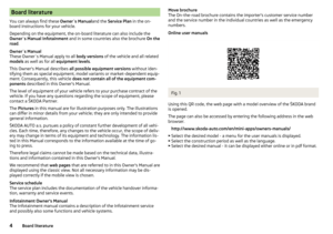 6
6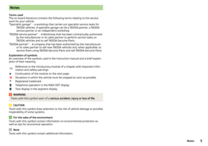 7
7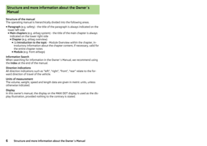 8
8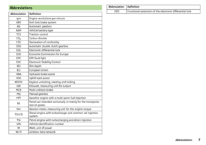 9
9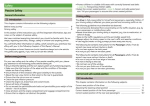 10
10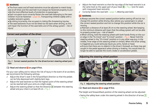 11
11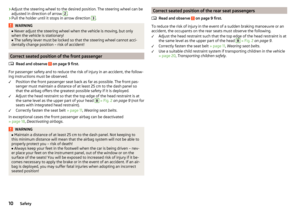 12
12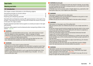 13
13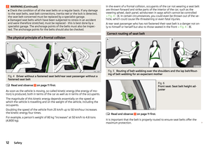 14
14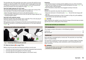 15
15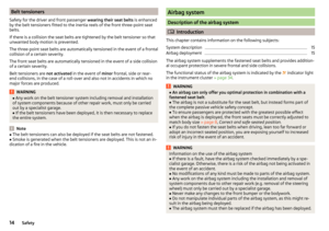 16
16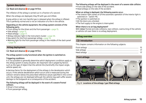 17
17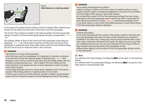 18
18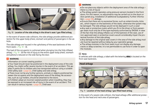 19
19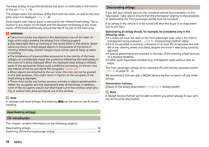 20
20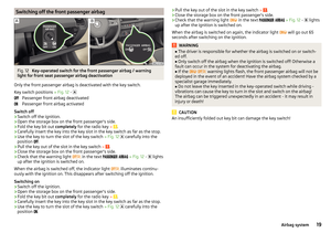 21
21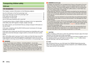 22
22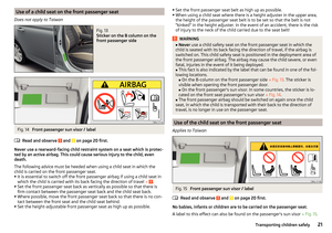 23
23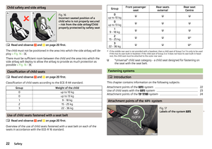 24
24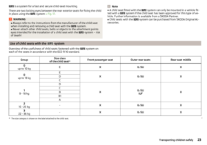 25
25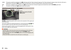 26
26 27
27 28
28 29
29 30
30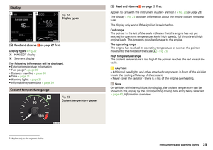 31
31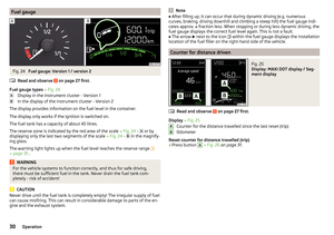 32
32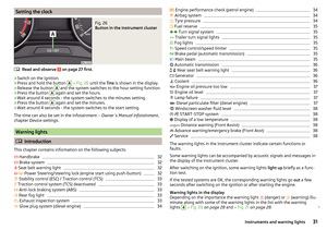 33
33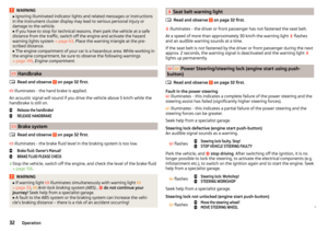 34
34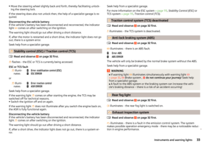 35
35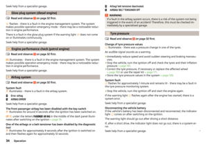 36
36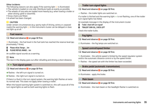 37
37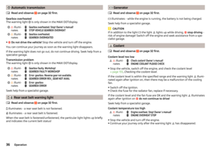 38
38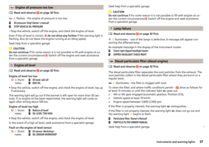 39
39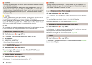 40
40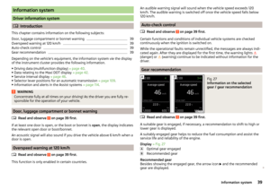 41
41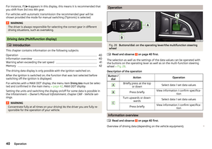 42
42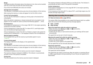 43
43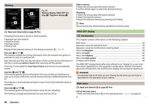 44
44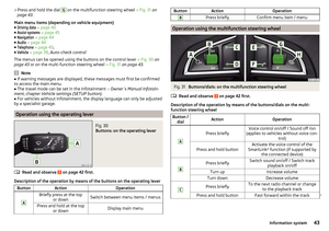 45
45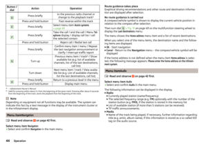 46
46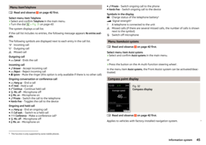 47
47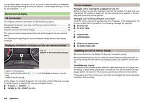 48
48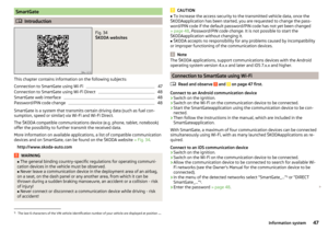 49
49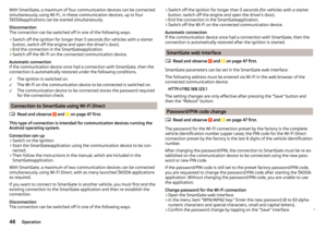 50
50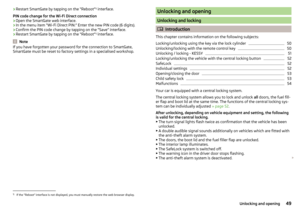 51
51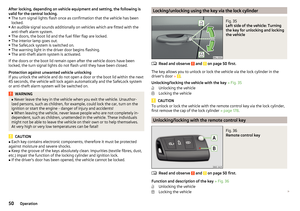 52
52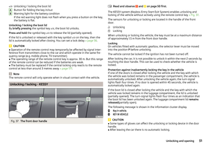 53
53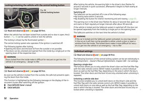 54
54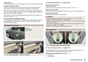 55
55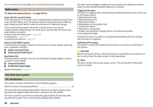 56
56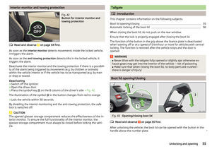 57
57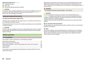 58
58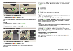 59
59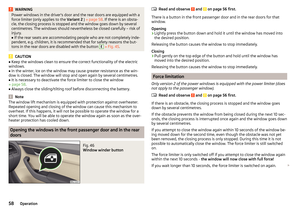 60
60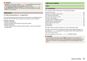 61
61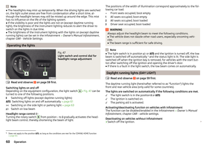 62
62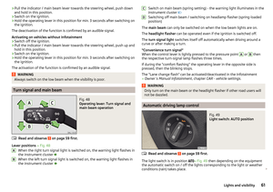 63
63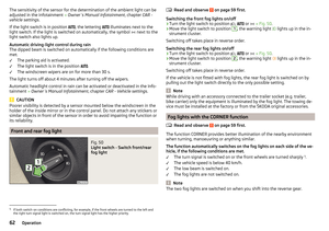 64
64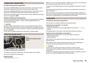 65
65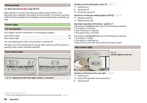 66
66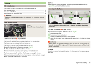 67
67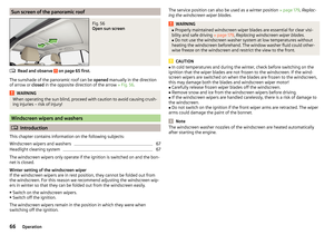 68
68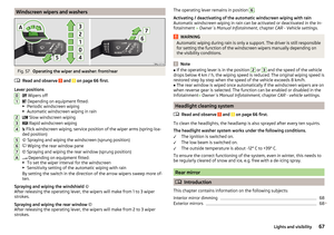 69
69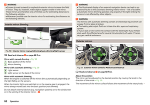 70
70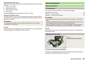 71
71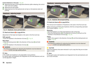 72
72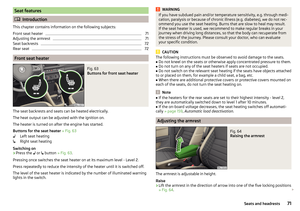 73
73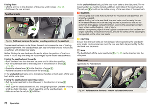 74
74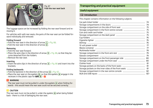 75
75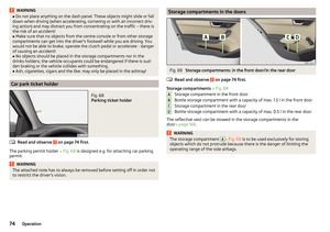 76
76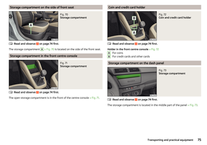 77
77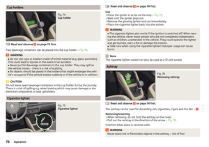 78
78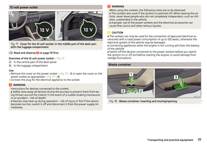 79
79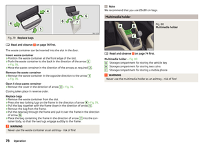 80
80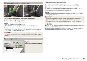 81
81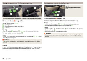 82
82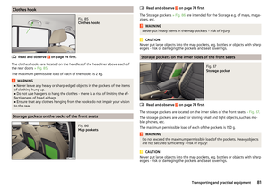 83
83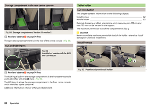 84
84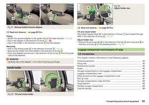 85
85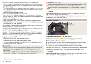 86
86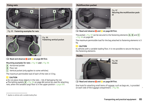 87
87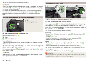 88
88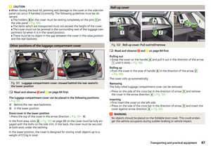 89
89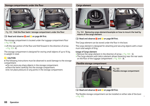 90
90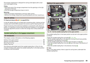 91
91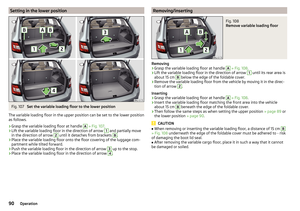 92
92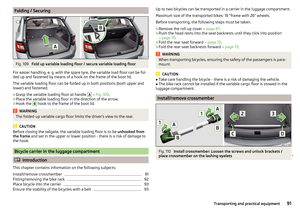 93
93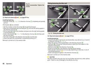 94
94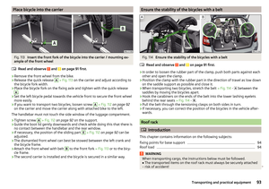 95
95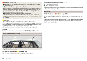 96
96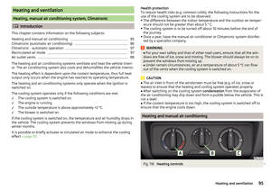 97
97 98
98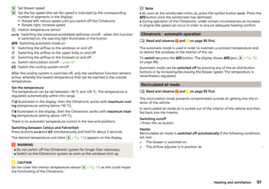 99
99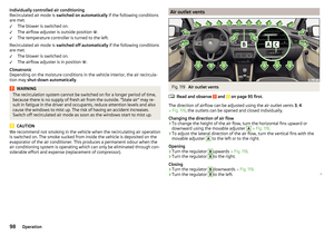 100
100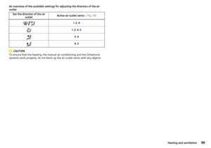 101
101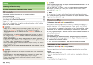 102
102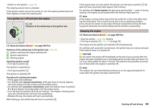 103
103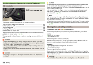 104
104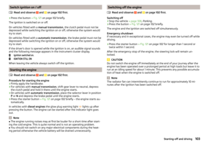 105
105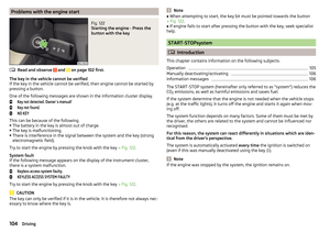 106
106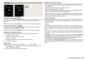 107
107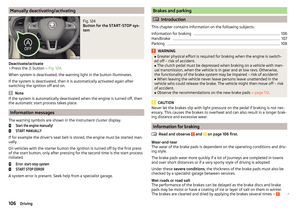 108
108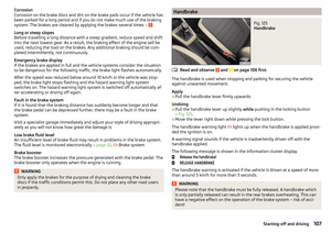 109
109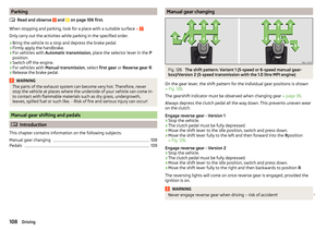 110
110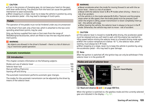 111
111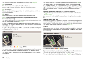 112
112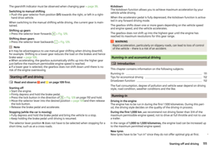 113
113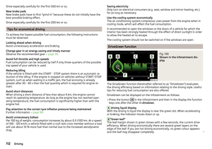 114
114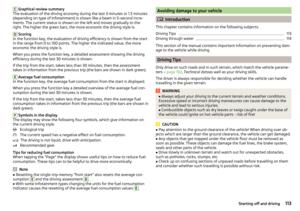 115
115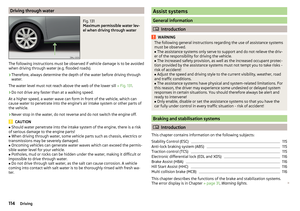 116
116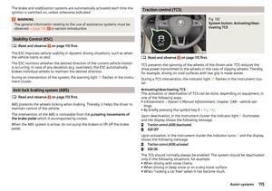 117
117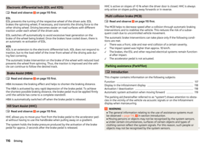 118
118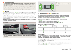 119
119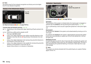 120
120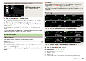 121
121 122
122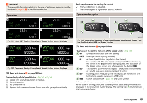 123
123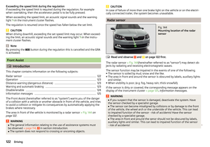 124
124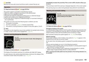 125
125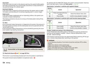 126
126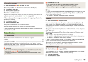 127
127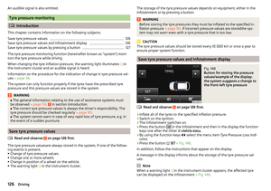 128
128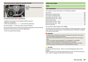 129
129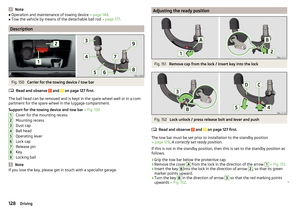 130
130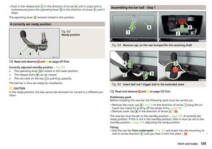 131
131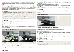 132
132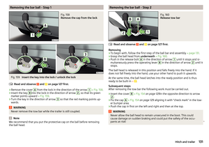 133
133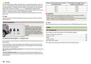 134
134 135
135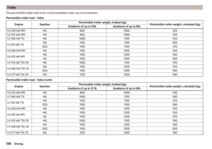 136
136 137
137 138
138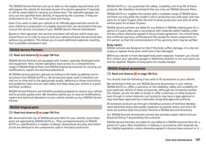 139
139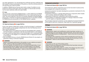 140
140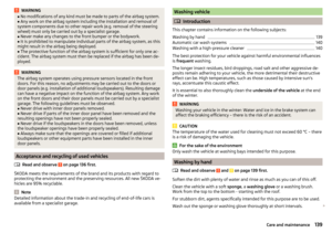 141
141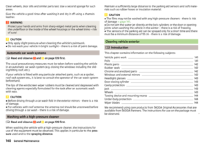 142
142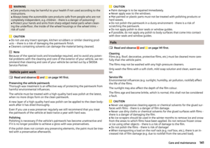 143
143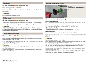 144
144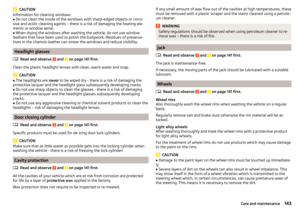 145
145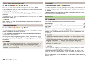 146
146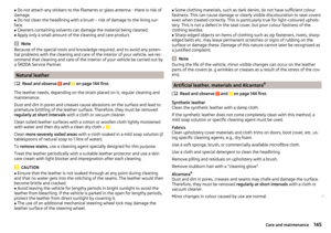 147
147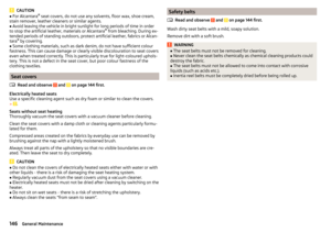 148
148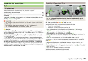 149
149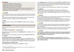 150
150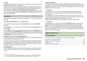 151
151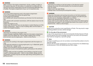 152
152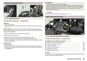 153
153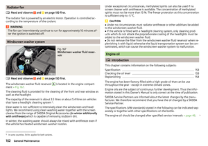 154
154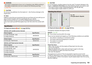 155
155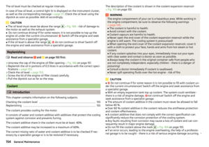 156
156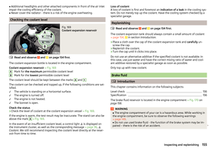 157
157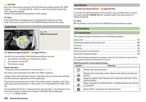 158
158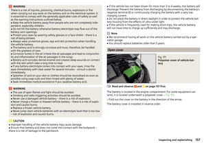 159
159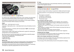 160
160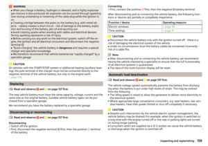 161
161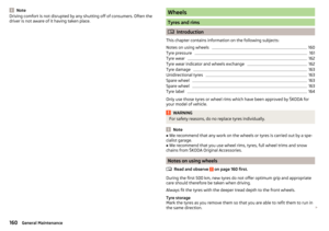 162
162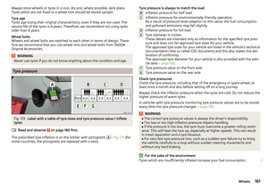 163
163 164
164 165
165 166
166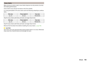 167
167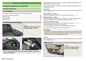 168
168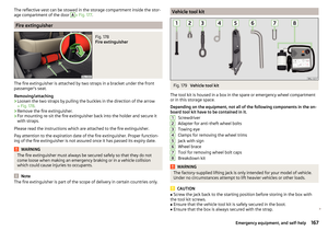 169
169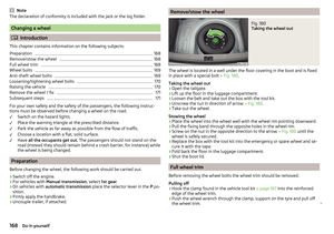 170
170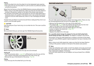 171
171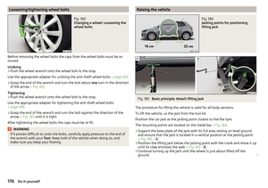 172
172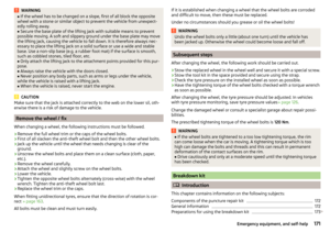 173
173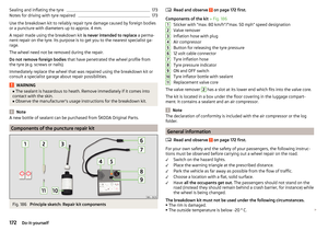 174
174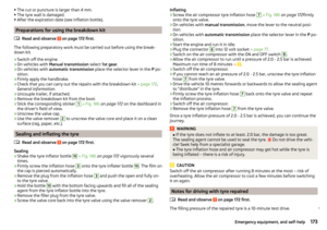 175
175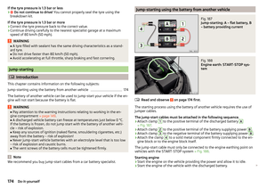 176
176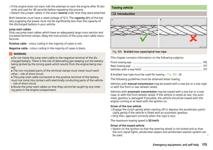 177
177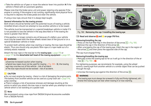 178
178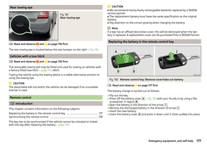 179
179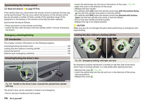 180
180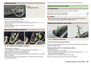 181
181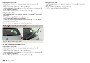 182
182 183
183 184
184 185
185 186
186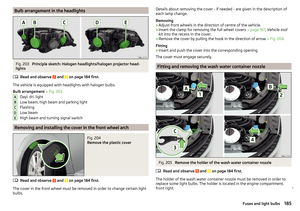 187
187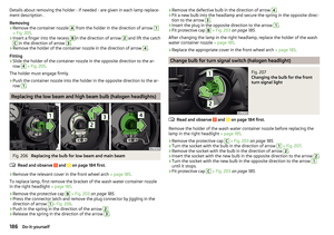 188
188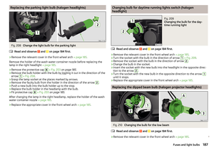 189
189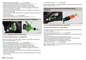 190
190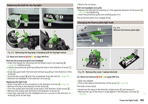 191
191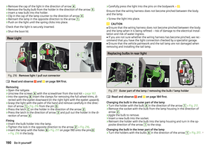 192
192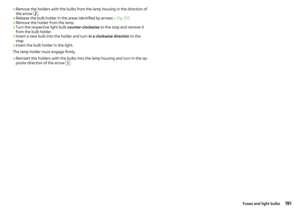 193
193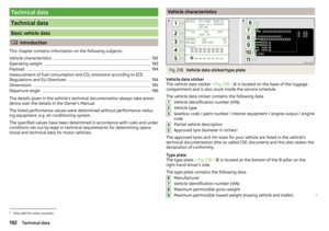 194
194 195
195 196
196 197
197 198
198 199
199 200
200 201
201 202
202 203
203 204
204 205
205 206
206 207
207 208
208 209
209 210
210 211
211 212
212 213
213 214
214 215
215 216
216 217
217 218
218 219
219