Page 177 of 220

›If the engine does not start, halt the attempt to start the engine after 10 sec-
onds and wait for 30 seconds before repeating the process.›
Detach the jumper cables in the exact reverse order that they were attached.
Both batteries must have a rated voltage of 12 V. The capacity (Ah) of the bat-
tery supplying the power must not be significantly less than the capacity of
the discharged battery in your vehicle.
Jump-start cables
Only use jump-start cables which have an adequately large cross-section and
insulated terminal clamps. Obey the instructions of the jump start cable manu-
facturer.
Positive cable - colour coding in the majority of cases is red.
Negative cable - colour coding in the majority of cases is black.
WARNING■
Do not clamp the jump-start cable to the negative terminal of the dis-
charged battery. There is the risk of detonating gas seeping out the battery being ignited by the strong spark which results from the engine being star-
ted.■
The non-insulated parts of the terminal clamps must never touch each
other – risk of short circuit.
■
The jump-start cable connected to the positive terminal of the battery
must not come into contact with electrically conducting parts of the vehicle
– risk of short circuit.
■
Route the jump-start cables so that they cannot be caught by any rotat-
ing parts in the engine compartment.
Towing vehicle
Introduction
Fig. 189
Braided tow ropes/spiral tow rope
This chapter contains information on the following subjects:
Front towing eye
176
Rear towing eye
177
Vehicles with a tow hitch
177
A braided tow rope must be used for towing » Fig. 189 -
.
The following guidelines must be observed when towing.
Vehicles with manual transmission may be towed with a tow bar or a tow rope
or with the front or rear wheels raised.
Vehicles with automatic transmission may be towed with a tow bar or a tow
rope, or with the front wheels raised. If the vehicle is raised at rear, the auto-
matic gearbox is damaged! If possible, the vehicle should be towed with the
engine running or at least with the ignition on.
Driver of the tow vehicle
›
Engage the clutch gently when starting off or depress the accelerator partic-
ularly gently if the vehicle is fitted with an automatic gearbox.
›
Only then, approach correctly when the rope is taut.
The maximum towing speed is 50 km/h.
Driver of the towed vehicle
›
Switch on the ignition so that the steering wheel is not locked and so that
the turn signal lights, windscreen wipers and windscreen washer system can
be used.
175Emergency equipment, and self-help
Page 178 of 220

›Take the vehicle out of gear or move the selector lever into position
N if the
vehicle is fitted with an automatic gearbox.
Please note that the brake servo unit and power steering only operate if the
engine is running. If the engine is not running, significantly more physical force
is required to depress the brake pedal and steer the vehicle.
If using a tow rope, ensure that it is always kept taught.
General information for the towing process
Both drivers should be familiar with the potential issues of towing a vehicle.
Unskilled drivers should not attempt to tow another vehicle or to be towed.
The vehicle must be transported on a special breakdown vehicle or trailer if it
is not possible to tow the vehicle in the way described or if the towing dis-
tance is greater than 50 km.
If the gearbox no longer contains any oil because of a defect, your vehicle
must only be towed with the drive wheels raised clear of the ground or on a
special breakdown vehicle or trailer.
To protect both vehicles when tow-starting or towing, the tow rope should be
elastic. Thus one should only use plastic fibre rope or a rope made out of a
similarly elastic material.
Attach the tow rope or the tow bar to the towing eyes » page 176 or
» page 177 to the detachable ball head of the towing equipment » page 127 .WARNING■
Exercise increased caution when towing.■Spiral tow ropes must not be used for towing » Fig. 189 - , the towing
eye may unscrew out of the vehicle - risk of accident.■
The tow rope should not be twisted - risk of accident.
CAUTION
■ Do not start engine by towing - there is a risk of damaging the engine parts.
The battery from another vehicle can be used as a jump-start aid » page 174,
Jump-starting .■
There is always a risk of excessive stresses and damage resulting at the
points to which you attach the tow rope or tow bar when you attempt to tow a
vehicle which is not standing on a paved road.
Note
We recommend using a tow rope from ŠKODA Original Accessories available
from a ŠKODA Partner.Front towing eyeFig. 190
Removing the cap / installing the towing eye
Read and observe
and on page 176 first.
Removing/installing the cap
›
Press on the fuel filler flap in the direction of the arrow
1
» Fig. 190 .
›
Remove the cap in the direction of the arrow
2
.
›
After unscrewing the cap of the towing eye, insert the cap in the region of
the arrow
1
and then press the opposite side of the cap.
The cap must engage firmly.
Removing/installing the towing eye
›
Manually screw the towing eye as far as it will go in the direction of the ar-
row
3
» Fig. 190 » .
For tightening purposes, we recommend, for example, using the wheel
wrench, towing eye from another vehicle or a similar object that can be pushed through the eye.
›
Unscrew the towing eye against the direction of the arrow
3
.
WARNINGThe towing eye must always be screwed in fully and firmly tightened, oth-
erwise the towing eye can tear when towing in or tow-starting.176Do-it-yourself
Page 179 of 220

Rear towing eyeFig. 191
Rear towing eye
Read and observe and on page 176 first.
The rear towing eye is located below the rear bumper on the right » Fig. 191.
Vehicles with a tow hitch
Read and observe
and on page 176 first.
The removable towing ball may be fitted and used for towing on vehicles with
a factory fitted tow hitch » page 127, Hitch .
Towing the vehicle using the towing device is a viable alternative solution to
using the towing eye.
CAUTION
The detachable ball rod and/or the vehicle can be damaged if an unsuitable
tow bar is used.
Remote control
Introduction
This chapter contains information on the following subjects:
Replacing the battery in the remote control key
177
Synchronising the remote control
178
The key has to be synchronised if the vehicle cannot be unlocked or locked
with the key after replacing the battery » page 178.
CAUTION■
We recommend having faulty rechargeable batteries replaced by a ŠKODA
service partner.■
The replacement battery must have the same specification as the original
battery.
■
Pay attention to the correct polarity when changing the battery.
Note
If a key has an affixed decorative cover, this will be destroyed when the bat-
tery is replaced. A replacement cover can be purchased from a ŠKODA Partner.
Replacing the battery in the remote control key
Fig. 192
Remote control key: Remove cover/take out battery
Read and observe
on page 177 first.
The battery change is carried out as follows.
›
Flip out the key.
›
Press off the battery cover
A
» Fig. 192 with your thumb or by using a flat
screwdriver in region
B
.
›
Open the battery in the direction of the arrow
1
.
›
Remove the discharged battery in the direction of arrow
2.›
Insert the new battery.
›
Insert the battery cover
A
and press it down until it clicks audibly into place.
177Emergency equipment, and self-help
Page 180 of 220

Synchronising the remote controlRead and observe
on page 177 first.
If the vehicle does not unlock when the remote control is pressed, the key maynot be synchronised. This can occur when the buttons on the remote control
key are actuated a number of times outside of the operative range of the
equipment or the battery in the remote control key has been replaced.
Synchronise the key as follows.
›
Press any button on the remote control key.
›
Unlock the door with the key in the lock cylinder within 1 minute of pressing the button.
Emergency unlocking/locking
Introduction
This chapter contains information on the following subjects:
Unlocking/locking the driver's door
178
Locking the door without a locking cylinder
178
Unlock the boot lid
179
Selector lever-emergency unlocking
179
Unlocking/locking the driver's door
Fig. 193
Handle on the driver's door: covered lock cylinder/lock cylinder
with key
The driver's door can be unlocked or locked in an emergency.
›
Pull on the door handle and hold it pulled.
› Insert the vehicle key into the slot on the bottom of the cover
» Fig. 193.›Open the cover in the direction of the arrow.›
Release the door handle.
›
For vehicles with LHD insert the remote control key with the buttons facing
up into the lock cylinder and unlock or lock the vehicle.
›
For vehicles with RHD insert the remote control key directed with buttons
down into the lock cylinder and unlock or lock the vehicle.
›
Pull on the door handle and hold it pulled.
›
Replace the cap in its original position.
CAUTION
Make sure you do not damage the paint when performing an emergency lock-
ing/unlocking.
Locking the door without a locking cylinder
Fig. 194
Emergency locking: Left/right rear door
An emergency locking mechanism is located on the face side of the doors
which have no locking cylinder. It is only visible after opening the door.
›
Remove the cover
A
» Fig. 194 .
›
Insert the vehicle key into the slot and turn in the direction of the arrow
(sprung position).
›
Replace the cover
A
.
178Do-it-yourself
Page 181 of 220

Unlock the boot lidFig. 195
Unlocking the boot lid
The boot lid can be unlocked manually.
›
Fold the rear seat backrest forward » page 72.
›
Insert a screwdriver or similar tool into the opening in the trim
» Fig. 195 as
far as the stop.
›
Unlock the lid by moving it in the direction of the arrow.
›
Open the tailgate.
Selector lever-emergency unlocking
Fig. 196
Selector lever-emergency unlocking
›
Firmly apply the handbrake.
›
Insert a flathead screwdriver into the gap in the arrow range
1
» Fig. 196
and carefully lift the cover in arrow direction
2
.
›
Likewise lift the cover with your hand as well.
›
With one finger, push the yellow plastic element in the direction of arrow
3
down to the stop.
›
At the same time, press the locking button in the selector lever and move
the selector lever to N.
The selector lever will be locked once more if it is moved again to P.
Replacing windscreen wiper blades
Introduction
This chapter contains information on the following subjects:
Replacing the windscreen wiper blades
179
Replacing the rear window wiper blade
180WARNINGReplace the windscreen wiper blades once or twice a year for safety rea-
sons. These can be purchased from a ŠKODA Partner.
Replacing the windscreen wiper blades
Fig. 197
Windscreen wiper blade
Read and observe
on page 179 first.
Adjust the windscreen wiper arms to the service position before replacing the windscreen wiper blades.
Adjusting service position for changing wiper blades
›
Close the bonnet.
›
Switch the ignition on and off again.
›
Push the windscreen wiper lever to position
4
within 10 seconds » page 67,
Windscreen wipers and washers .
›
Hold the lever in this position for about 2 seconds.
Move the windscreen wiper arms into the service position.
179Emergency equipment, and self-help
Page 182 of 220

Removing the wiper blade›Lift the wiper arm from the window in the direction of the arrow 1
» Fig. 197.
›
Tilt the wiper blade to the stop in the same direction.
›
Hold the upper part of the wiper arm and press the securing mechanism
A
in the direction of arrow
2
.
›
Remove the wiper blade in the direction of the arrow
3
.
Fitting the wiper blade
›
Push the wiper blade in the opposite direction of the arrow
3
until it locks
intoo place.
›
Check that the wiper blade is correctly attached.
›
Fold the wiper arm back to the windscreen.
›
Turn on the ignition and press the lever into position
4
» page 67 , Wind-
screen wipers and washers .
Move the windscreen wiper arms into the home position.
Replacing the rear window wiper blade
Fig. 198
Rear window wiper blade
Read and observe
on page 179 first.
Removing the wiper blade
›
Lift the wiper arm from the window in the direction of the arrow
1
» Fig. 198 .
›
Tilt the wiper blade to the stop in the same direction.
›
Hold the upper part of the wiper arm and press the securing mechanism
A
in the direction of arrow
2
.
›
Remove the wiper blade in the direction of the arrow
3
.
Fitting the wiper blade›Push the wiper blade in the opposite direction of the arrow 3 until it locks
into place.›
Check that the wiper blade is correctly attached.
›
Fold the wiper arm back to the windscreen.
180Do-it-yourself
Page 183 of 220

Fuses and light bulbs
Fuses
Introduction
This chapter contains information on the following subjects:
Fuses in the dash panel
181
Assignment of the fuses in the dash panel
182
Fuses in the engine compartment
183
Fuse assignment in the engine compartment
183
Individual electrical circuits are protected by fuses.
Switch off the ignition and the corresponding power consuming device before
replacing a fuse.
Find out which fuse belongs to the component that is not operating
» page 181 , Fuses in the dash panel or » page 183 , Fuses in the engine com-
partment .
Fuse colourMaximum amperagepurple3light brown5dark brown7.5red10blue15yellow/blue20white25green/pink30green40red50WARNINGAlways read and observe the warnings before completing any work in the
engine compartment » page 149.CAUTION■
“Never repair” fuses or replace them with a fuse of a higher amperage – risk
of fire. This may also cause damage at another part of the electrical system.■
If a newly inserted fuse blows again after a short time, have the electrical
system checked as quickly as possible by a specialist garage.
■
A blown fuse is recognisable by the molten metal strip. Replace the faulty
fuse with a new one of the same amperage.
Note
■
We recommend that you always carry replacement fuses in the vehicle. A box
of replacement fuses and bulbs can be purchased from ŠKODA Original Acces-
sories.■
One fuse may cover several consumers.
■
A single consumer may use several fuses.
Fuses in the dash panel
Fig. 199
Remove the cover
Read and observe and on page 181 first.
The fuses are located on the bottom of the dash panel behind a cover.
Replacing fuses
›
Remove the cover of the fuse box » Fig. 199 in the direction of the arrow.
›
Remove the plastic clip from the holder in the fuse box cover.
›
Place the clamp on the respective fuse and pull this fuse out.
›
Insert a new fuse.
›
Replace the clamp in the original position.
›
Insert the top edge of the cover into the dash panel first.
›
Push the lower edge of the cover in the region
A
.
181Fuses and light bulbs
Page 184 of 220

Assignment of the fuses in the dash panelFig. 200
Schematic representation of the fuse box for vehicles with left-
hand steering/right-hand steering
Read and observe
and on page 181 first.
No.Power consumer1Left parking light, parking light, high-mounted brake light2Central locking system3Relay for ignition4Right-hand light, rear fog light, license plate light5Power windows - driver6Central control unit, interior lighting7Horn8Towing hitch - left light
9
Operating lever beneath the steering wheel, engine control unit (on-
ly without KESSY), automatic gearbox (only without KESSY), selector
lever of the automatic transmission (only without KESSY), ESC (only
without KESSY), towing equipment (only without KESSY), power
steering (only without KESSY)10Power windows - rear left11Headlight cleaning system12Radio display1312 volt socket in luggage compartment14Operating lever under the steering wheel, light switch, ignition key
removal lock (automatic transmission), diagnostic connector, head-
light flasher, SmartGate, rain sensor, light sensorNo.Power consumer15Air conditioning, selector lever for the automatic transmission16Instrument cluster17Alarm system, horn18Not assigned19Not assigned20Not assigned21Not assigned22Front- and rear windscreen wiper system23Not assigned24Blower fan for the air conditioning system, heating, air conditioning,
heating25Not assigned26Switch for front seat heating27Rear window wiper28Not assigned29airbag30Power windows, light switches, reversing light switch, exterior mir-
rors, feed for the central toolbar, feed for the side toolbar, rear view
mirror31Fuel pump, radiator fan, cruise control, coil of the relay for the front
and rear windscreen wipers32Diagnostic connector, headlamp levelling, air conditioning, park as-
sist33Coil on starter relay, clutch pedal switch34Heated windscreen washer jets35Not assigned36Heated front seats37Radar38Not assigned39Electrical auxiliary heating system40Not assigned41Rear window heater42Power windows - front passenger 182Do-it-yourself
 1
1 2
2 3
3 4
4 5
5 6
6 7
7 8
8 9
9 10
10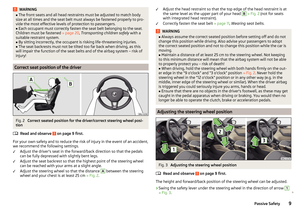 11
11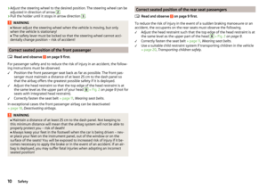 12
12 13
13 14
14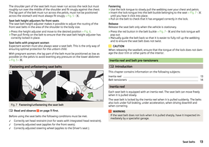 15
15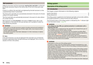 16
16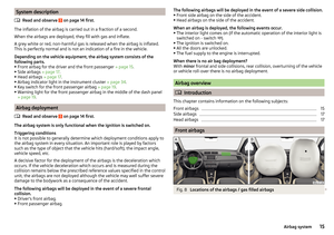 17
17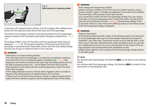 18
18 19
19 20
20 21
21 22
22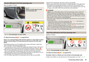 23
23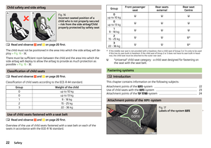 24
24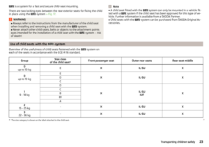 25
25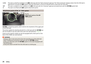 26
26 27
27 28
28 29
29 30
30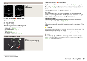 31
31 32
32 33
33 34
34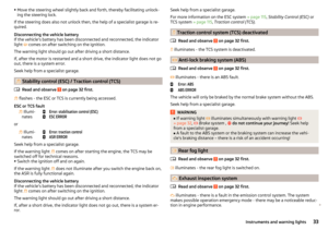 35
35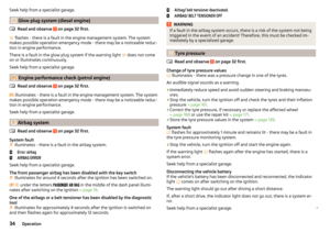 36
36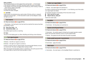 37
37 38
38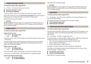 39
39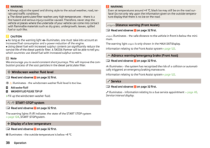 40
40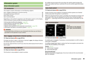 41
41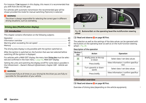 42
42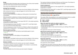 43
43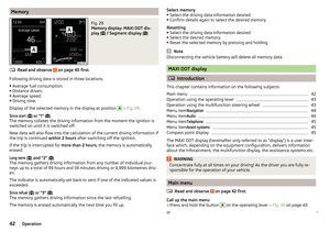 44
44 45
45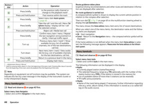 46
46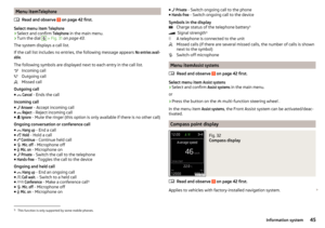 47
47 48
48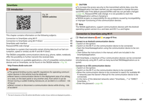 49
49 50
50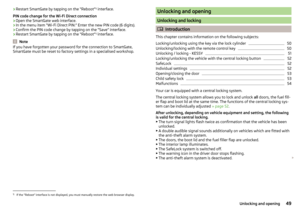 51
51 52
52 53
53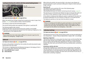 54
54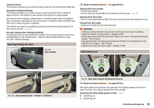 55
55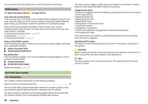 56
56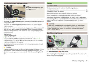 57
57 58
58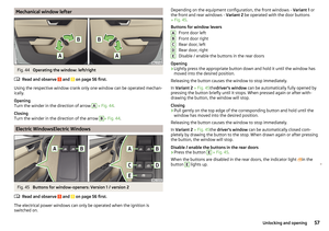 59
59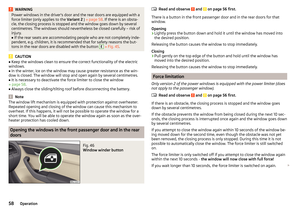 60
60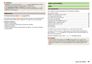 61
61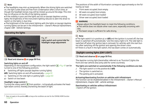 62
62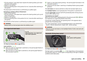 63
63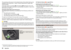 64
64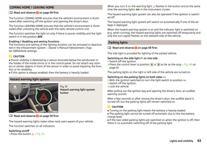 65
65 66
66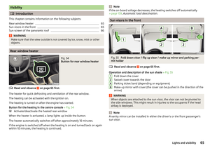 67
67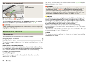 68
68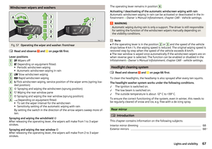 69
69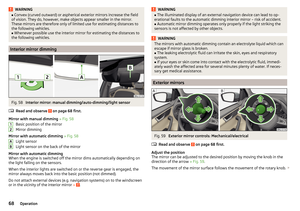 70
70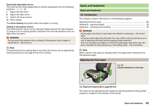 71
71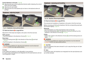 72
72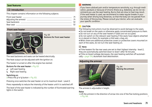 73
73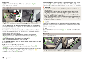 74
74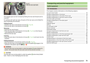 75
75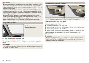 76
76 77
77 78
78 79
79 80
80 81
81 82
82 83
83 84
84 85
85 86
86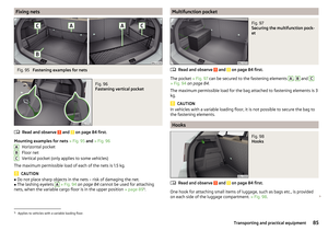 87
87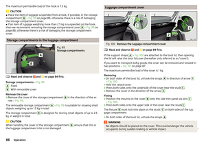 88
88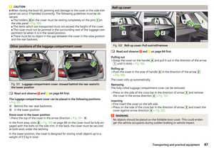 89
89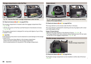 90
90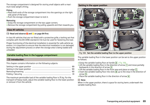 91
91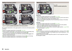 92
92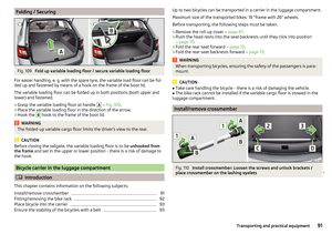 93
93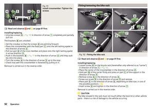 94
94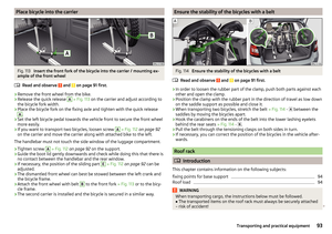 95
95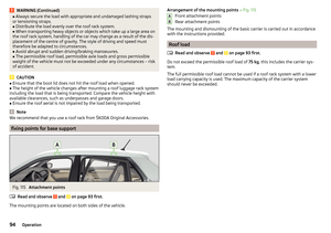 96
96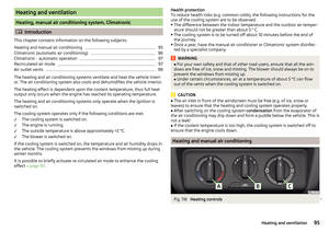 97
97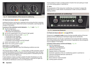 98
98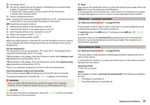 99
99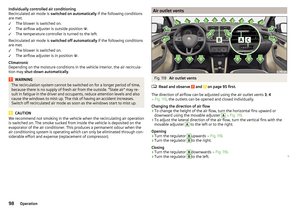 100
100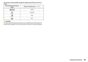 101
101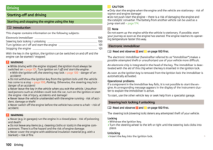 102
102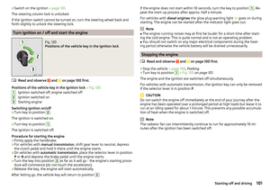 103
103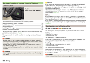 104
104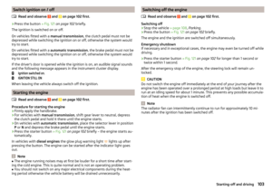 105
105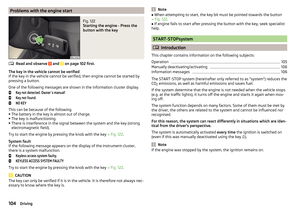 106
106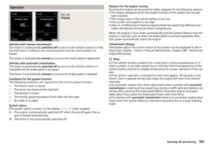 107
107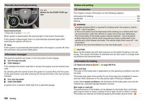 108
108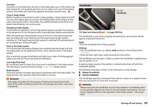 109
109 110
110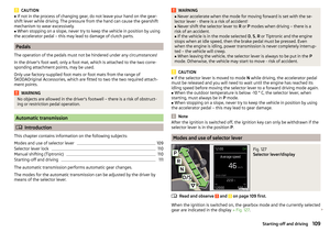 111
111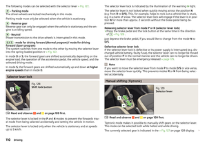 112
112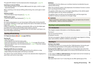 113
113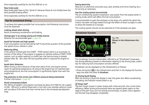 114
114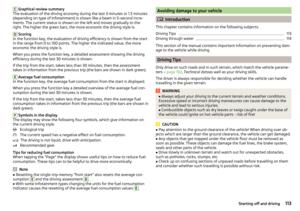 115
115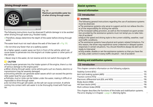 116
116 117
117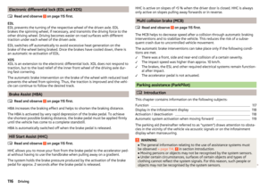 118
118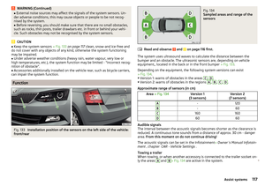 119
119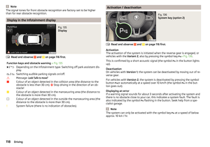 120
120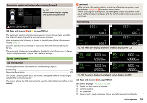 121
121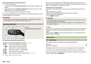 122
122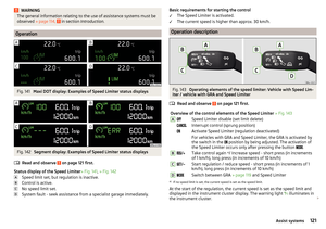 123
123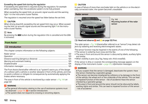 124
124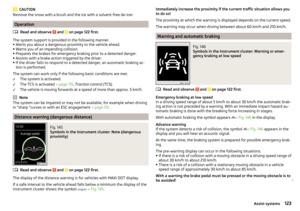 125
125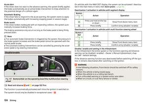 126
126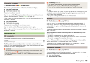 127
127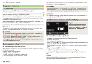 128
128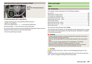 129
129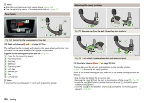 130
130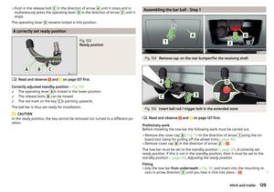 131
131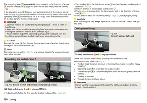 132
132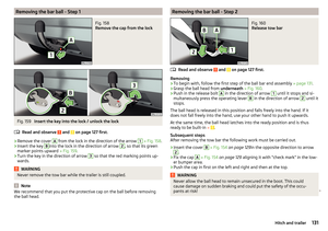 133
133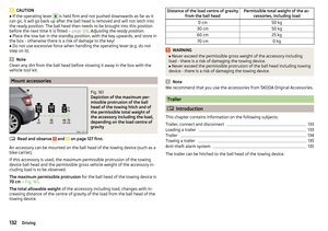 134
134 135
135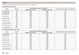 136
136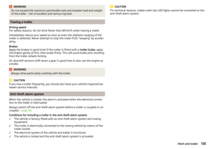 137
137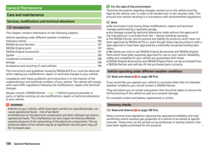 138
138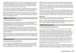 139
139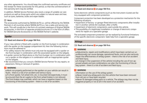 140
140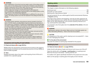 141
141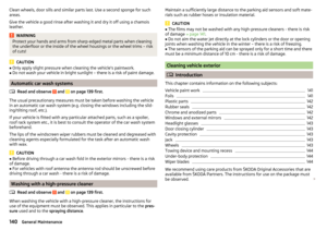 142
142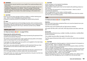 143
143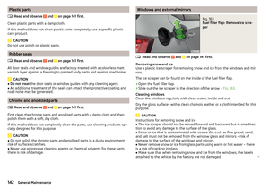 144
144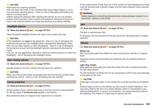 145
145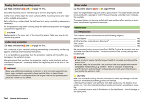 146
146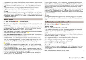 147
147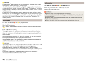 148
148 149
149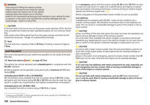 150
150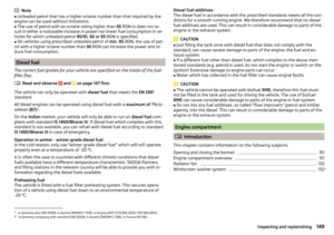 151
151 152
152 153
153 154
154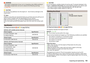 155
155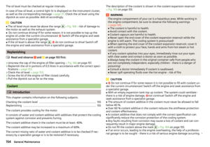 156
156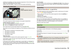 157
157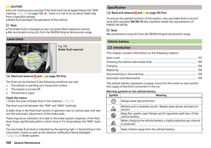 158
158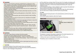 159
159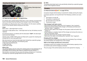 160
160 161
161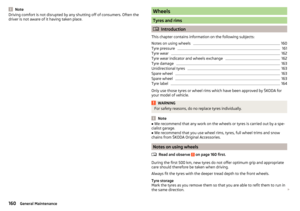 162
162 163
163 164
164 165
165 166
166 167
167 168
168 169
169 170
170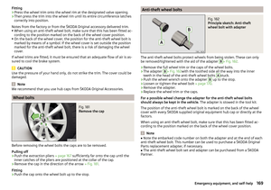 171
171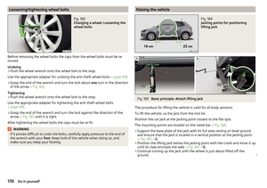 172
172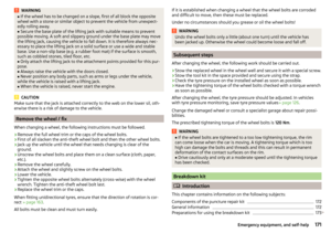 173
173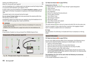 174
174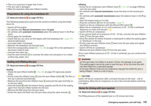 175
175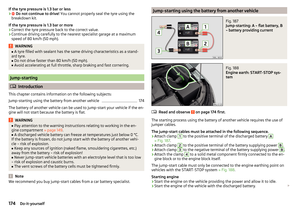 176
176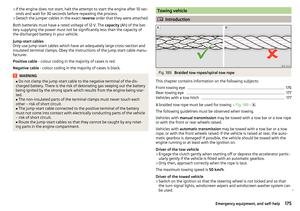 177
177 178
178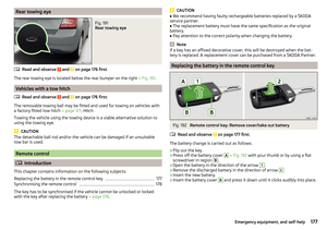 179
179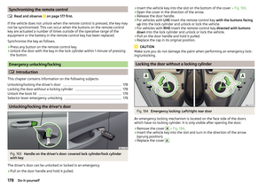 180
180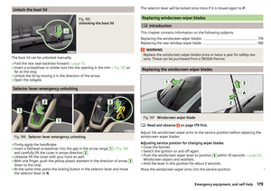 181
181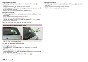 182
182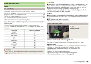 183
183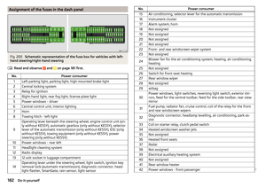 184
184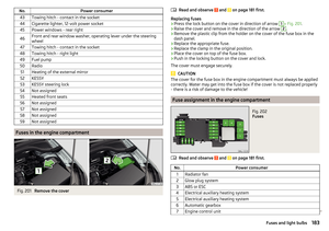 185
185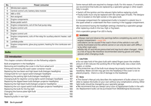 186
186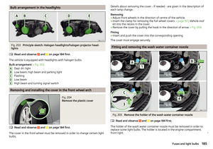 187
187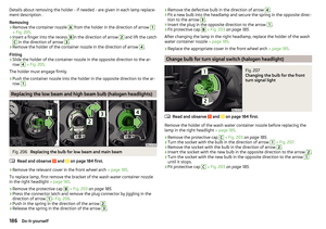 188
188 189
189 190
190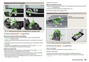 191
191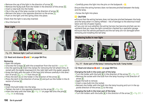 192
192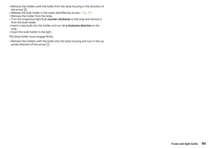 193
193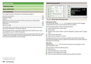 194
194 195
195 196
196 197
197 198
198 199
199 200
200 201
201 202
202 203
203 204
204 205
205 206
206 207
207 208
208 209
209 210
210 211
211 212
212 213
213 214
214 215
215 216
216 217
217 218
218 219
219