Page 121 of 220

Automatic system activation when moving forwardFig. 137
Infotainment display: Display
with automatic activation
Read and observe and on page 116 first.
The automatic system activation occurs when moving forward at a speed be-
low 10 km / h when the vehicle approaches an obstacle.
After activation, the following is shown in the left pane of the Infotainment
display » Fig. 137 .
Acoustic signals are sounded as of a distance from the obstacle of around
50 cm.
The automatic display can be enabled or disabled in the Infotainment » Owner
´s Manual Infotainment , chapter CAR - vehicle settings .
Speed control system
Introduction
This chapter contains information on the following subjects:
Functioning
119
Operating Description
120
The Cruise Control System (CCS) maintains a set speed without you having to
actuate the accelerator pedal.
The status where the CCS maintains the speed is referred to hereinafter as the
control .
WARNING■
The general information relating to the use of assistance systems must
be observed » page 114, in section Introduction .■
After pressing the clutch pedal, no interrupted control occurs! For exam-
ple, if a different gear is engaged and the clutch pedal is released, control is
continued.
Functioning
Fig. 138
Maxi DOT display: Examples of status displays the CCS
Fig. 139
Segment display: Examples of status displays the CCS
Read and observe
on page 119 first.
CCS status displays » Fig. 138 , » Fig. 139
Speed set, but control is inactive.
Control is active.
No speed set.
System fault - seek assistance from a specialist garage immediately.
119Assist systems
Page 122 of 220

Basic requirements for starting the controlThe CCS is activated.
On vehicles with a manual transmission , the second gear or higher is en-
gaged.
On vehicles with an automatic transmission , the selector lever is in the
D/S position or in the Tiptronic position.
The current speed is higher than approx. 20 km/h.
This is only possible within the range which is permitted by the power output
and braking power of the engine.WARNINGIf the engine power and engine braking effect is insufficient to maintain
the set speed, vehicle operation must be taken over!
Operating Description
Fig. 140
Cruise control system controls
Read and observe on page 119 first.
Overview of the control elements of the CCS » Fig. 140ADeactivate CCS (delete set speed) Interrupt control (sprung position) Activate CCS (control deactivated)BTake control again a)
/ Increase speedCStart control / reduce speedDSwitch between GRA and Speed Limiter » page 120a)
If no speed is set the current speed is adopted.
At the start of the regulation the GRA regulates the vehicle to the current
speed, and this speed is shown on the instrument cluster display. The warning
light
illuminates in the instrument cluster.
Automatic control interruption
Automatic control interruption occurs if any of the following conditions are
met.
▶ The brake pedal is operated.
▶ When one of the brake assist systems (e.g. ESC) intervenes.
▶ Through an airbag deployment.
▶ The key
is actuated.WARNING■
Always deactivate the cruise control system after use to prevent the sys-
tem being enabled unintentionally.■
Control may only be resumed if the set speed is not too high for the cur-
rent traffic conditions.
Note
■ During control, speed can be increased by pressing the accelerator pedal. Re-
leasing the accelerator pedal will cause the speed to drop again to the set
speed.■
By pressing the
button during the regulation this is cancelled and the
Speed Limiter is activated.
Speed limiter
Introduction
This chapter contains information on the following subjects:
Operation
121
Operation description
121
The Speed Limiter limits the maximum driving speed to the set speed limit.
This limit can only be exceeded by depressing the accelerator pedal fully.
The condition in which the Speed Limiter monitors a potential set speed limit
excess is referred to as Regulation.
120Driving
Page 123 of 220

WARNINGThe general information relating to the use of assistance systems must be
observed » page 114, in section Introduction .
Operation
Fig. 141
Maxi DOT display: Examples of Speed Limiter status displays
Fig. 142
Segment display: Examples of Speed Limiter status displays
Read and observe
on page 121 first.
Status display of the Speed Limiter » Fig. 141, » Fig. 142
Speed limit set, but regulation is inactive.
Control is active.
No speed limit set.
System fault - seek assistance from a specialist garage immediately.
Basic requirements for starting the control The Speed Limiter is activated.
The current speed is higher than approx. 30 km/h.
Operation description
Fig. 143
Operating elements of the speed limiter: Vehicle with Speed Lim-
iter / vehicle with GRA and Speed Limiter
Read and observe
on page 121 first.
Overview of the control elements of the Speed Limiter » Fig. 143ASpeed Limiter disable (set limit delete) Interrupt control (sprung position) Activate Speed Limiter (regulation deactivated) For vehicles with GRA and Speed Limiter, the GRA is activated by
the switch in the
position by being adjusted. The activation of
the Speed Limiter occurs only after pressing the button
.BTake control again a)
/ Increase speed - short press (in increments
of 1 km/h), long press (in increments of 10 km/h)CStart regulation / reduce speed - short press (in increments of 1
km/h), long press (in increments of 10 km/h)DSwitch between GRA » page 119 and Speed Limitera)
If no speed limit is set, the current speed is set as the speed limit.
At the start of the regulation, the current speed is set as the speed limit and
displayed in the instrument cluster display. The warning light illuminates in
the instrument cluster.
121Assist systems
Page 124 of 220

Exceeding the speed limit during the regulation
If exceeding the speed limit is required during the regulation, for example
when overtaking, then the accelerator pedal is to be fully pressed.
When exceeding the speed limit, an acoustic signal sounds and the warning
light
in the instrument cluster flashes.
The regulation is resumed once the speed has fallen below the set limit.
CAUTION
When driving downhill, exceeding the set speed limit may occur. When exceed-
ing the limit, an acoustic signal sounds and the warning light in the instru-
ment cluster flashes.
Note
By pressing the button during the regulation this is cancelled and the GRA
is activated.
Front Assist
Introduction
This chapter contains information on the following subjects:
Radar sensor
122
Operation
123
Distance warning (dangerous distance)
123
Warning and automatic braking
123
Disable/enable
124
Information messages
125
The Front Assist (hereinafter referred to as "system") warns you of the danger
of a collision with a vehicle or another obstacle in front of the vehicle, and tries
to avoid a collision or mitigate its consequences by automatically applying the
brakes where necessary.
The area in front of the vehicle is monitored by a radar sensor » Fig. 144 on
page 122 .
WARNING■
The general information relating to the use of assistance systems must
be observed » page 114, in section Introduction .■
The system does not respond to crossing or oncoming objects.
CAUTIONIn case of failure of more than one brake light on the vehicle or on the electri-
cally connected trailer, the system becomes unavailable.
Radar sensor
Fig. 144
Mounting location of the radar
sensor
Read and observe and on page 122 first.
The radar sensor » Fig. 144(hereinafter referred to as "sensor") may detect ob-
jects by radiating and receiving electromagnetic waves.
The sensor function may be impaired in the events of one of the following. ▶ The sensor is soiled by mud, snow and the like.
▶ The area in front and around the sensor is obscured by labels, auxiliary lights
and similar.
▶ When visibility is poor, (e.g. fog, heavy rain, thick snowfall).
If the sensor is dirty or covered, the corresponding message appears on the
display of the instrument cluster » page 125, Information messages .
WARNING■
If you suspect that the sensor is damaged, deactivate the system. Have
the sensor checked by a specialist garage.■
The sensor can become misaligned by collisions or by damage to the front
of the vehicle, the wheel arch or the underside of the vehicle. This can lead
to impaired function of the sensor - risk of accidents! Have the sensor
checked by a specialist garage.
■
The area in front and around the senor should not be obscured by labels,
auxiliary lights and similar. This can lead to impaired function of the sensor
- risk of accidents!
122Driving
Page 125 of 220

CAUTIONRemove the snow with a brush and the ice with a solvent-free de-icer.
OperationRead and observe
and on page 122 first.
The system support is provided in the following manner.▶ Alerts you about a dangerous proximity to the vehicle ahead.
▶ Warns you of an impending collision.
▶ Prepares the brakes for emergency braking prior to a detected danger.
▶ Assists with a brake action triggered by the driver.
▶ If the driver fails to respond to a detected danger, an automatic braking ac-
tion is performed.
The system can work only if the following basic conditions are met. The system is activated.
The TCS is activated » page 115, Traction control (TCS) .
The vehicle is moving forwards at a speed of more than approx. 5 km/h.
Note
The system can be impaired or may not be available, for example when driving
in “sharp ”curves or with an ESC engagement » page 115.
Distance warning (dangerous distance)
Fig. 145
Symbols in the instrument cluster: Note (dangerous
proximity)
Read and observe and on page 122 first.
The display of the distance warning is for vehicles with MAXI DOT display.
If a safe interval to the vehicle ahead falls below a minimum the display of the
instrument cluster shows the symbol
» Fig. 145 .
Immediately increase the proximity if the current traffic situation allows you
to do so!
The proximity at which the warning is displayed depends on the current speed.
The warning may occur when driving between about 60 km/h and 210 km/h.
Warning and automatic braking
Fig. 146
Symbols in the instrument cluster: Warning or emer-
gency braking at low speed
Read and observe and on page 122 first.
Emergency braking at low speed
In a driving speed range of about 5 km/h to about 30 km/h the automatic brak-
ing action is not preceded by a warning. With an immediate impact hazard au-
tomatic braking is done with the breaking force increasing in stages.
With automatic braking the symbol appears » Fig. 146
in the display.
Advance warning
If the system detects a risk of collision, the symbol » Fig. 146
appears in the
display and you will hear an acoustic signal.
At the same time, the braking system is prepared for possible emergency brak- ing.
The pre-warning display can occur in the following situations. ▶ If there is a risk of collision with a moving obstacle in a driving speed range of
about 30 km/h to about 210 km/h.
▶ There is a risk of a collision with a stationary moving obstacle in a vehicle
speed range of approximately 30 km/h to about 85 km/h.
With a warning the brake pedal must be pressed or the moving obstacle is to
be avoided!
123Assist systems
Page 126 of 220

Acute alert
If the driver does not react to the advance warning, the system briefly applies
the brake automatically via an active brake intervention to draw attention to
the potential danger of a collision again.
Automatic Braking
If the driver fails to respond to the acute warning, the system starts to apply
the brakes automatically with increasing stopping power in several stages.
Brake assist
If the driver brakes inadequate with an impending collision, the system auto-
matically increases braking force.
The braking assistance only occurs as long as the brake pedal is being firmly
pressed down.
Note
■ If an automatic brake intervention is triggered by the system, the pressure in
the brake system increases and the brake pedal cannot be operated with the
normal pedal stroke.■
The automatic braking interventions can be cancelled by pressing the accel-
erator pedal or by steering intervention.
Disable/enable
Fig. 147
Buttons/dial: on the operating lever/the multifunction steering
wheel
Read and observe
and on page 122 first.
The function is automatically activated each time the ignition is switched on.
The system should only be disabled in exceptional cases »
.
On vehicles with the MAXI DOT display, the system can be activated / deactiva-
ted in the main menu in menu item Assist systems
» page 42 .
Deactivation / activation in vehicles with segment displayButton
» Fig. 14 7ActionOperation
APress and hold at the top or downShow Front Assist menu itemBPress brieflyConfirm entry (disable / enable)
Deactivation / activation in vehicles with multi-function steering wheel
Button /dial
» Fig. 14 7
ActionOperation
CPress brieflyShow Front Assist menu itemDPress brieflyConfirm entry (disable / enable)
Disable / enable and setting in the Infotainment
In the Infotainment the entire system or the functions warning and distance warning can be disabled / enabled » Owner´s Manual Infotainment , chap-
ter CAR - Vehicle Settings .
If the distance-warning function was deactivated before switching off the igni-
tion, it remains deactivated after switching on the ignition.
WARNINGIn the following situations, Front Assist should be switched off for safety
reasons.■
When the vehicle is being towed away.
■
When the vehicle is on a rolling test bench.
■
If an unfounded warning or a system action was taken.
■
When on a truck, or a car ferry service or similar.
124Driving
Page 127 of 220

Information messagesRead and observe
and on page 122 first.
The warning symbols are shown in the instrument cluster display.
Front Assist: no sensor view.FRONT ASSIST NO SENSOR VIEW
The sensor is soiled or covered.
Stop the car, switch off the engine and clean the sensor or eliminate the dis-
turbance causing the lack of visibility » Fig. 144 on page 122 .
If after engine start the message persists, then the help of a professional or-
ganisation is required.
Front Assist not available.FRONT ASSIST NOT AVAILABLE
The system is not available for an unknown reason.
Stop the vehicle, switch off the engine and then start it again.
If after engine start the message persists, then the help of a professional or- ganisation is required.
Fatigue detection
Introduction
This chapter contains information on the following subjects:
Function
125
Information messages
125
The fatigue detection system (hereinafter referred to as "system") recom-
mends the driver takes a break from driving when driver fatigue can be detec-
ted due to the driver's steering behaviour.
WARNING■ The general information relating to the use of assistance systems must
be observed » page 114, in section Introduction .■
For the driving ability is always the driver's responsibility. Never drive if
you feel tired.
WARNING (Continued)■ The system may not detect all cases where a break is needed.■Therefore, take regular, sufficient breaks during long trips.■
There will be no system warning during the so-called micro-sleep.
Note
■In some situations, the system may evaluate the driving incorrectly and thus
mistakenly recommend a break (e.g. sporty driving, adverse weather condi-
tions or poor road conditions).■
The system is designed primarily for use on motorways.
Function
Read and observe
on page 125 first.
From the start of the journey, the system evaluates steering behaviour. If,
while driving, there have been changes in the steering behaviours that are
evaluated by the system as indicating possible fatigue, a break recommenda-
tion is issued.
The system evaluates steering behaviour and recommends a break at speeds
of 65 - 200 km/h.
The system detects a break from driving when one of the following condi-
tions is met.
▶ The vehicle is stopped and the ignition switched off.
▶ The vehicle is stopped, the seat belt removed and the driver's door opened.
▶ The vehicle is stopped for more than 15 minutes.
If none of these conditions are met or if the driving style is not changed, the
system recommends a driving break again after 15 minutes.
The system can be activated or deactivated in the Infotainment » Owner´s
Manual Infotainment , chapter CAR - vehicle settings .
Information messages
Read and observe
on page 125 first.
The icon appears and the following message for a few seconds in the display
of the instrument cluster and the following message.
Driver alert.
Take a break!DRIVER ALERT TAKE A BREAK
125Assist systems
Page 128 of 220

An audible signal is also emitted.
Tyre pressure monitoring
Introduction
This chapter contains information on the following subjects:
Save tyre pressure values
126
Save tyre pressure values and infotainment display
126
Save tyre pressure values by pressing a button
127
The tyre pressure monitoring function (hereinafter known as "system") moni-
tors the tyre pressure while driving.
When changing the tyre inflation pressure, the warning light illuminates in
the instrument cluster and an audible signal is heard.
Information on the procedure for the indication of change in tyre pressure val-
ues » page 34 .
The system can only function properly if the tyres have the prescribed tyre
pressure and this pressure values are stored in the system.
WARNING■ The general information relating to the use of assistance systems must
be observed » page 114, in section Introduction .■
The correct tyre pressure values is always the driver's responsibility. The
tyre pressure should be checked regularly » page 161.
■
The system cannot warn in case of very rapid loss of tyre pressure, e.g. in
the event of a sudden puncture.
Save tyre pressure values
Read and observe
on page 126 first.
The tyre pressure valuesare always stored in the system, if one of the follow-ing events is present. ▶ Change of tyre pressure values.
▶ Change one or more wheels.
▶ Change in position of a wheel on the vehicle.
▶ The warning light in the instrument cluster.
The storage of the tyre pressure values depends on equipment, either in the
infotainment or by pressing a button.WARNINGBefore storing the tyre pressures they must be inflated to the specified in-
flation pressure » page 161. If incorrect pressure values are storedthe sys-
tem may not warn even with a tyre pressure that is too low.
CAUTION
The tyre pressure values should be stored every 10 000 km or once a year to
ensure proper system function.
Save tyre pressure values and infotainment display
Fig. 148
Button for storing the pressure
values/example of the display:
the system suggests a change to
the front-left tyre pressure
Read and observe on page 126 first.
›
Inflate all of the tyres to the specified inflation pressure.
›
Switch on the ignition.
›
The Infotainment switches on.
›
Press the button in the Infotainment and then in the display the function
keys one after the other
Vehicle status
.
›
By using the function keys
select the menu item Tyre Pressure Loss Indi-
cator .
›
Press the button
SET
» Fig. 148 .
In addition, follow the instructions that appear on the display.
A message in the display informs about the storage of the tyre pressure val-
ues.
Note
When a warning light in the instrument cluster appears, the affected tyre
can be displayed on the infotainment » Fig. 148.126Driving
 1
1 2
2 3
3 4
4 5
5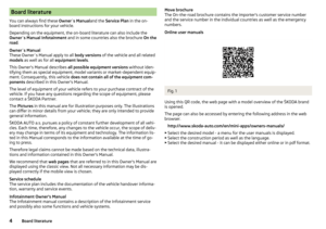 6
6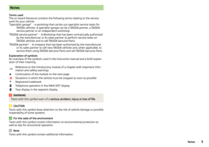 7
7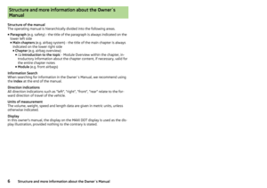 8
8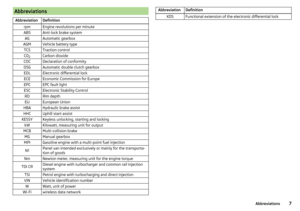 9
9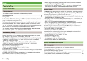 10
10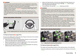 11
11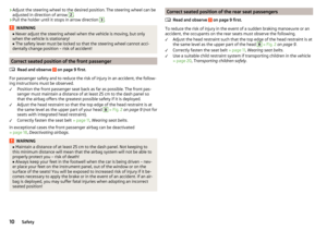 12
12 13
13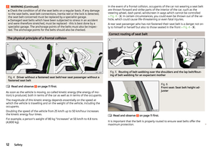 14
14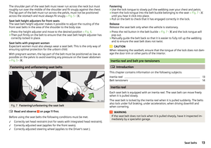 15
15 16
16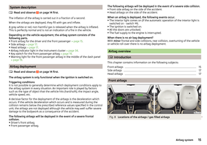 17
17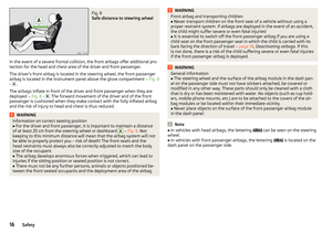 18
18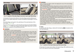 19
19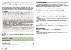 20
20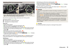 21
21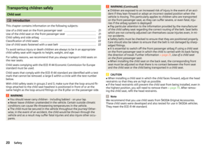 22
22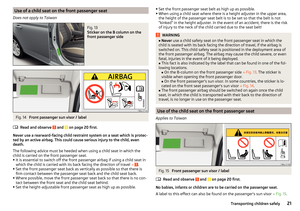 23
23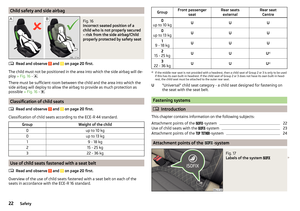 24
24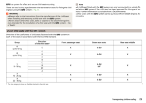 25
25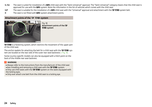 26
26 27
27 28
28 29
29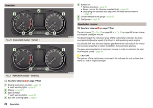 30
30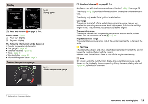 31
31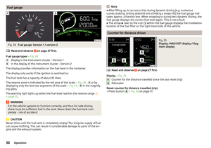 32
32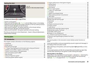 33
33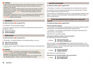 34
34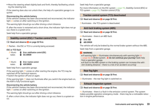 35
35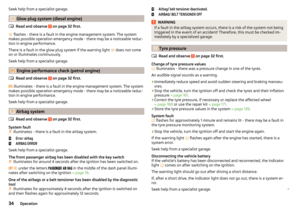 36
36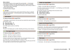 37
37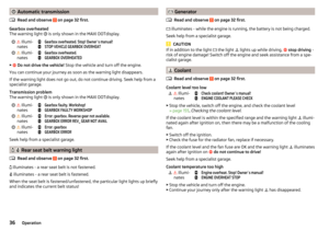 38
38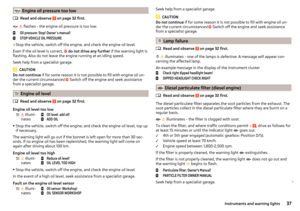 39
39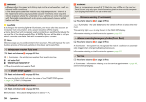 40
40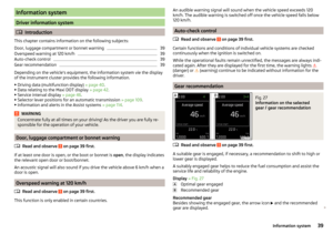 41
41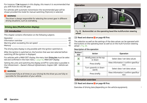 42
42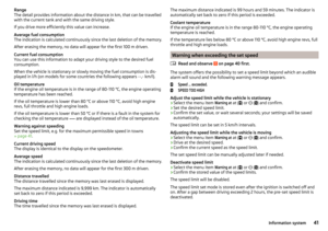 43
43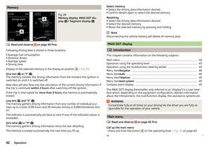 44
44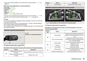 45
45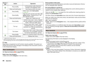 46
46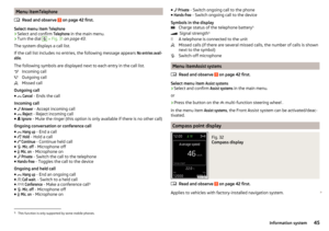 47
47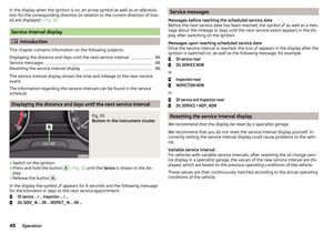 48
48 49
49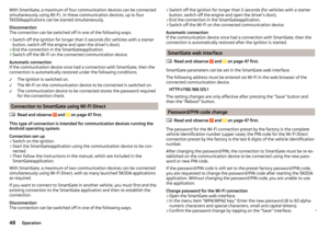 50
50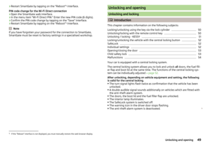 51
51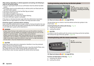 52
52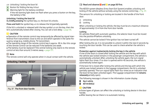 53
53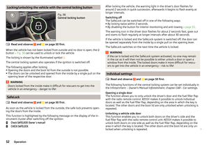 54
54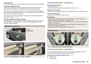 55
55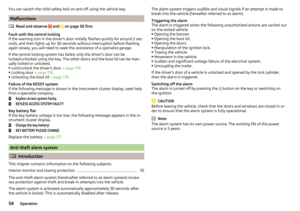 56
56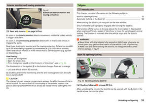 57
57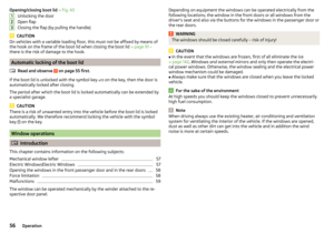 58
58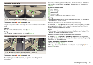 59
59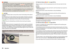 60
60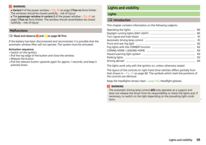 61
61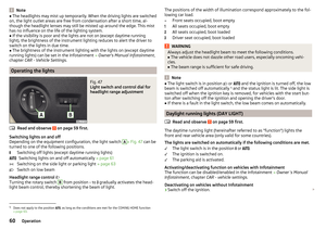 62
62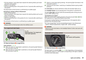 63
63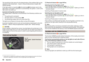 64
64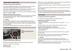 65
65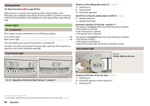 66
66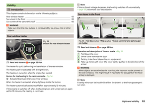 67
67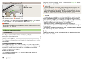 68
68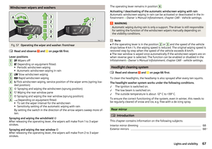 69
69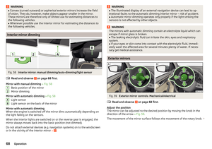 70
70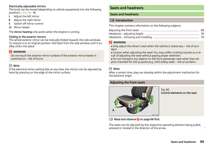 71
71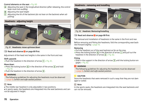 72
72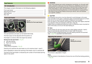 73
73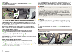 74
74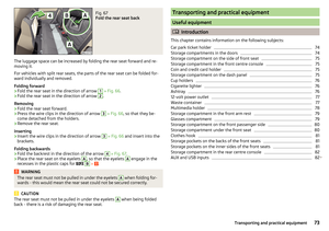 75
75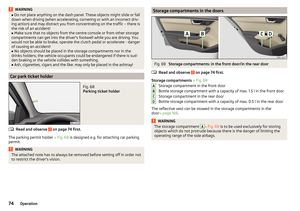 76
76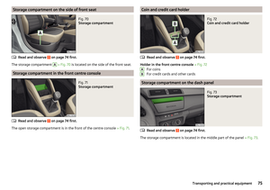 77
77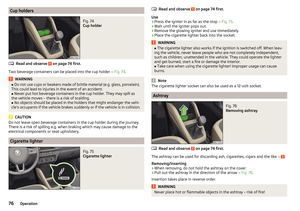 78
78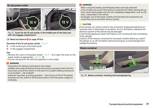 79
79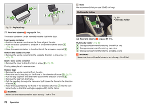 80
80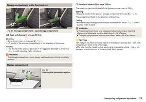 81
81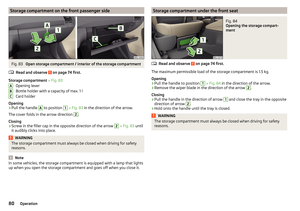 82
82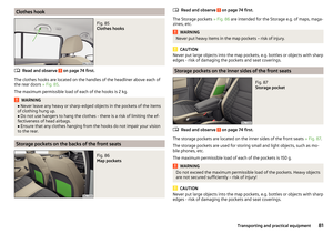 83
83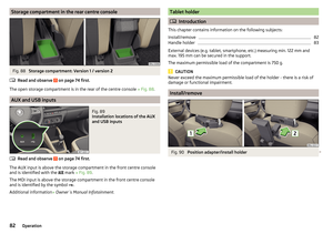 84
84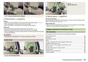 85
85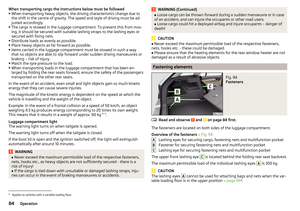 86
86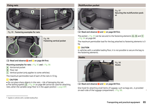 87
87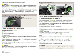 88
88 89
89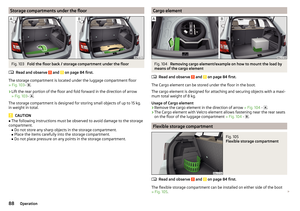 90
90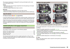 91
91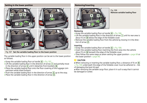 92
92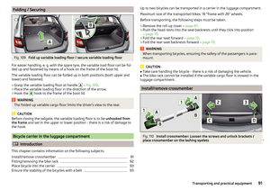 93
93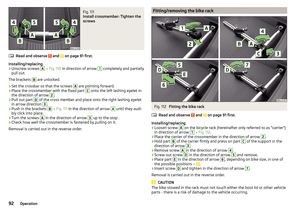 94
94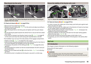 95
95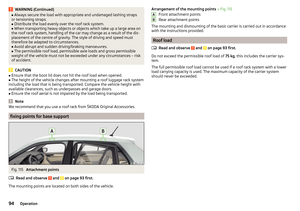 96
96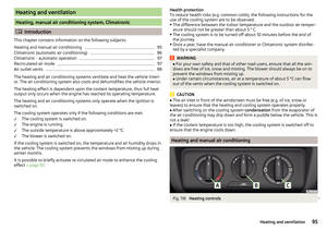 97
97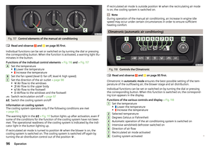 98
98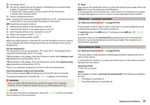 99
99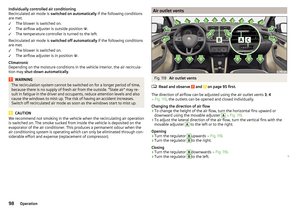 100
100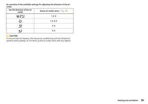 101
101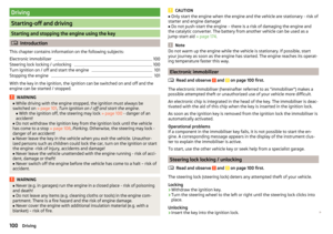 102
102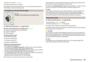 103
103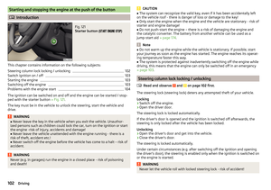 104
104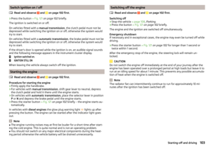 105
105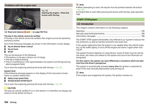 106
106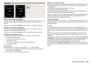 107
107 108
108 109
109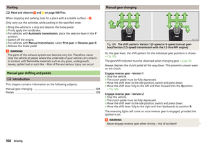 110
110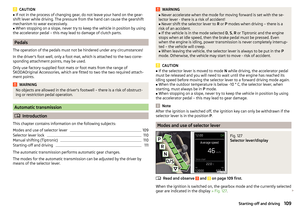 111
111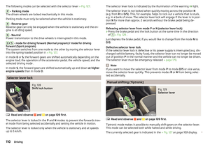 112
112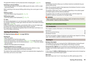 113
113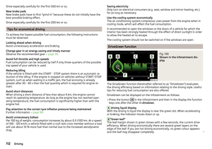 114
114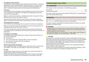 115
115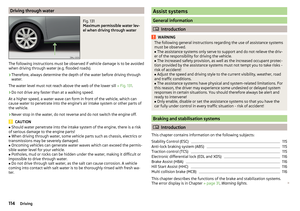 116
116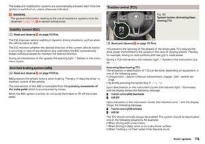 117
117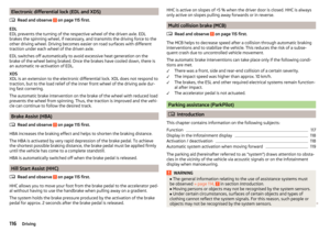 118
118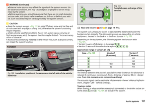 119
119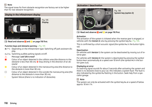 120
120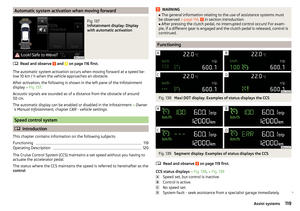 121
121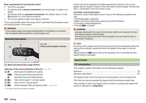 122
122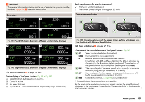 123
123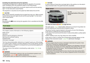 124
124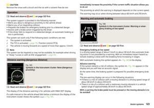 125
125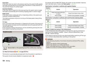 126
126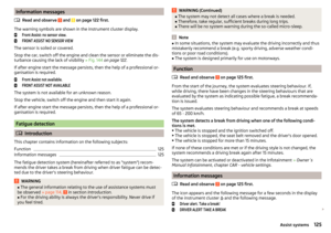 127
127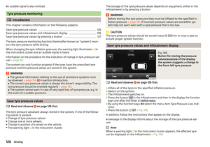 128
128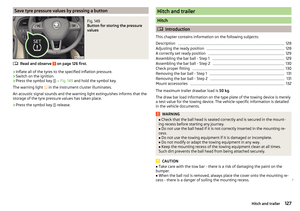 129
129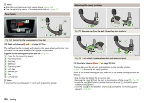 130
130 131
131 132
132 133
133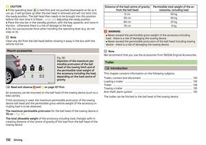 134
134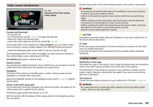 135
135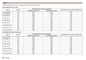 136
136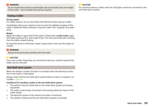 137
137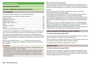 138
138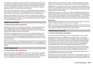 139
139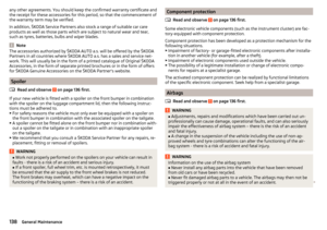 140
140 141
141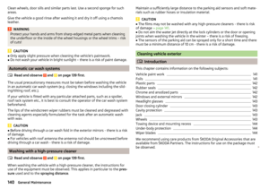 142
142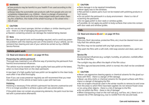 143
143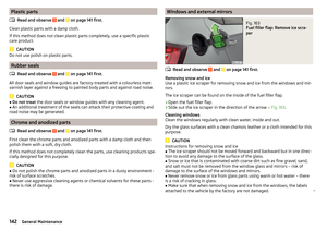 144
144 145
145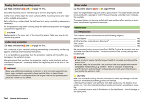 146
146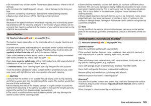 147
147 148
148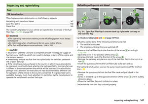 149
149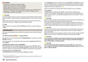 150
150 151
151 152
152 153
153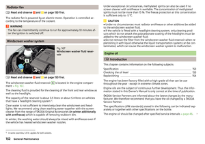 154
154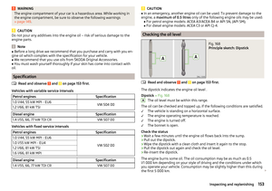 155
155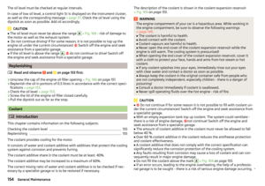 156
156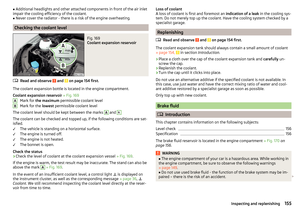 157
157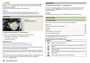 158
158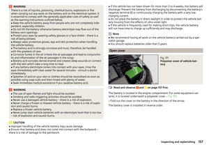 159
159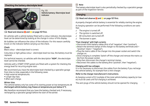 160
160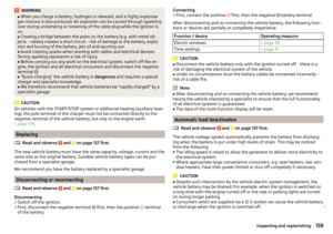 161
161 162
162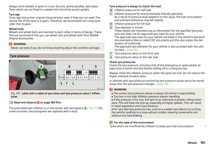 163
163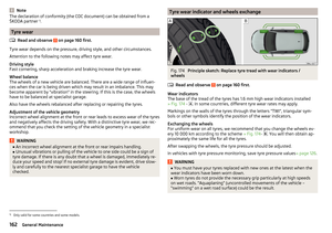 164
164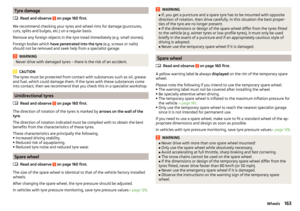 165
165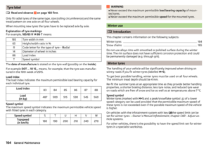 166
166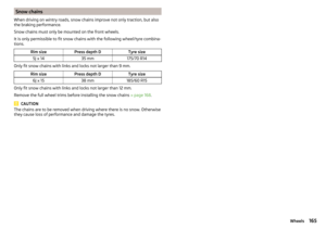 167
167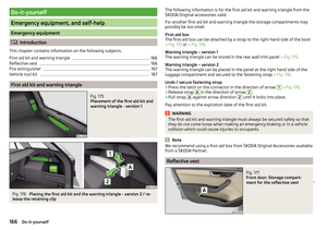 168
168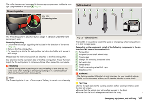 169
169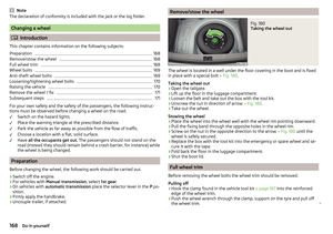 170
170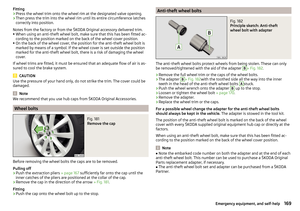 171
171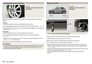 172
172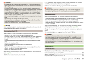 173
173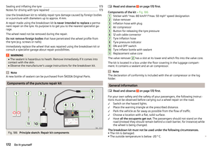 174
174 175
175 176
176 177
177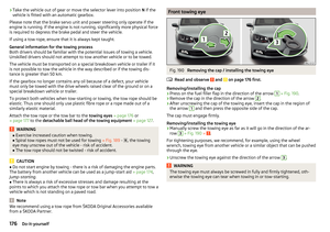 178
178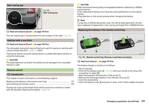 179
179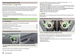 180
180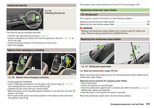 181
181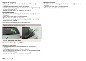 182
182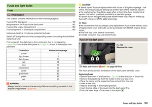 183
183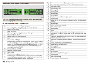 184
184 185
185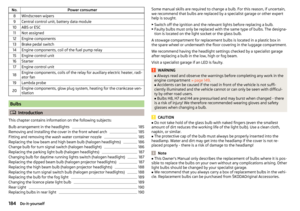 186
186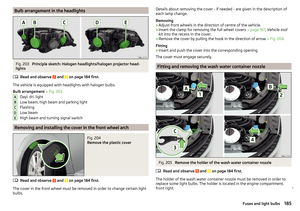 187
187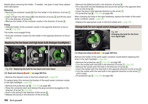 188
188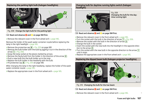 189
189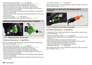 190
190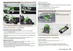 191
191 192
192 193
193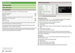 194
194 195
195 196
196 197
197 198
198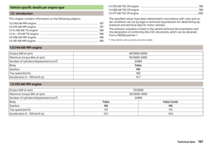 199
199 200
200 201
201 202
202 203
203 204
204 205
205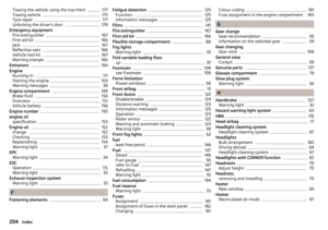 206
206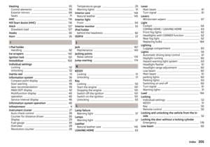 207
207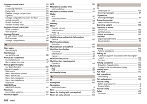 208
208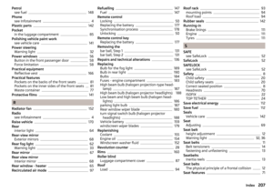 209
209 210
210 211
211 212
212 213
213 214
214 215
215 216
216 217
217 218
218 219
219