Page 89 of 164
 — If Equipped
Personal Settings allows you to set and recall features when the transmission is in PARK.
If the transmission is out")
PROGRAMMABLE FEATURES
Electronic Vehicle Information Center (EVIC) — If Equipped
Personal Settings allows you to set and recall features when the transmission is in PARK.
If the transmission is out of PARK or the vehicle begins moving, a warning message
SYSTEM SETUP NOT AVAILABLE VEHICLE NOT IN PARK displays when you try to select
“System Setup” from the main menu.
The EVIC can be used to program the following Personal Settings. Push the RIGHT arrow
buttonuntil Personal Settings displays, then push the DOWN buttonto scroll
through the settings. Push the RIGHT arrow buttonto change the setting.
•SelectLanguage•Key-OffPowerDelay
•Nav-TurnByTurn•IlluminatedApproach
•AutoLockDoors•HillStartAssist
•AutoUnlockDoors•FlasherswithSlidingDoor
•RemoteUnlockSequence•CalibrateCompass
•RemoteStartComfortSys.•CompassVariance
•HornwithRemoteLock•ParkAssist-IfEquipped
•FlashLampsWithLock•AutomaticHighBeams-IfEquipped
•HeadlampOffDelay•KeylessEnter-N-Go-IfEquipped
•HeadlampsWithWipers•RKELinkedToMemory-IfEquipped
Key Fob Programmable Features
The following features may also be programmed by using the Key Fob transmitter or the
ignition switch and driver's door lock switch.
NOTE:
Pushing the LOCK button while you are inside the vehicle will activate the Vehicle Security
Alarm. Opening a door with the Vehicle Security Alarm activated will cause the alarm to
sound. Push the UNLOCK button to deactivate the Vehicle Security Alarm.
Unlock On First Press
To u n l o c k e i t h e r t h e d r i v e r ' s s i d e , o r a l l d o o r s , o n t h e f i r s t p u s h o f t h e U N L O C K b u t t o n :
•PushandholdtheLOCKbuttonforatleastfourseconds,butnolongerthan10
seconds. Then, push and hold the UNLOCK button while still holding the LOCK button.
•Releasebothbuttonsatthesametime.
ELECTRONICS
87
Page 90 of 164
Auto Unlock Doors On Exit
To h a v e a l l o f t h e v e h i c l e d o o r s u n l o c k w h e n a n y d o o r i s o p e n e d :
•Enteryourvehicleandcloseallthedoors,andfastenyourseatbelt.
•CycletheignitionswitchbetweentheLOCKandONpositionfourtimes,endinginthe
LOCK position (do not start the engine).
•PushthepowerdoorUNLOCKswitchtounlockthedoors.Asinglechimewillindicate
that programming is complete.
Sound Horn With Lock
To t u r n t h e h o r n c h i r p o n o r o f f w h e n t h e d o o r s a r e l o c k e d :
•PushtheLOCKbuttonandPANICbuttonatthesametimeforatleastfourseconds,
but no longer than 10 seconds.
•Releasebothbuttonsatthesametime.
Flashing Lights With Lock
The turn signal lights flash when the doors are locked, which can be turned on or off. To
turn this feature on or off:
•PushandholdtheUNLOCKbuttonandtheLOCKbuttonatthesametimeforatleast
four seconds, but no longer than 10 seconds.
•Releasebothbuttonsatthesametime.
ELECTRONICS
88
Page 91 of 164

HomeLink®replaces up to three hand-held transmitters that operate devices such as
garage door openers, motorized gates, lighting or home security systems. Th")
UNIVERSAL GARAGE DOOR OPENER (HomeLink®)
HomeLink®replaces up to three hand-held transmitters that operate devices such as
garage door openers, motorized gates, lighting or home security systems. The HomeLink®
unit is powered by your vehicles 12 Volt battery.
The HomeLink®buttons that are located in the overhead console or sunvisor designate the
three different HomeLink®channels.
The HomeLink®indicator is located above the center button.
Before You Begin Programming
HomeLink®
Ensure that your vehicle is parked outside
of the garage before you begin program-
ming.
For efficient programming and accurate
transmission of the radio-frequency signal,
it is recommended that a new battery be
placed in the hand-held transmitter of the
device that is being programmed to the
HomeLink®system.
To e r a s e t h e c h a n n e l s , p l a c e t h e i g n i t i o n
switch into the ON/RUN position, then
push and hold the two outside HomeLink®
buttons (I and III) for up to 20 seconds or until the red indicator flashes.
NOTE:
Erasing all channels should only be performed when programming HomeLink®for the first
time. Do not erase channels when programming additional buttons.
If you have any problems, or require assistance, please call toll-free 1-800-355-3515 or,
on the Internet at HomeLink.com for information or assistance.
Programming A Rolling Code
NOTE:
For programming Garage Door Openers that were manufactured after 1995. These Garage
Door Openers can be identified by the “LEARN” or “TRAIN” button located where the
hanging antenna is attached to the Garage Door Opener. It is NOT the button that is
normally used to open and close the door. The name and color of the button may vary by
manufacturer.
1. Place the ignition switch into the ON/RUN position.
2. Place the hand-held transmitter 1 to 3 inches (3 to 8 cm) away from the HomeLink®
button you wish to program while keeping the HomeLink®indicator light in view.
HomeLink® Buttons
ELECTRONICS
89
Page 92 of 164

3. Push and hold the HomeLink®button you want to program while you push and hold
the hand-held transmitter button.
4. Continue to hold both buttons and observe the indicator light. The HomeLink®
indicator will flash slowly and then rapidly after HomeLink®has received the fre-
quency signal from the hand-held transmitter. Release both buttons after the indicator
light changes from slow to rapid.
5. At the garage door opener motor (in the garage), locate the “LEARN” or “TRAINING”
button. This can usually be found where the hanging antenna wire is attached to the
garage door opener motor. Firmly push and release the “LEARN” or “TRAINING”
button.
NOTE:
Yo u h a v e 3 0 s e c o n d s i n w h i c h t o i n i t i a t e t h e n e x t s t e p a f t e r t h e L E A R N b u t t o n h a s b e e n
pushed.
6. Return to the vehicle and push the programmed HomeLink®button twice (holding the
button for two seconds each time). If the device is plugged in and activates,
programming is complete.
NOTE:
If the device does not activate, push the button a third time (for two seconds) to complete
the training.
7. To program the remaining two HomeLink®buttons, repeat each step for each
remaining button. DO NOT erase the channels.
Programming A Non-Rolling Code
NOTE:
For programming Garage Door Openers manufactured before 1995.
1. Turn the ignition switch to the ON/RUN position.
2. Place the hand-held transmitter 1 to 3 inches (3 to 8 cm) away from the HomeLink®
button you wish to program while keeping the HomeLink®indicator light in view.
3. Push and hold the HomeLink®button you want to program while you push and hold
the hand-held transmitter button.
4. Continue to hold both buttons and observe the indicator light. The HomeLink®
indicator will flash slowly and then rapidly after HomeLink®has received the fre-
quency signal from the hand-held transmitter. Release both buttons after the indicator
light changes from slow to rapid.
5. Push and hold the programmed HomeLink®button and observe the indicator light. If
the indicator light stays on constantly, programming is complete and the garage door
(or device) should activate when the HomeLink®button is pushed.
6. To program the two remaining HomeLink®buttons, repeat each step for each
remaining button. DO NOT erase the channels.
ELECTRONICS
90
Page 93 of 164

Using HomeLink®
To o p e r a t e , p u s h a n d r e l e a s e t h e p r o g r a m m e d H o m e L i n k®button. Activation will now
occur for the programmed device (e.g., garage door opener, gate operator, security system,
entry door lock, home/office lighting, etc.,). The hand-held transmitter of the device may
also be used at any time.
WARNING!
•Yourmotorizeddoororgatewillopenandclosewhileyouareprogrammingthe
universal transceiver. Do not program the transceiver if people or pets are in the
path of the door or gate.
•Donotrunyourvehicleinaclosedgarageorconfinedareawhileprogrammingthe
transceiver. Exhaust gas from your vehicle contains Carbon Monoxide (CO) which is
odorless and colorless. Carbon Monoxide is poisonous when inhaled and can cause
you and others to be severely injured or killed.
POWER INVERTER
There is a 115 Volt, 150 Watt power inverter outlet located on the left rear trim panel
immediately behind the second row left passenger seat. This outlet can power cellular
phones, electronics and other low power devices requiring power up to 150 Watts.
•Pushtheswitchlocatedinthecenterof
the instrument panel to turn the power to
the outlet on.
•Pushtheswitchagaintoturnthepower
off.
The status indicator of the AC power in-
verter indicates whether the inverter is pro-
ducing AC power.
NOTE:
The power inverter is designed with built-in
overload protection. If the power rating of
150 Watts is exceeded, the power inverter
will automatically shut down. Once the
electrical device has been removed from
the outlet, the inverter should automatically
reset. If the power rating exceeds approxi-
mately 170 Watts, the power inverter may
have to be reset manually. To reset the
inverter manually, unplug the device and plug it in again. To avoid overloading the circuit,
check the power ratings on electrical devices prior to using the inverter.
Power Inverter
1—PowerOutlet2—PowerInverter
ELECTRONICS
91
Page 94 of 164

WARNING!
To A v o i d S e r i o u s I n j u r y o r D e a t h D O N O T:
•useathree-prongadaptor
•insertanyobjectsintothereceptacles
•touchwithwethands
Close the lid when not in use. If this outlet is mishandled, it may cause an electric
shock and failure.
POWER OUTLETS
•Two12Volt(13Amp)poweroutletsare
located on the lower instrument panel,
below the open storage bin. The driver-
side power outlet is controlled by the
ignition switch and the passenger-side
power outlet is connected directly to the
battery. The driver-side power outlet will
also operate a conventional cigar lighter
unit (if equipped with an optional Smok-
er's Package).
•Oneoutletintheremovablefloorconsole
(if equipped) shares a fuse with the lower
outlet in the instrument panel and is also
connected to the battery. Do not exceed a
maximum power of 160 Watts
(13 Amps) shared between the lower
panel outlet and the removable floor console outlet.
•OnvehiclesequippedwiththeSuperConsolethepoweroutletsarelocatedunderthe
retractable cover. To access the power outlets push down on the cover and slide it
toward the instrument panel.
•Theoutletintherearquarterpanelneartheliftgateandtheupperoutletinthe
instrument panel are both controlled by the ignition switch. Each of these outlets can
support 160 Watts (13 Amps). Do not exceed 160 Watts (13 Amps) for each of these
outlets.
Power Outlets
ELECTRONICS
92
Page 95 of 164
NOTE:
•Donotexceedthemaximumpowerof160Watts(13Amps)at12Volts.Ifthe160
Watt (13 Amp) power rating is exceeded, the fuse protecting the system will need to be
replaced.
•Poweroutletsaredesignedforaccessoryplugsonly.Donotinsertanyotherobjectin
the power outlet as this will damage the outlet and blow the fuse. Improper use of the
power outlet can cause damage not covered by your new vehicle warranty.
Fuse Panel
1—M7Fuse20AmpYellow—PowerOutletLeftofSecondRowPassengerSeat2—M6Fuse20AmpYellow—CigarLighter/PowerOutletInstrumentPanel3—M36Fuse20AmpYellow—PowerOutletInstrumentPanel&InConsole—IfEquipped
ELECTRONICS
93
Page 96 of 164

IN-FLOOR STORAGE — STOW'N GO®
Second Row Seat Storage Bins
Storage bins are located in the floor in front of the second row seats that can be used when
the second row seat is in the upright position. Pull up on the storage bin latch to open the
cover. Slide the storage bin locking mechanism to the "Lock" position to allow greater
access to the storage bin.
Cargo Area Storage
The liftgate sill plate has a raised line with the statement “Load To This Line”. This line
indicates how far rearward cargo can be placed without interfering with liftgate closing.
WARNING!
In a collision, serious injury could result if the seat storage bin covers are not properly
latched. Do not drive the vehicle with the storage bin covers open. Keep the storage bin
covers closed and latched while the vehicle is in motion. Do not use a storage bin latch
as a tie down.
ROOF LUGGAGE RACK
The crossbars on your vehicle are delivered stowed within the roof rack side rails. When
installed, the roof rack can hold a maximum of 150 lbs (68 kg) of evenly distributed
weight.
Installing The Crossbars
1. To install the crossbars, completely
loosen the thumb screws at both ends
and lift the crossbar from its stowed
position.
2. Bend the pivot points at each end of the
crossbar and slide the thumb screw
down.
3. Set the crossbars into position and
tighten the thumb screws.
NOTE:
Make sure the directional arrow on the
crossbar aligns with the directional arrow on
the side rail.
Refer to the Owner's Manual on the DVD for
further details.
Crossbar
1—DirectionalArrow2—PivotPoint3—ThumbScrew
UTILITY
94
 1
1 2
2 3
3 4
4 5
5 6
6 7
7 8
8 9
9 10
10 11
11 12
12 13
13 14
14 15
15 16
16 17
17 18
18 19
19 20
20 21
21 22
22 23
23 24
24 25
25 26
26 27
27 28
28 29
29 30
30 31
31 32
32 33
33 34
34 35
35 36
36 37
37 38
38 39
39 40
40 41
41 42
42 43
43 44
44 45
45 46
46 47
47 48
48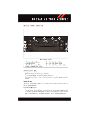 49
49 50
50 51
51 52
52 53
53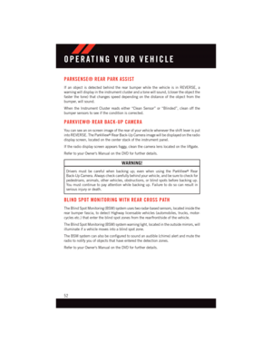 54
54 55
55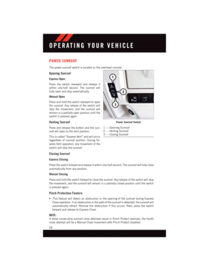 56
56 57
57 58
58 59
59 60
60 61
61 62
62 63
63 64
64 65
65 66
66 67
67 68
68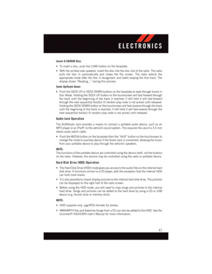 69
69 70
70 71
71 72
72 73
73 74
74 75
75 76
76 77
77 78
78 79
79 80
80 81
81 82
82 83
83 84
84 85
85 86
86 87
87 88
88 89
89 90
90 91
91 92
92 93
93 94
94 95
95 96
96 97
97 98
98 99
99 100
100 101
101 102
102 103
103 104
104 105
105 106
106 107
107 108
108 109
109 110
110 111
111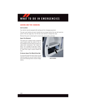 112
112 113
113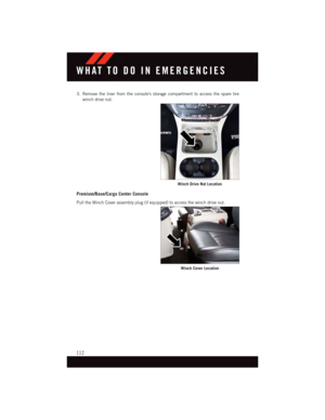 114
114 115
115 116
116 117
117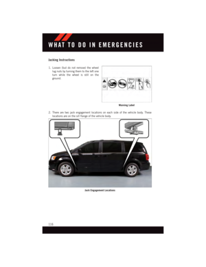 118
118 119
119 120
120 121
121 122
122 123
123 124
124 125
125 126
126 127
127 128
128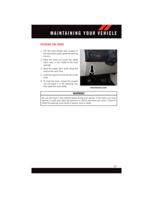 129
129 130
130 131
131 132
132 133
133 134
134 135
135 136
136 137
137 138
138 139
139 140
140 141
141 142
142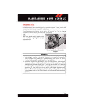 143
143 144
144 145
145 146
146 147
147 148
148 149
149 150
150 151
151 152
152 153
153 154
154 155
155 156
156 157
157 158
158 159
159 160
160 161
161 162
162 163
163
at12Volts.Ifthe160
Watt (13 Amp) power rating is exceeded, the fuse protecting the system will need to be
replaced.
•Poweroutletsaredesignedforac")