Page 137 of 164
** The spark plug change interval is mileage based only, yearly intervals do not apply.
WARNING!
•Youcanbebadlyinjuredworkingonoraroundamotorvehicle.Doonlyserviceworkforwhichyouhavetheknowledgeandtheright
equipment. If you have any doubt about your ability to perform a service job, take your vehicle to a competent mechanic.
•Failuretoproperlyinspectandmaintainyourvehiclecouldresultinacomponentmalfunctionandeffectvehiclehandlingand
performance. This could cause an accident.
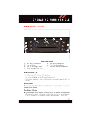
MAINTAINING YOUR VEHICLE
135
Page 138 of 164
MAINTENANCE RECORD
Odometer Date Signature, Autho-
rized Service Center
20,000 Miles(32,000 km) or2Years30,000 Miles(48,000 km) or3Years40,000 Miles(64,000 km) or4Years50,000 Miles(80,000 km) or5Years60,000 Miles(96,000 km) or6Years70,000 Miles(112,000 km) or7Years80,000 Miles(128,000 km) or8Years
Odometer Date Signature, Autho-
rized Service Center
90,000 Miles(144,000 km) or9Years100,000 Miles(160,000 km) or10 Years110,000 Miles(176,000 km) or11 Years120,000 Miles(192,000 km) or12 Years130,000 Miles(208,000 km) or13 Years140,000 Miles(224,000 km) or14 Years150,000 Miles(240,000 km) or15 Years
MAINTAINING YOUR VEHICLE
136
Page 139 of 164
FUSES
MAINTAINING YOUR VEHICLE
137
Page 140 of 164

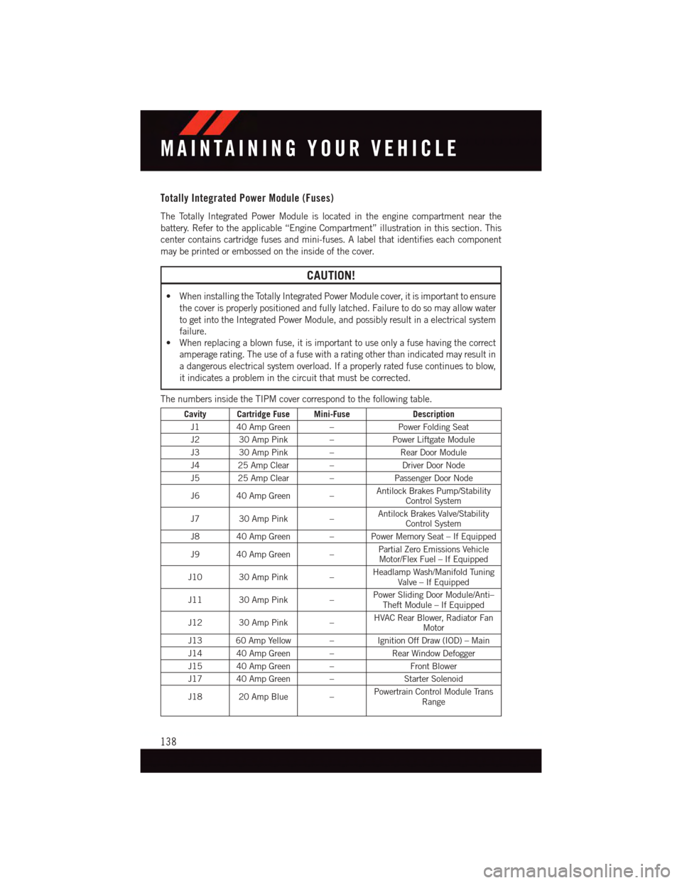
Totally Integrated Power Module (Fuses)
The Totally Integrated Power Module is located in the engine compartment near the
battery. Refer to the applicable “Engine Compartment” illustration in this section. This
center contains cartridge fuses and mini-fuses. A label that identifies each component
may be printed or embossed on the inside of the cover.
CAUTION!
•WheninstallingtheTotallyIntegratedPowerModulecover,itisimportanttoensure
the cover is properly positioned and fully latched. Failure to do so may allow water
to get into the Integrated Power Module, and possibly result in a electrical system
failure.
•Whenreplacingablownfuse,itisimportanttouseonlyafusehavingthecorrect
amperage rating. The use of a fuse with a rating other than indicated may result in
adangerouselectricalsystemoverload.Ifaproperlyratedfusecontinuestoblow,
it indicates a problem in the circuit that must be corrected.
The numbers inside the TIPM cover correspond to the following table.
Cavity Cartridge Fuse Mini-FuseDescription
J1 40 Amp Green –Power Folding Seat
J2 30 Amp Pink –Power Liftgate Module
J3 30 Amp Pink –Rear Door Module
J4 25 Amp Clear –Driver Door Node
J5 25 Amp Clear –Passenger Door Node
J6 40 Amp Green –Antilock Brakes Pump/StabilityControl System
J7 30 Amp Pink –Antilock Brakes Valve/StabilityControl System
J8 40 Amp Green – Power Memory Seat – If Equipped
J9 40 Amp Green –Partial Zero Emissions VehicleMotor/Flex Fuel – If Equipped
J10 30 Amp Pink –Headlamp Wash/Manifold TuningValve – If Equipped
J11 30 Amp Pink –Power Sliding Door Module/Anti–Theft Module – If Equipped
J12 30 Amp Pink –HVAC Rear Blower, Radiator FanMotor
J13 60 Amp Yellow – Ignition Off Draw (IOD) – Main
J14 40 Amp Green –Rear Window Defogger
J15 40 Amp Green –Front Blower
J17 40 Amp Green –Starter Solenoid
J18 20 Amp Blue –Powertrain Control Module TransRange
MAINTAINING YOUR VEHICLE
138
Page 141 of 164

Cavity Cartridge Fuse Mini-FuseDescription
J19 60 Amp Yellow –Radiator Fan
J20 30 Amp Pink –Front Wiper LO/HI
J21 20 Amp Blue –Front/Rear Washer
J22 25 Amp Clear –Sunroof Module
M1–15AmpBlueRear Center Brake Lamp/BrakeSwitch
M2–20AmpYellow FrontFogLamps
M3–20AmpYellowFront/Rear Axle Locker, VacuumPump Motor
M4–10AmpRedTr a i l e r To w
M5–25AmpClearInverter
M6–20AmpYellowPower Outlet #1 (ACC), Rain Sen-sor, Cigar Lighter (InstrumentPanel or with Console Rear)
M7–20AmpYellowPower Outlet #2 (BATT/ACC SE-LECT) – Center Seat or with Con-sole Rear
M8–20AmpYellowFrontHeatedSeat–IfEquipped
M9–20AmpYellowRearHeatedSeat–IfEquipped
M10–15AmpBlue
Ignition Off Draw — Video Sys-tem, Satellite Radio, DVD, Hands-Free Module, Universal GarageDoor Opener, Vanity Lamp,Streaming Video Module – IfEquipped
M11–10AmpRedClimateControlSystem
M12–30AmpGreenAmplifier/Radio
M13–20AmpYellowInstrument Cluster, SIREN, ClockModule, Multi-Function ControlSwitch – If Equipped
M14–20AmpYellowTrailerTow–IfEquipped
M15–20AmpYellow
Rear View Mirror, Instrument Clus-ter, Multi-Function Control Switch,Ti r e P r e s s u r e M o n i t o r, G l o w P l u gModule – If Equipped
M16–10AmpRedAirbag Module/Occupant Classifi-cation Module
M17–15AmpBlueLeft Tail/License/Park Lamp, Run-ning Lamps
M18–15AmpBlueRightTail/Park/RunLamp
M19–25AmpClearPowertrain
M20–15AmpBlueInstrument Cluster Interior Light,Switch Bank, Steering ColumnModule, Switch Steering Wheel
MAINTAINING YOUR VEHICLE
139
Page 142 of 164

Cavity Cartridge Fuse Mini-FuseDescription
M21–20AmpYellowPowertrain
M22–10AmpRedHorn
M23–10AmpRedHorn
M24–25AmpClearRear Wiper
M25–20AmpYellowFuel Pump, Diesel Lift Pump – IfEquipped
M26–10AmpRedPower Mirror Switch, Driver Win-dow Switch
M27–10AmpRedWireless Control Module, KeylessEntry Module
M28–10AmpRedPowertrain, Transmission ControlModule
M29–10AmpRedOccupantClassificationModule
M30–15AmpBlueRear Wiper Module, Power FoldingMirror
M31–20AmpYellow Back-UpLamps
M32–10AmpRedAirbag Module, THATCHUM – IfEquipped
M33–10AmpRedPowertrain
M34–10AmpRed
Park Assist, Heater Climate Con-trol Module, Headlamp Wash,Compass, Rear Camera, DoorLamps, Flashlight, Relay DieselCabin Heater, Rad Fan Diesel – IfEquipped
M35–10AmpRedHeated Mirrors
M36–20AmpYellowPower Outlet #3 (InstrumentPanel or with Console Center)
M37–10AmpRedAntilock Brakes, Stability Control,Stop Lamp, Fuel Pump
M38–25AmpClearDoor Lock/Unlock Motors, LiftgateLock/Unlock Motors
The power windows are fused by a 25 Amp circuit breaker located in the Totally Integrated
Power Module.
MAINTAINING YOUR VEHICLE
140
Page 143 of 164

TIRE PRESSURES
Check the inflation pressure of each tire, including the spare tire, at least monthly and
inflate to the recommended pressure for your vehicle.
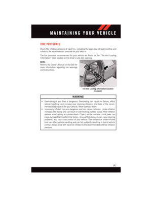
The tire pressures recommended for your vehicle are found on the “Tire and Loading
Information” label located on the driver’s side door opening.
NOTE:
Refer to the Owner's Manual on the DVD for
more information regarding tire warnings
and instructions.
WARNING!
•Overloadingofyourtiresisdangerous.Overloadingcancausetirefailure,affect
vehicle handling, and increase your stopping distance. Use tires of the recom-
mended load capacity for your vehicle. Never overload them.
•Improperlyinflatedtiresaredangerousandcancausecollisions.Under-inflation
increases tire flexing and can result in over-heating and tire failure. Over-inflation
reduces a tire’s ability to cushion shock. Objects on the road and chuck holes can
cause damage that results in tire failure. Unequal tire pressures can cause steering
problems. You could lose control of your vehicle. Over-inflated or under-inflated
tires can affect vehicle handling and can fail suddenly, resulting in loss of vehicle
control. Always drive with each tire inflated to the recommended cold tire inflation
pressure.
Tire And Loading Information Location(Example)
MAINTAINING YOUR VEHICLE
141
Page 144 of 164

SPARE TIRES — IF EQUIPPED
NOTE:
For vehicles equipped with Tire Service Kit instead of a spare tire, please refer to “Tire
Service Kit” in “What To Do In Emergencies” on your DVD for further information.
CAUTION!
Because of the reduced ground clearance, do not take your vehicle through an
automatic car wash with a compact or limited-use temporary spare installed. Damage
to the vehicle may result.
Spare Tire Matching Original Equipped Tire And Wheel — If Equipped
Yo u r v e h i c l e m a y b e e q u i p p e d w i t h a s p a r e t i r e a n d w h e e l e q u i v a l e n t i n l o o k a n d f u n c t i o n
to the original equipment tire and wheel found on the front or rear axle of your vehicle. This
spare tire may be used in the tire rotation for your vehicle. If your vehicle has this option,
refer to an authorized tire dealer for the recommended tire rotation pattern.
Compact Spare Tire — If Equipped
The compact spare is for temporary emergency use only. You can identify if your vehicle
is equipped with a compact spare by looking at the spare tire description on the Tire and
Loading Information Placard located on the driver’s side door opening or on the sidewall
of the tire. Compact spare tire descriptions begin with the letter “T” or “S” preceding the
size designation. Example: T145/80D18 103M.
T, S = Temporary Spare Tire
Since this tire has limited tread life, the original equipment tire should be repaired (or
replaced) and reinstalled on your vehicle at the first opportunity.
Do not install a wheel cover or attempt to mount a conventional tire on the compact spare
wheel, since the wheel is designed specifically for the compact spare tire. Do not install
more than one compact spare tire and wheel on the vehicle at any given time.
WARNING!
Compact spares are for temporary emergency use only. With these spares, do not drive
more than 50 mph (80 km/h). Temporary use spares have limited tread life. When the
tread is worn to the tread wear indicators, the temporary use spare tire needs to be
replaced. Be sure to follow the warnings, which apply to your spare. Failure to do so
could result in spare tire failure and loss of vehicle control.
MAINTAINING YOUR VEHICLE
142